A different sort of box

If you will let me know what stock thickness you would like to use, and what box dimensions you want, and whether you want a hinged or sliding lid, I’ll gladly work up a step-by-step tutorial for that size.

1 Like

That would be cool. We’re currently in the middle of a move, and my shop is out of commission while I build up the new space, but I’d love to take you up on it. My real question is if all the work done in OpenSCAD is necessary or if you could fully do this in CC or Fusion?

Unfortunately, it’s not workable to do all the design for CAM in OpenSCAD — it won’t write out G-Code, and it can’t do an open geometry — still looking for a CAD/CAM tool which suits me which can do these things.

I show doing this in Carbide Create alone at:

Yes, it could be done in Fusion — I think one of the links at:

shows that.

Looking at the finished box, I got to thinking about the voids which are left in the sliding version — while thinking on how to address them, I realized that it would be possible to have a minimal hinged (pinned) lid, so the previous hinged option was renamed to “Sawn” and I worked up a Hinged option:

https://www.blockscad3d.com/community/projects/1368564

It will require rounding off the back underside of the lid, but that’s easily done w/ a hand plane or via 3D modeling if one doesn’t have a suitable endmill for doing so. Also one will need to make a fixture to hold things in place while one drills for the hinges.

1 Like

The following OpenSCAD script could be adapted to assist in creating such a 3D model suitable for this box’s lid, if that’s useful:

$fn=100;

module roundOver(radius=5,length=100) {
    translate([0,0,0]) 
    rotate([90,0,90])
    linear_extrude(length)
    difference() {
        square([radius,radius]);
        circle(r=radius);
    }
}

module lid(width=120,depth=60,height=5, fingerRecessWidth=15) {
    difference() {
        cube([width,depth,height]) ;
        translate([width/2,0,fingerRecessWidth/2+height/2]) sphere(r=fingerRecessWidth/2);
        translate([-0.1,depth-height+0.1,0.1]) roundOver(radius=height, length=width+0.2);
    }    
}

lid();

It should make something like this which can be exported to an STL:

I did do something similar, it’s just that I rotate the design so that it couldn’t be seen easily:

The issue is I need to get this into the DXF/SVG, and unfortunately, OpenSCAD doesn’t support 3D DXFs, and I don’t want to create a requirement that folks export an STL and use MeshCAM.

I’ll probably model a cove radius tool and assign a toolpath for that as was done here:

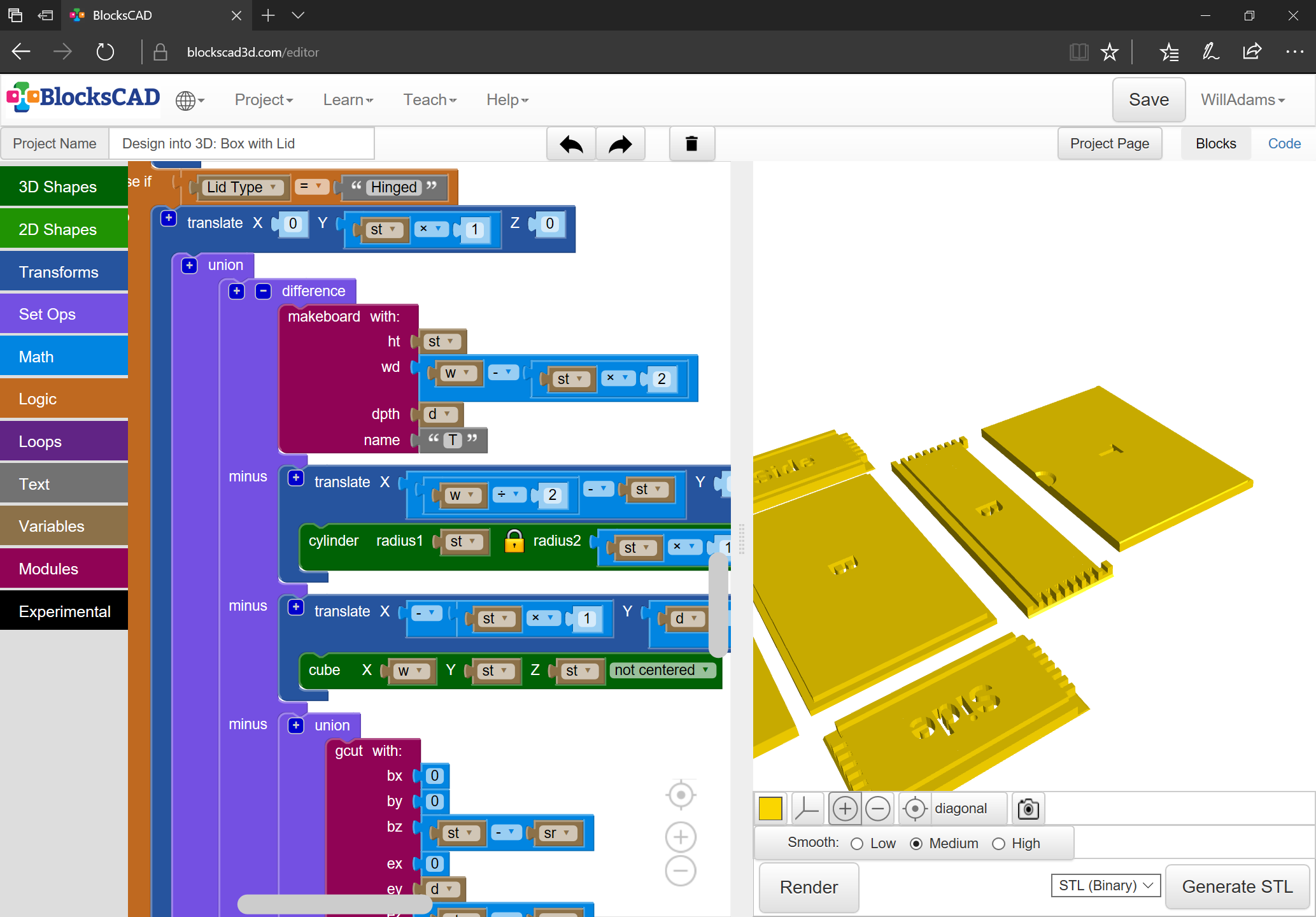
(unfortunately, that doesn’t work in BlockSCAD for some reason — need to revisit that, and if I still can’t get it to work, file a bug report)

then if folks don’t have one of the correct radius it will be on them to model a workaround, say using the technique described at:

Ah, I see.

I thought I saw that, but I can’t access your model properly on BlocksCAD.

The sign-up/login for BlocksCAD doesn’t seem to work for me either.

The link you have shows a page with a few errors:

What sort of SVG would you be looking to generate from this model?

I want to get an SVG which can then be imported into Carbide Create to cut things out — see the posts above:

I had thought it was possible to edit a copy of a project in BlockSCAD — do you not get a “Create my Own” button which loads a copy?

Will have to look into that. There’s an OpenSCAD in the cloud effort which is getting started — I’m advocating for adding support for projection() and the Customizer which would make it really good for this — the only things then lacking would be the ability to do open/unclosed geometry and the ability to write out G-Code.

I have a “Create My Own” button showing, but it just loads an empty project… which is fine - BlocksCAD is not my cup’o’tea.

In the narrative above, you mix OpenSCAD and BlocksCAD in a way I don’t really follow, so I’m not sure where you leave one and go into the other.

Once in OpenSCAD you can do a projection to get the outline as an SVG (as you probably know).

1 Like

BlockSCAD has a command for exporting as OpenSCAD — once a project is done I do that, then add the code for projection() and move the variable definitions around and adjust them so that they work for the Customizer feature.

I’ve been exporting an SVG — the problem is it’s a 2D format, and OpenSCAD will only export closed regions, and there isn’t an obvious way to get toolpaths — see above where I show taking the outline of a V carving region and using it to draw a line which can then be used to do the miter instead of using a traditional V carving toolpath.

I’m stuck here because there doesn’t seem to be a 3D modeling tool which:

  • is programmatic
  • has a nice graphical interface (blocks or nodes or something better)
  • can write out text files w/ full user control

which has a license I’m willing to work w/ — this hybrid of BlockSCAD → OpenSCAD → DXF/SVG is the most workable thing I’ve yet found, but it doesn’t do open/unclosed geometry and there isn’t sufficient control over the echo command when writing out to the log file for one to get G-Code which doesn’t require post-processing (which is something which I don’t want to impose on the folks who use my designs).

1 Like

Understood.

I think we’ve discussed this before, but a fork of OpenSCAD could be bent to make some of these things happen … but then there’s maintenance and distribution of the binaries to consider. And it doesn’t have a UI with blocks and nodes (something I don’t like personally but I can see how it might appeal).

I did notice one approach recently with respects to the post processing and ECHO that reduces the skills required to grab the GCode from the OpenSCAD console to one of accurate mouse selection.

$fn=36;
mm_minute=5000;
points=[for(i=[0:$fn])let(iw=360/$fn*(i%$fn))[sin(iw),cos(iw)]];

gcode=function(i=len(points)-1)i==0?"\nG91; relative positioning\n":
str(gcode(i-1),"G1 X",points[i].x," Y",points[i].y," F",mm_minute,"\n");

echo (str("G-code:\n",gcode()));// here the code is displayed within console window
polygon (points);// not needed for the code - just to view

(edit: the basic idea here is to fill an array then render the array as GCode in one hit)

(edit2: I recently looked at the export code for OpenSCAD (they added a few more export formats) and thought it would be possible to write a “slicer” exporter that generated SVGs for horizontal layers of the model, perhaps only writing them when they differed. That would be pretty useful)

(edit3: something that did something like this: SliceCrafter )

I’m currently writing out separate layers as noted above, and have been programming the various parts modules so that they have parameters for tool and depth.

The array idea is interesting — I’ll have to look into it — found it at:

EDIT: looking into it, I don’t see how it could generate code which would work w/ Carbide Motion/Grbl — if I understand it correctly, every line will be preceded by:

G-code:

Not entirely…

The output looks like this:


Parsing design (AST generation)...
Saved backup file: C:/Users/Gerrard/Documents/OpenSCAD/backups/unsaved-backup-xokbbbTG.scad
Compiling design (CSG Tree generation)...
ECHO: "G-code:

G91; relative positioning
G1 X0.173648 Y0.984808 F5000
G1 X0.34202 Y0.939693 F5000
G1 X0.5 Y0.866025 F5000
G1 X0.642788 Y0.766044 F5000
G1 X0.766044 Y0.642788 F5000
G1 X0.866025 Y0.5 F5000
G1 X0.939693 Y0.34202 F5000
G1 X0.984808 Y0.173648 F5000
G1 X1 Y0 F5000
G1 X0.984808 Y-0.173648 F5000
G1 X0.939693 Y-0.34202 F5000
G1 X0.866025 Y-0.5 F5000
G1 X0.766044 Y-0.642788 F5000
G1 X0.642788 Y-0.766044 F5000
G1 X0.5 Y-0.866025 F5000
G1 X0.34202 Y-0.939693 F5000
G1 X0.173648 Y-0.984808 F5000
G1 X0 Y-1 F5000
G1 X-0.173648 Y-0.984808 F5000
G1 X-0.34202 Y-0.939693 F5000
G1 X-0.5 Y-0.866025 F5000
G1 X-0.642788 Y-0.766044 F5000
G1 X-0.766044 Y-0.642788 F5000
G1 X-0.866025 Y-0.5 F5000
G1 X-0.939693 Y-0.34202 F5000
G1 X-0.984808 Y-0.173648 F5000
G1 X-1 Y0 F5000
G1 X-0.984808 Y0.173648 F5000
G1 X-0.939693 Y0.34202 F5000
G1 X-0.866025 Y0.5 F5000
G1 X-0.766044 Y0.642788 F5000
G1 X-0.642788 Y0.766044 F5000
G1 X-0.5 Y0.866025 F5000
G1 X-0.34202 Y0.939693 F5000
G1 X-0.173648 Y0.984808 F5000
G1 X0 Y1 F5000
"
Compiling design (CSG Products generation)...
Geometries in cache: 1
Geometry cache size in bytes: 656
CGAL Polyhedrons in cache: 0
CGAL cache size in bytes: 0
Compiling design (CSG Products normalization)...
Normalized tree has 1 elements!
Compile and preview finished.
Total rendering time: 0:00:00.040
1 Like

Ah, that’s more workable — will definitely experiment w/ that this evening.

1 Like

Worked up an updated BlockSCAD file for this:

https://www.blockscad3d.com/community/projects/1380449

Updated OpenSCAD file available at:

Hi Will!

Again, thanks for your work on this. I used your OpenSCAD file to create a box to hold Chess pieces for my daughter’s boyfriend. This one is 4 x 5.25 x 14.5 inches using 0.25 thick popular. I used the SVG output to import into Carbide Create to create the tool paths. Everything worked out well, but the sliding top was slightly sized incorrectly. It was 1/8 short on both sides and 1/8 too long in the opening direction. Easy fixes, but I am not sure why that happened.

I also added an internal divider to keep all of the pieces from banging into each other.

Still needs to be finished and have some felt glued into it, but it’s looking pretty good.

Side and Front

Side and Rear

Top and Bottom

Divider (Old piece of particle board from the back of a bookcase)

3 Likes

Which file did you use? What settings? Did you save them as a pre-set? If so, send the .scad and .json file to me in a PM (or post here)

Let me know and I’ll do my best to puzzle out where things were off.

Note that on the most recent version I’ve begun explicitly modeling all the pieces, where before was trying to only do the ones which were strictly needed.

I started with the last scad file you posted (Design into 3D_Box with Lid.scad) I’ve attached my file with only the new dimensions entered and the SVG output. The lid seems slightly wrong to me…

Design into 3D_Box with Lid_SBL.zip (24.2 KB)