Adding Feed Hold Switch with 12V Light - Voltage Step-up

Hi @KevinCarr1996,

The FH signal is not really meant to plug anything that draws current on the 5v pin. It’s only a pull-up to 5v that is meant to be pulled to gnd to activate the signal, typically by a passive push button. I’m guessing that stepup adapter draws too much current. If I were you I would just use a simple switch with no light. Not as fancy, but safer for the controller board.

3 Likes

Thank you for the quick response, Julien.
I figured it was something along those lines, but wanted to hear from others to be sure.

No fun in that, though! Get a 12v wall wart and use it for your current switch, future switches, and your future strip lighting.

2 Likes

@neilferreri I was actually just thinking that. I could still have the light; I just have to use a separate power source. Not sure exactly how that wiring would correlate on the switch, though. I’m not the best with wiring.

The 12v is just for the led… Completely separate circuit from the CNC.

I get that, but I only wanted the LED to turn on when the button is pressed, so it would have to be connected to the NO pin as well.

Ahhh, I didn’t realize you got a latching switch. You only need a momentary switch. You want to have it so you must release the switch before pressing cycle start?

Yes, I got it so I can press the switch, with it staying in the closed position (Feed hold on), then when I press it again to release the switch to the open position, the machine will keep running (feed hold off). I wanted the light to only be on during the “feed hold on”, or closed circuit position.

Feed hold doesn’t work quite like that. With your switch, you’d have to press for feed hold, press again to release the feedhold, then issue a cycle start from your computer (assuming a stock C3D controller).

2 Likes

Alright, I’m not sure if I’m reading wrong or what. Just to be clear, Are you saying I’d have to “press” the button 4 times to have it work (2 times to feed hold, 2 times to turn feed hold off). I am running CNCjs; I assumed this connector on the board was a “hard” feed hold, which mean I wouldn’t have to separately press “resume” on my sender software (CNCjs).

I hadn’t tested the switch out yet since I was trying to get the light working first.

UPDATE: I just tested it out with CNCjs. Not at all what I was expecting/looking for. Will have to seek another route to find what I want…

The C3D board has a feedhold input. Cycle start is separate. No dedicated input for the cycle start.
You’ll have to press for feed hold, press to release feed hold, click cycle start on computer.

@neilferreri I am rummaging through old posts from you and Julien. Still reading, but what I have gotten so far is there is no way (Other than editing the GRBL code) to make the FEED_HOLD work how I was looking for? (Press on once to stop, press again to resume - Without any dumb z-axis retract… Just simply stop the feed and resume feed)

I have used industrial CNC machines, where they allow you to use the “feed hold/cycle start” to essentially stop/start the machine feed in quick succession if one wanted to.

Any idea if there’s an alternative way of getting the result I’m looking for? Maybe through CNCjs?

Use the feed hold and cycle start buttons? :wink:
image

Hahahah, yes… I did mean a physical switch, though. I would like to eliminate having to un-concentrate from my work to make sure I click on the right spot on the screen.

Came across this, but unless there’s no other way, I wouldn’t prefer to do this for a resume command

There’s no noise filter doing it that way. If I had one of those new boards with the A3 pin there, I’d recompile grbl with a modified CPU_MAP and add an RC filter to the A3 pin. I’m not a fan of soldering to the microcontroller like that.
It’s definitely a feature I hope they add.
You may have seen my posts about using the abort pin (older board). I used it for years before I noticed a flaw.

So… Update. I ended up finding a way to get what I was looking for!

I used @Julien 's code from his CNCjs handwheel pendant (detailed howto for nerds) post, with modifying the code a little and hooking up wires to another GPIO pin. I used a 12V power supply for the switch, which went to a relay to open/close the circuit going to the raspberry pi GPIO! :smiley:

Exactly what I was looking for!!

Now I just need to figure out why the code isn’t recognizing the initialize button on the side of my pendant after the code mod… :thinking: :expressionless:

2 Likes

Noice!
Once you’re satisfied with the solution make sure to log all the gory technical details of that solution to this thread or the other pendant thread?

It sure beats my current feedhold setup :sweat_smile:

#WhenYouAreLazyAndTheSwitchHasOneHoleSoOneScrewWillDo

2 Likes

Alright… before this thread closes, I want to spell out in detail how I did this. It wasn’t too complicated, but this way it’s documented.

Feed hold, which will stop movement of spindle when activated, and resume when disengaged:

*For this to work, you need to first have gone through the steps of @Julien’s topic here.
(Minus the pendant if you do not want/need)

Necessary preliminary actions:
-Must use CNCjs for this
-Must be using a Raspberry Pi
-Must have Julien’s code, from thread linked above. (Or make your own)

Necessary parts: (Parts with :eight_spoked_asterisk: are only if using a switch with a light, like mine)
-Latching push button switch (Or 2x momentary switches, explained in step 3)
-Wiring (18-24AWG should be fine)
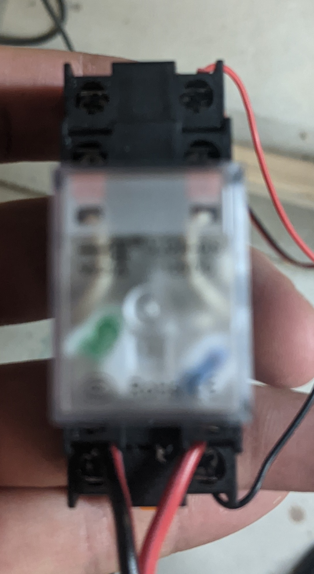
-:eight_spoked_asterisk: Mechanical relay
-:eight_spoked_asterisk: 12V power supply, I used this transformer

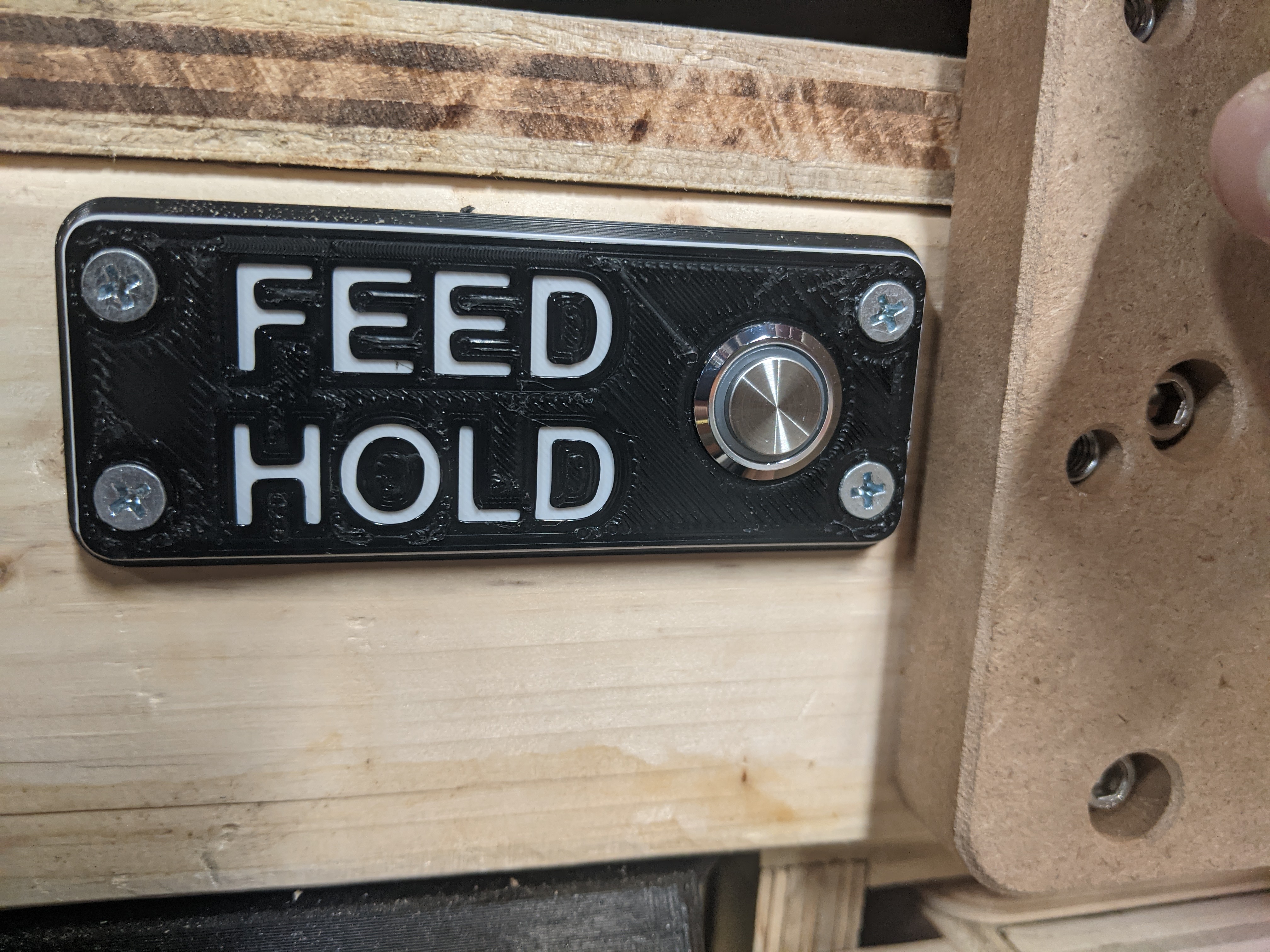
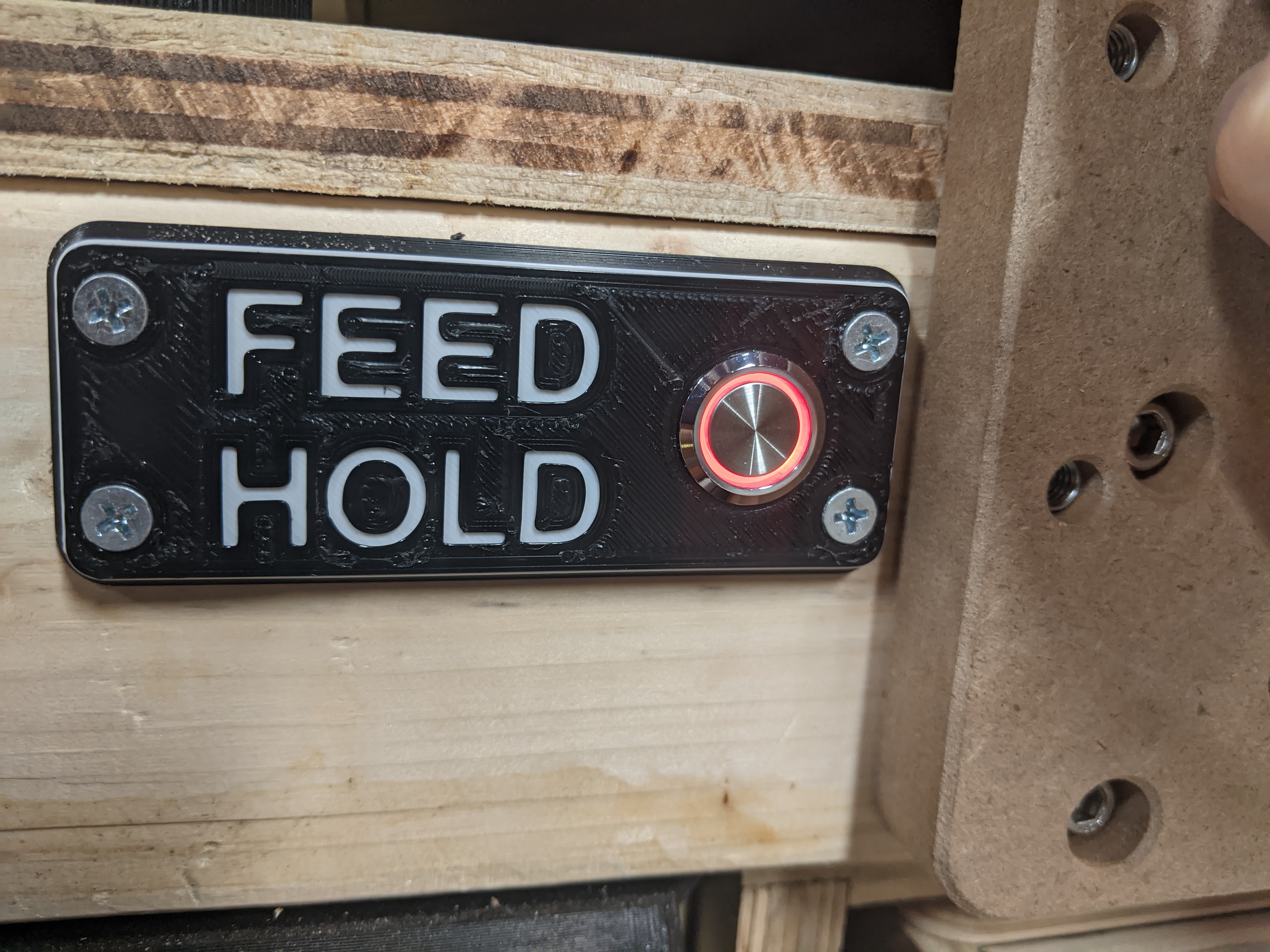
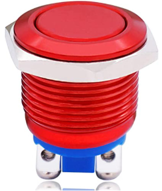
I decided to go fancy and use a latching push button switch with a red LED light when activated. This is what I bought. Not necessary, and adds some extra parts, complexity, & steps. If you do not want this, skip to step 3 for a regular switch w/out LED.

Steps:


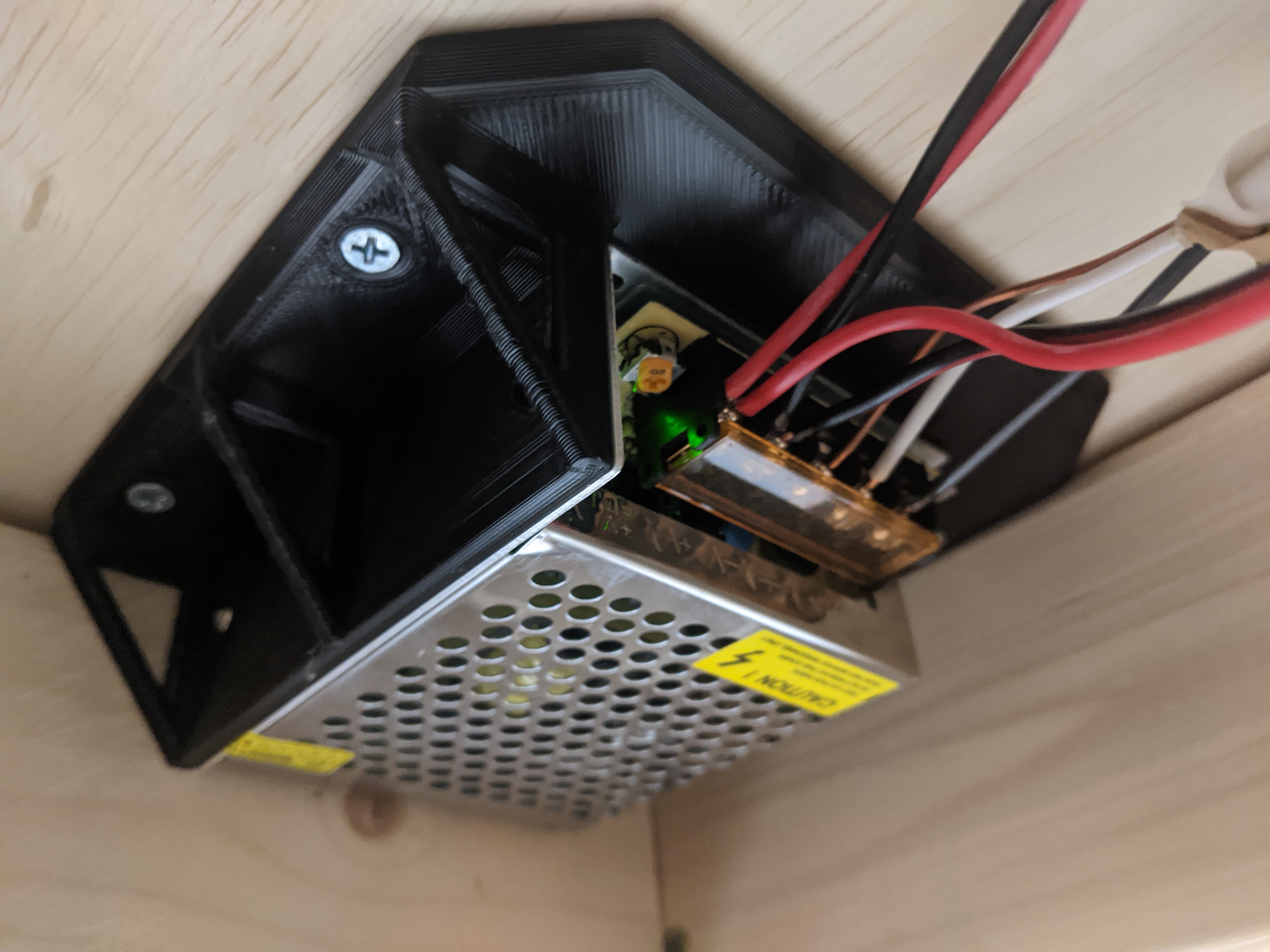
  1. You need a 12V power supply for the light on the switch (Or whatever voltage for the switch you may purchase with a light). What I did for this was to purchase this 120VAC to 12VDC power transformer. Here is my setup:

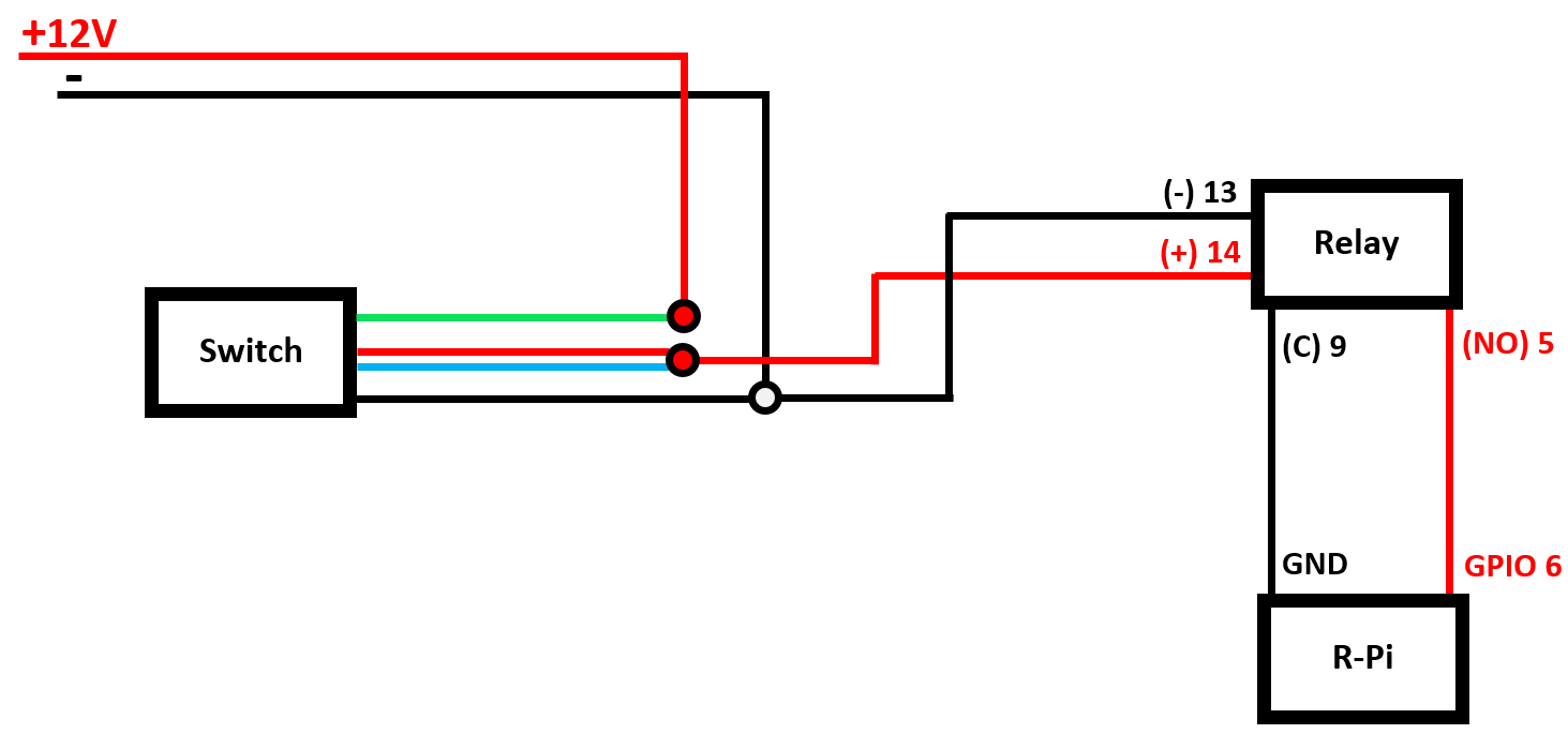
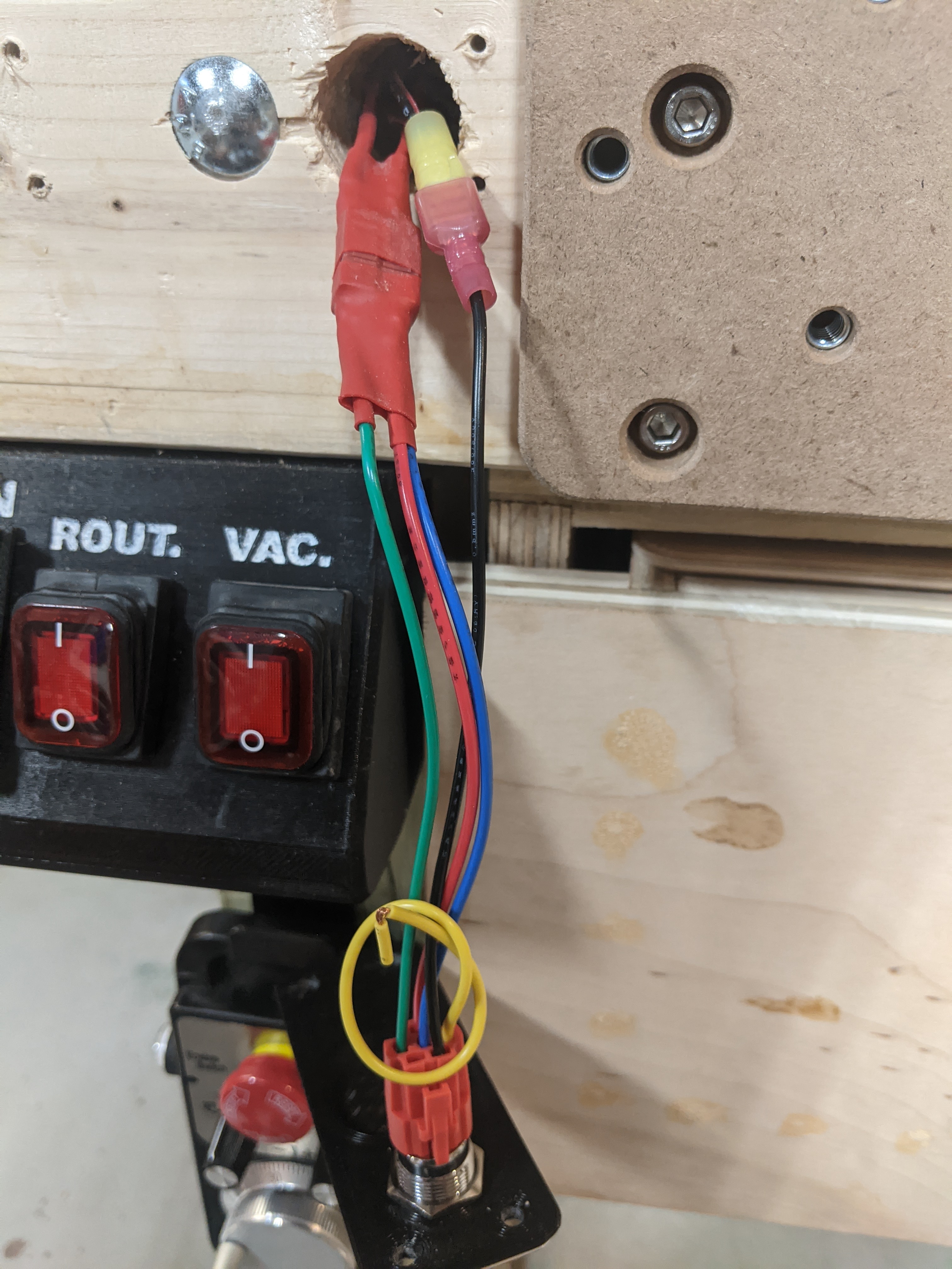
  1. Run your 12V output wires to the switch wiring, then run that output to the relay.
    See the following simple wiring diagram: (Based on my setup)

    **Make sure you wire the output wires of the relay to the normally open(NO) side… DO NOT use the normally closed(NC) side. I initially used this, but due to the function of the relay, It doesn’t perform reliably. When I released the switch with it wired to normally closed(NC), the spring back of the contact would ever so slightly “bump” or “bounce” off the contact, creating a moment where it would “double switch” and not properly function. Keeping it on normally open(NO) does not have this issue because the coil pulls the contact with enough force that there is no bounce back. When it is released, it doesn’t matter because when it bounces off, it is open either way.

  1. This is where you can begin if you don’t bother with a lighted switch, making it much more simple.
    Whether you are using a lit switch or not, you have 2 options:
  • Use a single latching switch (feed hold on activation, resume on release)
  • Use two momentary switches (One for dedicated feed hold, the other for dedicated resume)
    image image
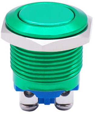
    I actually purchased these for the second option, but decided to opt for the first option in the end.
    ~
    The code I posted in step 4 is only for the latching switch. If you would like the option for the momentary ones, you will have to modify the code to meet your needs.
    ~
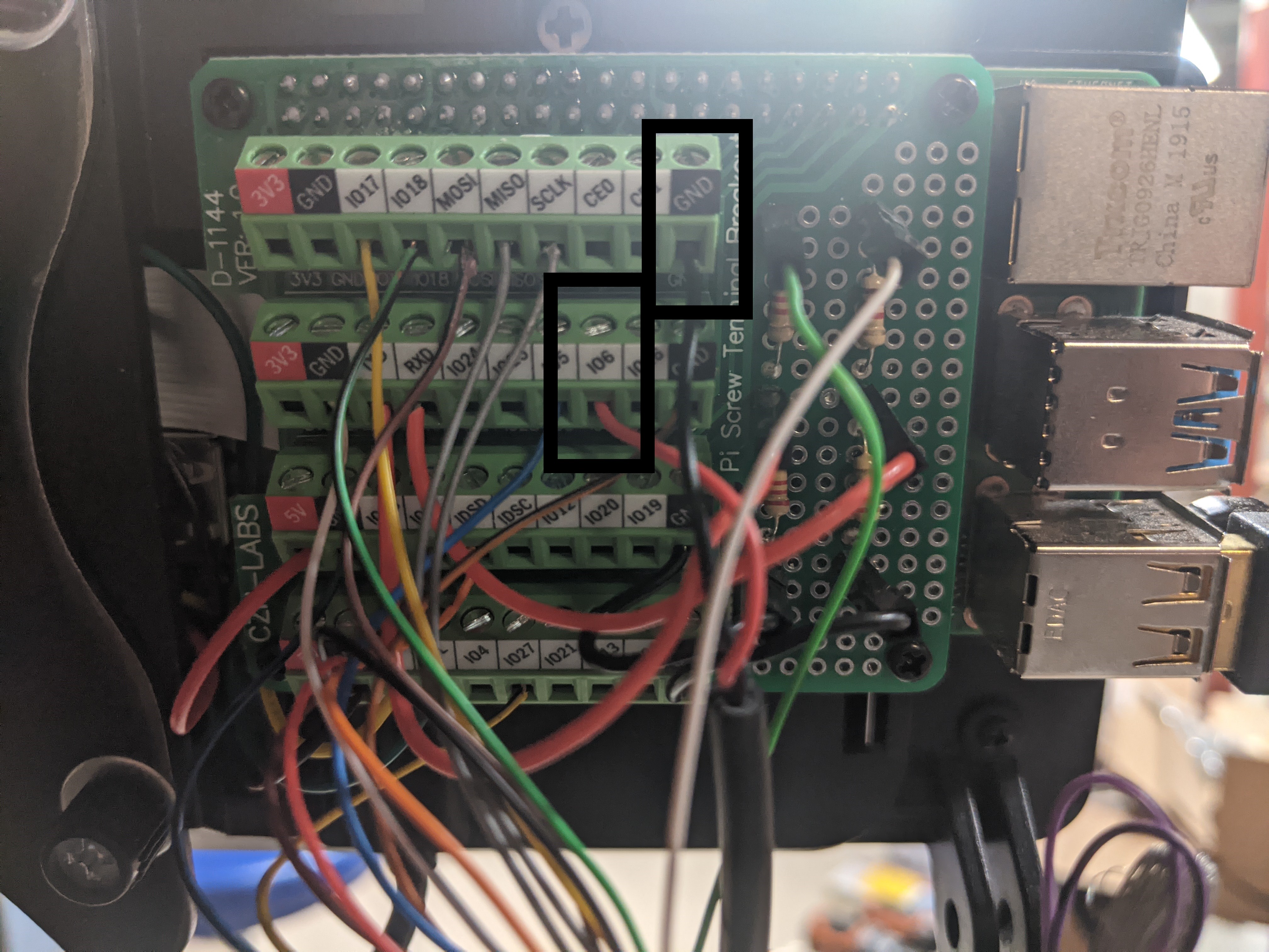
    For the latching, you will simply need to attach one wire to GPIO6 (or whichever pin you choose, see step 4 for elaberation), then the second wire to any ground(GND) on the raspberry pi pins.

  1. Now, the coding… I must admit that I am not at all proficient with coding, and I can only really modify existing code by staring at it and figuring out what the variables/functions do :laughing:
    ~
    With that being said, you need to follow Julien’s steps to get CNCjs to communicate with this code, so I will not spend time explaining how to get that working. In case you missed it, here is a link to his thread on that.
    ~
    Here is my modified code:
    cncjs-pendant-raspi-jogdial - KevinCarr1996 MOD.zip (5.4 KB)
    This code if has been modified from Julien’s original code to be in inches, and other slight changes to meet my preferences.
    If you already have his code, and don’t want to change anything else on how it works, just cut and paste the “buttonEStop2” variable and functions to put in your existing code. (Use find command to search all locations in the document)
    ~
    You must also add a “6” to the /boot/config.txt file on your raspberry pi from what Julien had mention in his post —> gpio=17,27,22,10,9,11,0,5,6=pu

Any GPIO pin can be used; I just happened to use GPIO6.
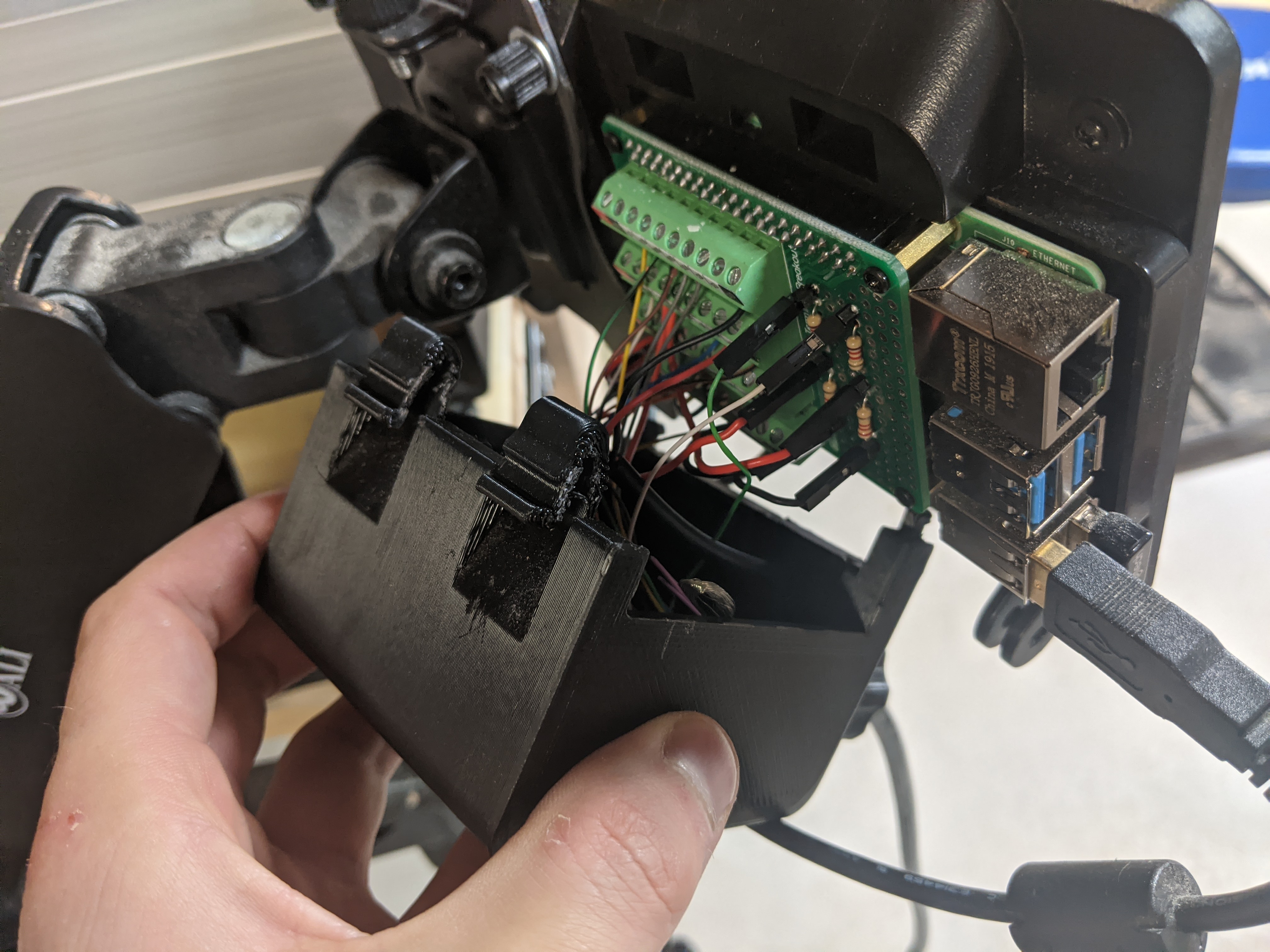
Here is my wiring:


I think that just about covers everything I did! Here’s a little video of when I got it working:

Here’s a ZIP file including STL’s with the following associated 3-D printed parts:

  • 12V power supply mounting plate
  • 7" R-Pi touch screen case back plate for pendant wires
  • simple feed hold switch housing

Shapeoko 3 Feed-Hold 3-d print parts.zip (938.5 KB)

Hope this helps some of you guys!! :grinning:

I’d love to see other’s work on this and especially if someone decides to work off of it to create further conveniences!

5 Likes

thank you for sharing !
I can reopen this thread anytime if needed.

2 Likes

This topic was automatically closed after 30 days. New replies are no longer allowed.