Hi folks,
Recently I was inspired by this post (thanks @npross!) and bought one of these pendants that have two multi-position switches, a handwheel, and an enable pushbutton
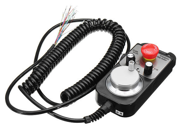
This post is intended to document how I interfaced it with the Shapeoko, in case anyone wants to make a similar setup. This is completely overkill if you just want to trig predefined keyboard shortcuts on your favorite G-code sender, a USB or wireless keyboard will be much simpler to use. But I wanted to have the ability to map the pendant controls to run arbitrary G-code snippets on the Shapeoko.
The pendant I bought came with a wiring sheet, which spared me the effort of figuring out which wire corresponded to which part of the pendant:
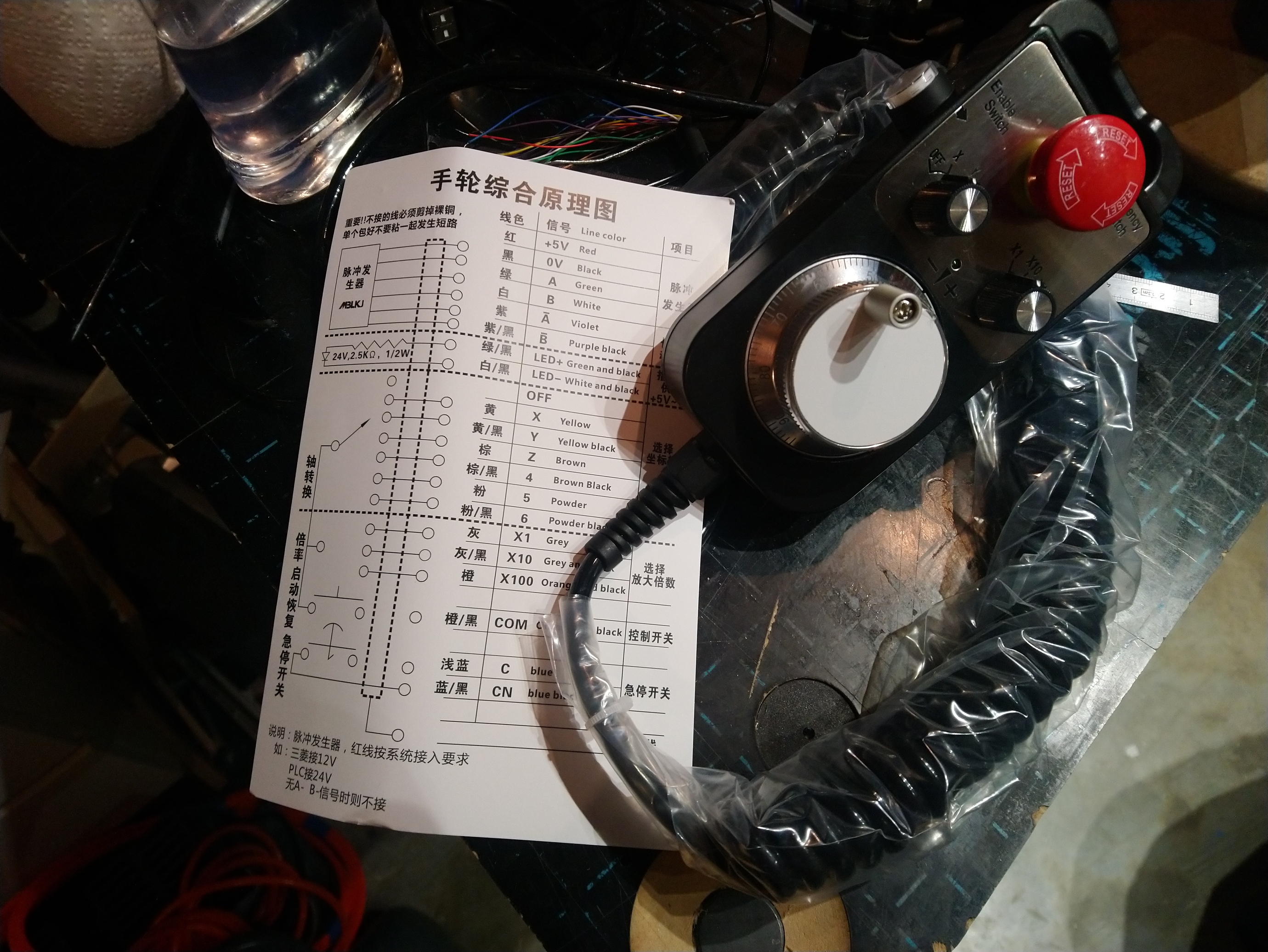
(the Aliexpress link to this pendant is in the original post, but there are many variants of this around)
I use CNCjs as my main G-code sender, and there happens to be a few examples here of code to implement CNCjs pendants (they use the “Node.js” framework). CNCjs is actually a web server, and the user interface itself is just a web page running in any browser, either locally on the same machine CNCjs runs on, or on a remote computer.
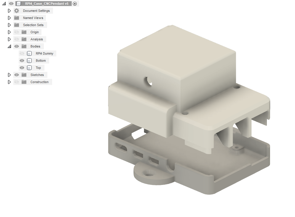
I decided to use a Raspberry Pi 4 mini-computer to install CNCjs as well as the pendant. Any Raspberry Pi model could work, but the oldest models may have trouble running CNCjs efficiently.
I installed a stock “Raspbian” image on the SD card, did initial configuration, and proceeded to install CNCjs using these instructions.
I connected the Shapeoko to a USB port of the Raspberry Pi, launched CNCjs from the command line:
cncjs &
By default, CNCjs listens for incoming connections on port 8000. I was then able to access the CNCjs user interface by connecting to
http://[IP address of the raspberry Pi]:8000
So far so good.
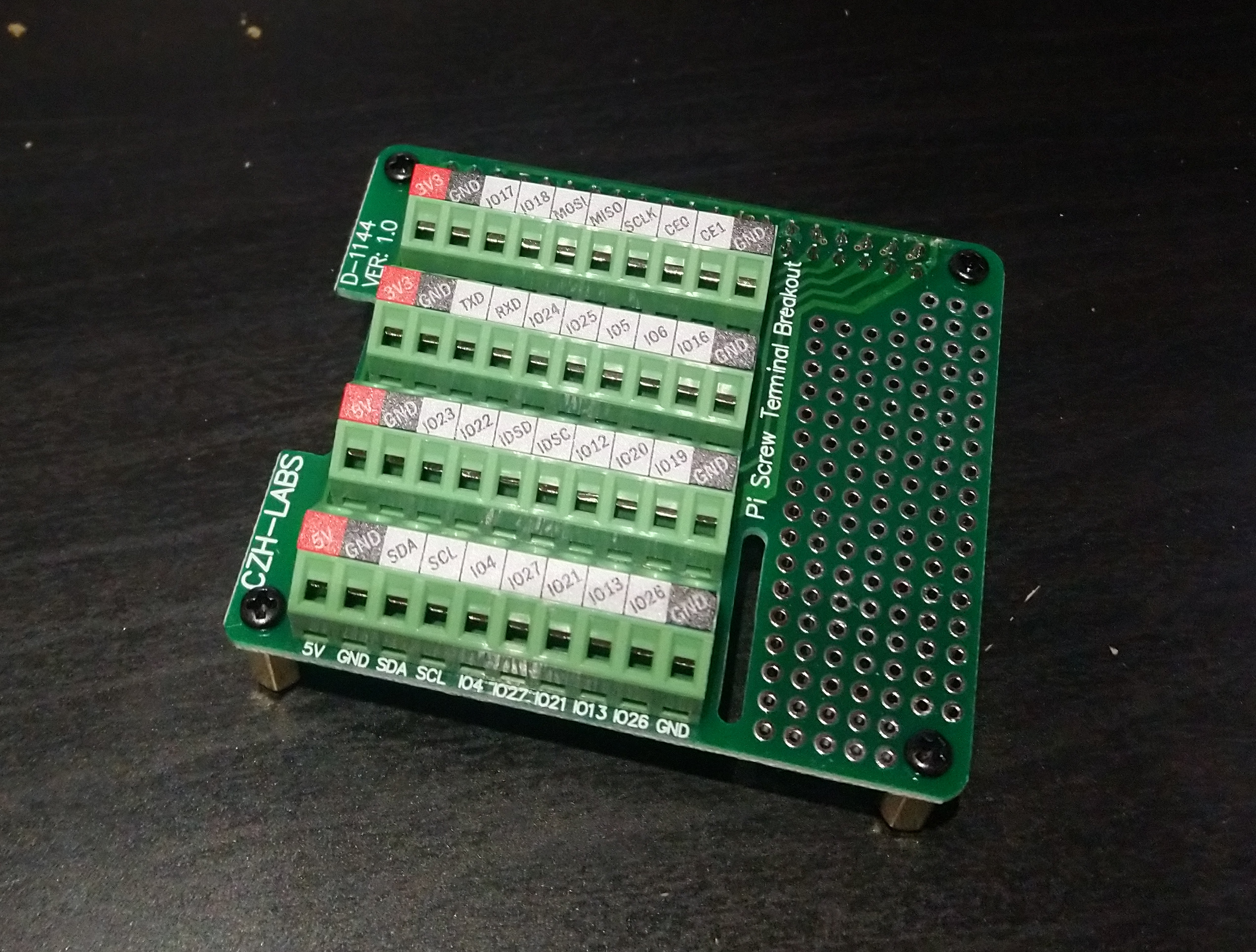
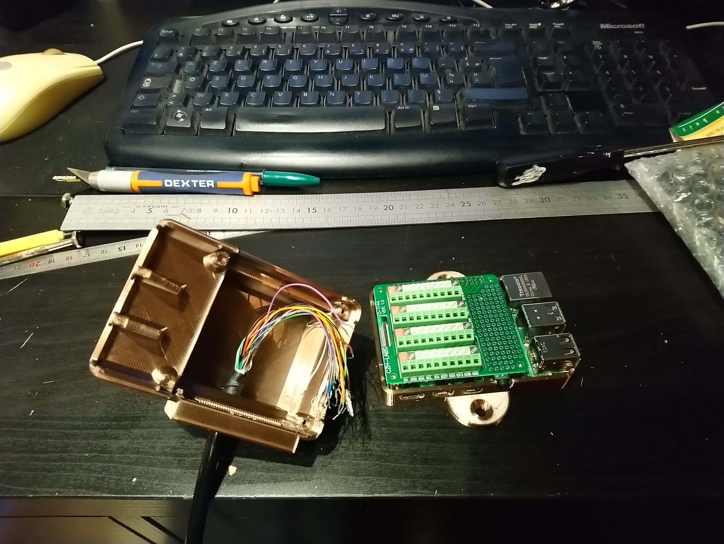
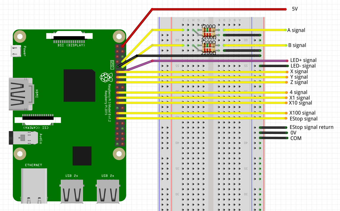
Next, I connected the pendant wires to the Pi like this:
Left column from top to bottom
pin 9 / GND
pin 11 / GPIO17 = X
pin 13 / GPIO27 = Y
pin 15 / GPIO22 = Z
pin 19 / GPIO10 = MOSI = 4
pin 21/ GPIO9 = MISO = X1
pin 23 / GPIO11 = SCLK =X10
pin 27 / GPIO0 = ID_SD = X100
pin 29 / GPIO5 = EStop
Right column from top to bottom
pin 2 / 5V = handwheel power supply
pin 8 / GPIO14 = TXD = A
pin 10 / GPIO15 = RXD = B
pin 12 / GPIO18 = PCM_CLK = LED+
A few notes on the pendant signals:
- 5V is used as an input voltage for the internal handwheel mechanism.
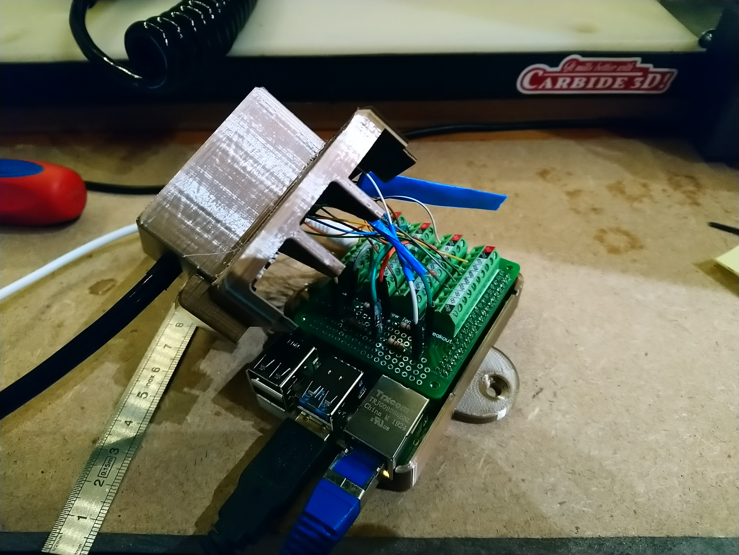
- the “A” and “B” signals are connected to the handwheel, and allow one to determine when the wheel is turning, and in which direction. They are supplied by the 5V input, but a Raspberry Pi has 3.3V inputs, so a simple voltage divider with two resistors is used to bring voltage down to around 3.3V before it enters the Pi (I used 1200 ohm and 2200ohm resistors for this).
- the pendant has an LED, that can be turned on and off
- the X/Y/Z/4 signals come from the left switch/selector.
- the X1/X10/X100 signals come from the right switch/selector.
- there is a signal for the E-stop pushbutton
- the pendant has an enable pushbutton on the side, but no dedicated signal, it just enables/disables other signals.
I started from the cncjs-pendant-raspi-gpio boilerplate code, and adapted it to my needs. The resulting cncjs-pendant-raspi-jogdial code is available here.
A disclaimer for web developers out there: this is my first timing coding in Javascript, so I’m sure it violates half of the best practices. I commented it (a lot) so hopefully if someone reuses it he’ll be able to figure it out easily.
What the code does is connect to the CNCjs server, and send “write” operations to send specific G-code commands to the Shapeoko (CNCjs server acts as a gateway)
The code implements this logic:
- the enable button needs to be pushed for anything to happen. The LED on the pendant is turned on when enable is activated.
- if wheel movement is detected
- a short turn will trig a single jog step (e.g. G91 G0 X5)
- a continous rotation will trig a smooth jog (e.g. by sending $J=G91 G21 X10 F2000 repeatedly)
- stopping the rotation will trig the sending of a jog cancel command (0x85)
- the left switch is read to determine if the jog should happen on X,Y, or Z axis
- the right switch (X1/X10/X100) is read to determine
- the jog step when doing a single jog step (currently mapped to 0.1mm, 1mm, and 10mm)
- the jogging speed when doing smooth/continuous jogging (currently mapped to 100mm/min, 1000mm/min, and 5000mm/min)
Note : I implemented it all in metric units (millimeters)
For the code to work, ¨some of the Raspberry Pi GPIOs used need to be configured to activate their internal pull-up resistors, I did this by editing the file /boot/config.txt and adding this line:
gpio=17,27,22,10,9,11,0,5=pu
(followed by a reboot)
Note: input pins 13 and 19 for signal A / signal B do not need any specific configuration, as they have an internal pull-down by default, which is the right configuration for these 5V inputs.
The pendant is then installed by copying the cncjs-pendant-raspi-jogdial directory somewhere on the pi, entering the directory and typing:
npm install
Then it’s executed using
node bin/cncjs-pendant-raspi-jogdial
and then selecting the USB port on which the Shapeoko is connected to the Raspberry Pi (/dev/ttyACM0 in my case)
And voilà:

EDIT: here are a copy of the instructions to make cncjs and the pendant code start automatically when the raspberry pi is turned on, using the “pm2” utility:
First install PM2:
sudo npm install -g pm2
pm2 startup
sudo env PATH=$PATH:/usr/bin /usr/lib/node_modules/pm2/bin/pm2 startup systemd -u pi --hp /home/pi
Start cncjs and the pendant:
pm2 start $(which cncjs)-- --port 8000
pm2 start "node /home/pi/cncjs-pendant-raspi-jogdial/bin/cncjs-pendant-raspi-jogdial --port /dev/ttyACM0"
(you will need to adapt the /home/pi/… path to match your setup, and the serial port may not be named /dev/ttyACM0 in your case either)
Check everything is up and running, and save this configuration such that it starts automatically upon next boot:
pm2 save
I’ll work on a more permanent wiring scheme, and edit this post later accordingly.