I have been having this issue for a while now with the adv. V-carve feature and was wondering if anyone else has had this issue and knows how to fix it.
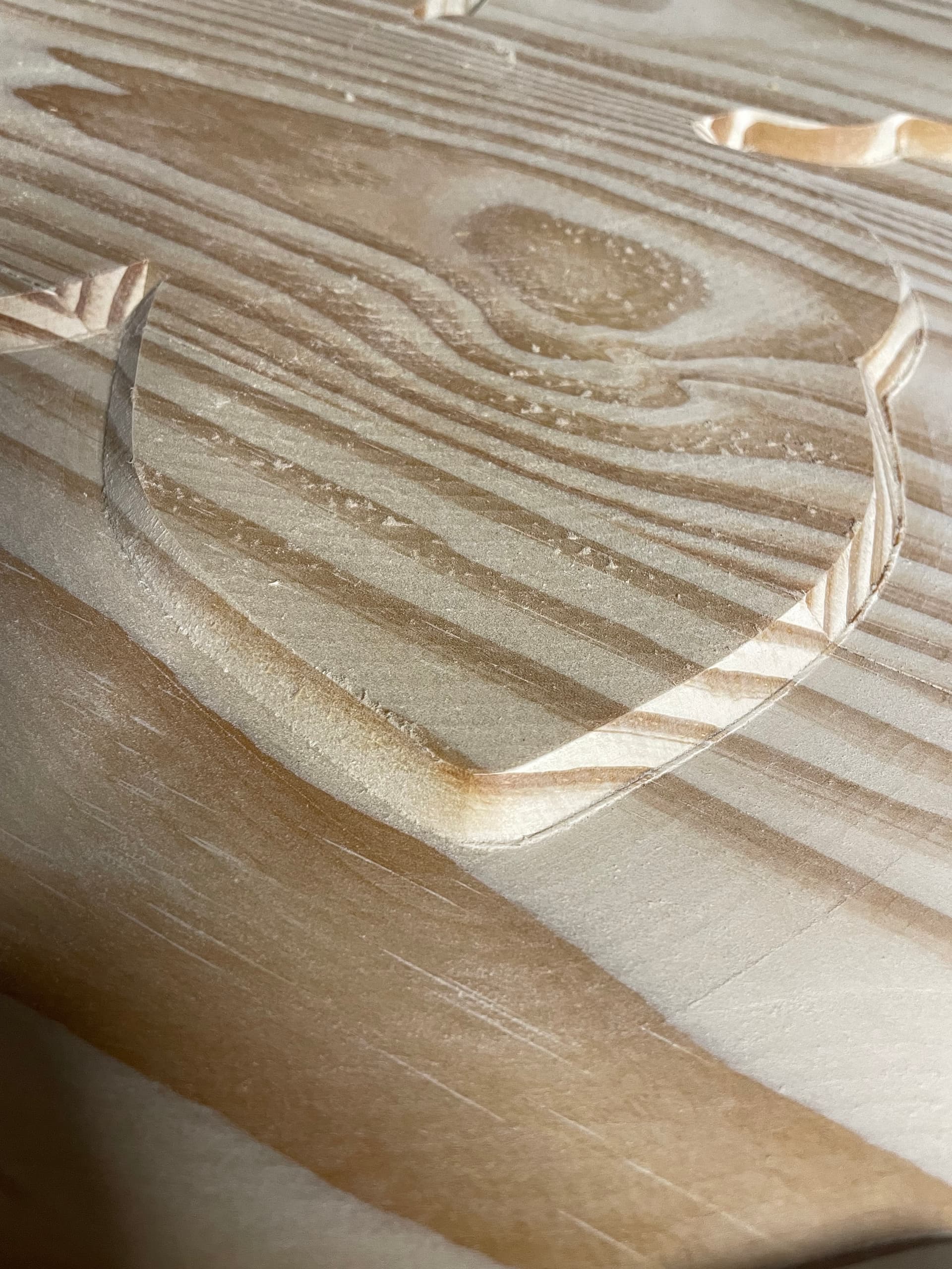
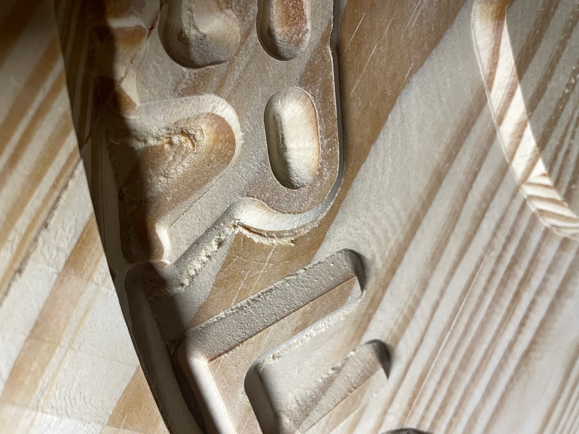
Every time I do an advanced V-carve operation, I end up with this weird ledge on the bottom face that is created between where the V-bit and regular bit meet.
Here are a few fixes I have already tried:
switching between different types of bits for both bits
changing feed rates
made sure the work is held firmly in place
adjusted belts
Note* I noticed that it seems to mostly be on a specific side of the work as you can see in the photo of the acorn the little ledge on the bottom face is only on the right side of the acorn. On the machine, this is the direction of the Y axis that points towards the entrance to the machine.
Have not trammed the MDF filler strips (if these are the pieces of MDF that sit on the bed of the machine) I have not done this yet because I do not know how to tram the entire piece of MDF because each piece is bigger than the cut area so if I just run a surfacing pass on the entire bed, I will be left with just a big square bowl cut into my mdf, idk how to get around this
II do not know the name of my z axis, but when I set up the machine, it’s the one with the picture that has the notches near the screws on the side on the front plate of the z-axis carriage. When I look on the website I do not see my z axis listed, so I’m guessing its old.
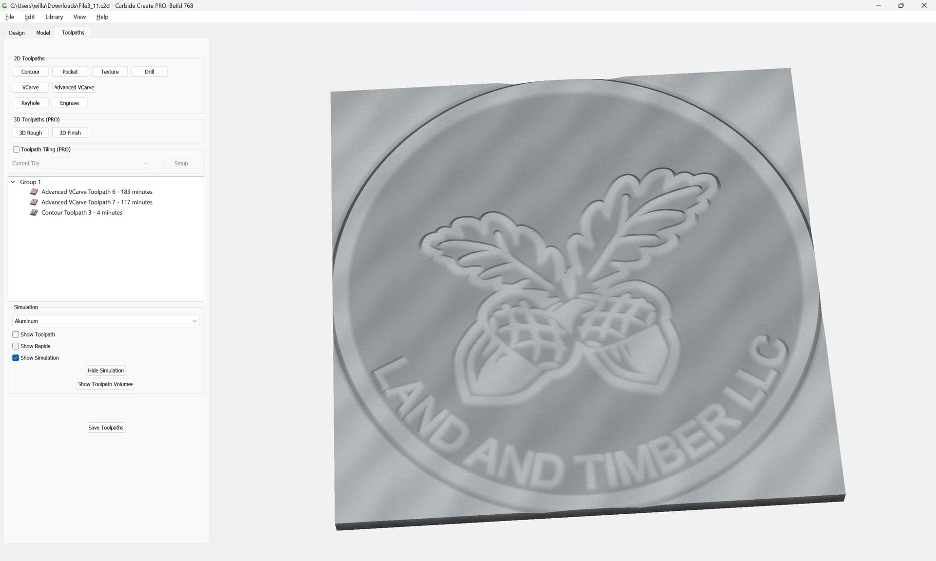
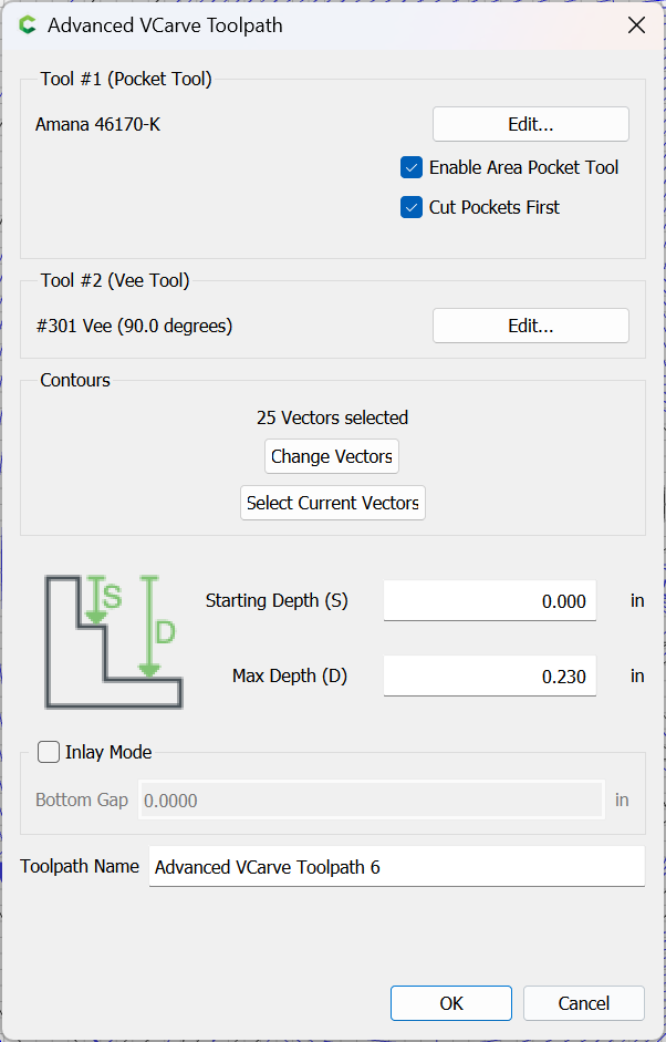
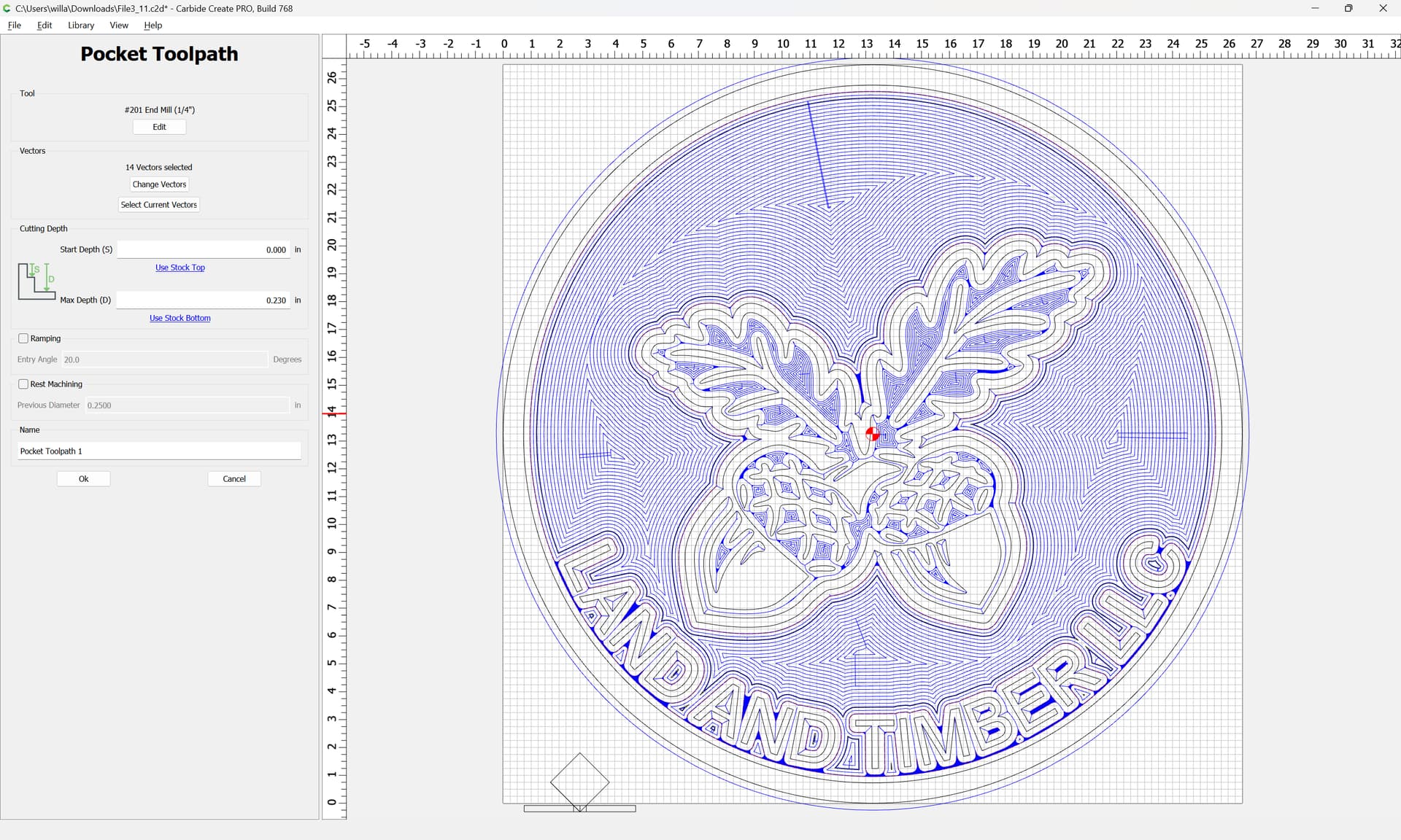
Max depth is .23 and the max depth per pass is 0.06 for the regular bit and 0.1 for the v-bit (settings from carbide create)
In this image, I cut the pocket first and then the v bit, but I get the same result if I cut it the other way around as well.
Tramming is essential to getting everything square and level. I understand that you will end up with areas that the bit can not reach. You will not be able to place your part in that area as it will not cut. Living in the Seattle area my MDF swells due to the humidity. Depending on what I am cutting, I sometimes need accuracy to .002. So I end up leveling my MDF weekly to get that accuracy.
One thing you can do is move you machine to middle front. Lower “Z” to the strips, set zero. Retract, move left or right lower to surface again and see if zero height is different. Check various spots on your MDF. This will tell you where it is off and by how much.
Also getting the router/spindle square to the bed is important. With my requirements of .002, the first time is an arduous task. If my requirements were less it would not be that hard. On the Carbide YouTube page there is an excellent video for tramming the Router/Spindle.
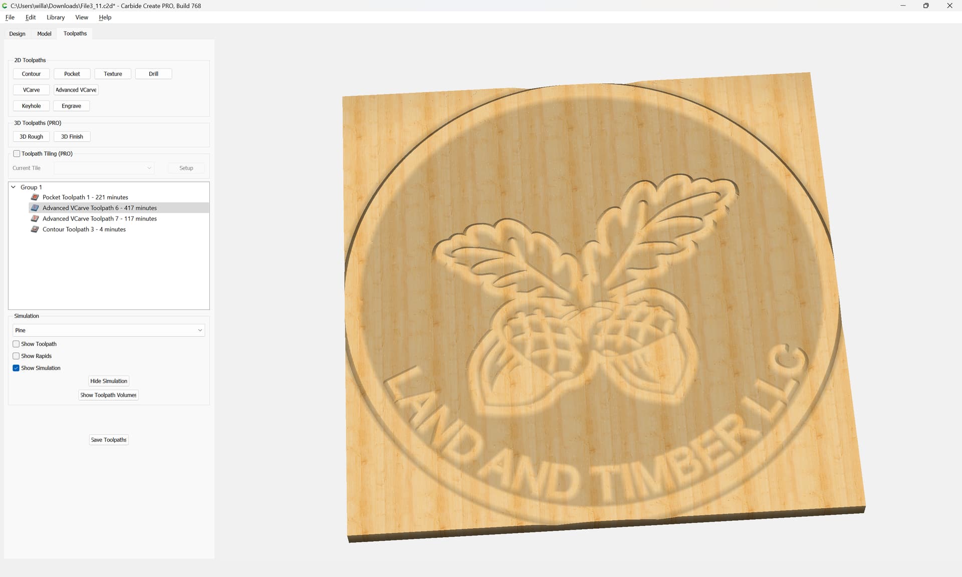
For a 26 inch diameter sign in softwood, cut with a 1/4 inch end mill and a 90 degree V bit, I think your surface looks decent and I dont think I would be too concerned about surfacing / tramming yet. The ridge where the two paths meet (which I have seen before), is the main issue. It looks more pronounced when cutting across grain which hints at tool deflection of the v bit. If you haven’t yet, you might check/adjust the two bottom v wheels where the Z carriage rides on the X extrusion and the four bottom v wheels where the X carriages ride on the Y extrusions. Also, be sure your belt tensions are similar to each other. If one seems not as snug as the others, tighten it.
I believe that’s the original flat-plate belt-drive Z-axis.
It requires a delicate touch — if upgrading to a Z-Plus or HDZ isn’t an option one thing to consider is to see if someone who has upgraded here has a newer belt-drive unit with the shorter plate w/ curved edges which they can sell to you.
Do you think it could be that the zeroing of the machine got thrown off somewhere? After the initial pocketing of the adv vcarve I turned the whole machine off and came back the next day. Maybe the zero was not accurate when I came back the next day (I did not re-zero the machine)?
Thanks for your help. I will tram the MDF after this project and try that trick using carbide motion to measure the height differences! I have had issues getting the router to be square to the bed. I even bought the 123 blocks like in that video you mentioned. Maybe the whole time the MDF filler boards were not level so I was only leveling to one specific area of the machine…
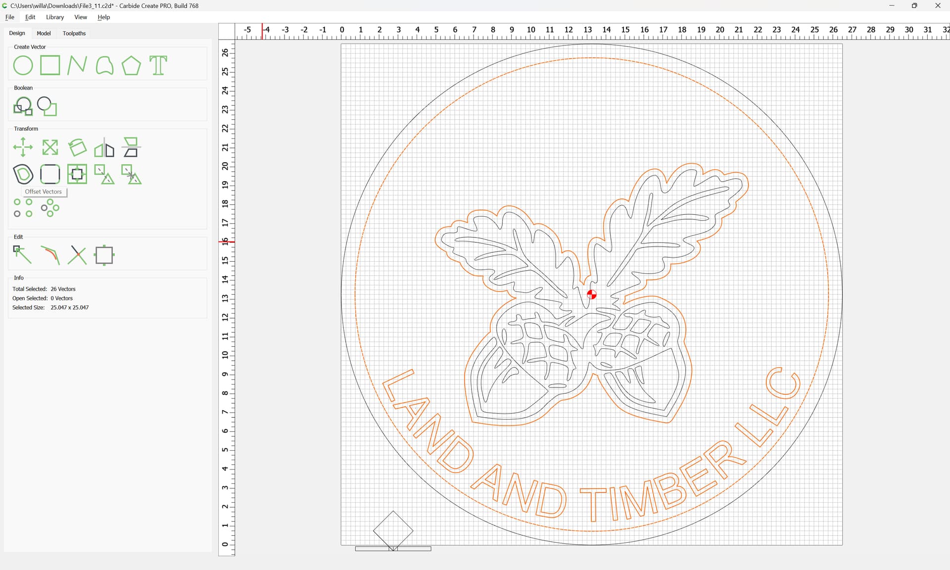
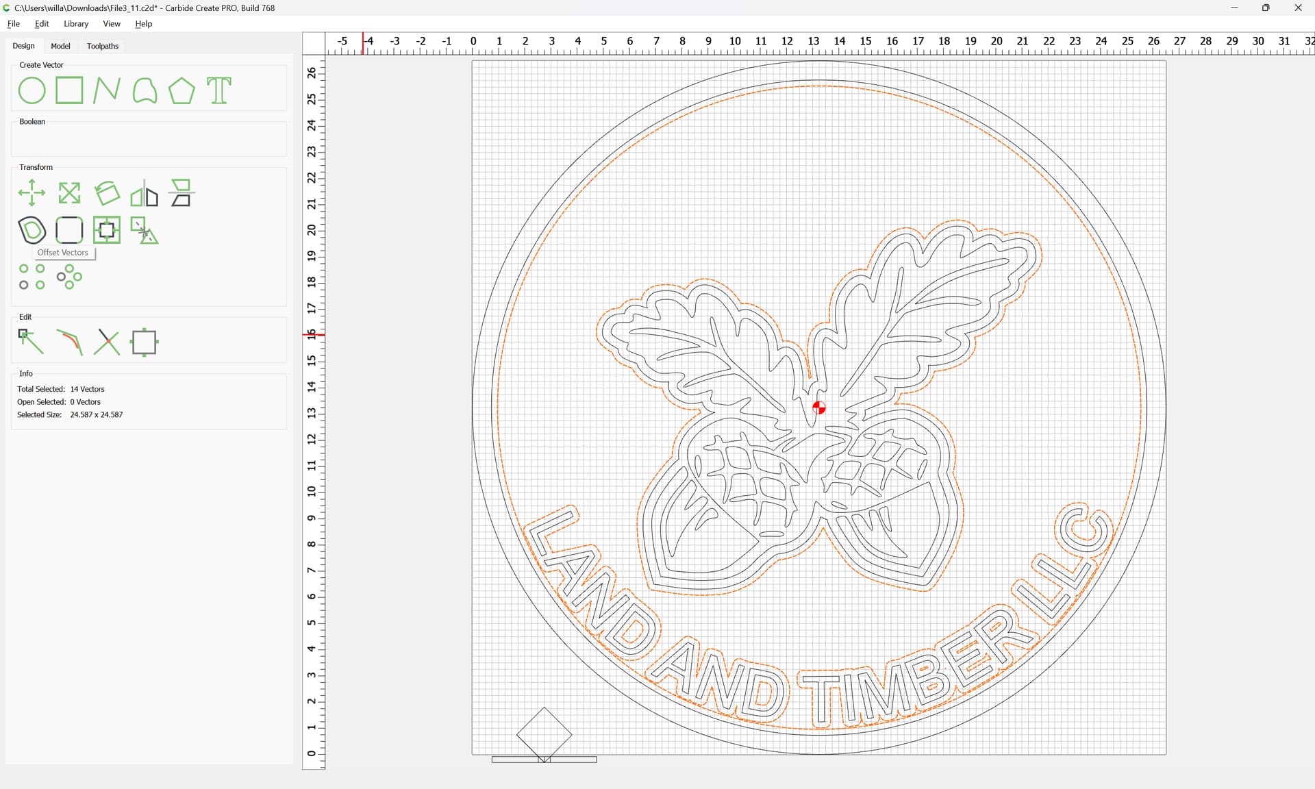
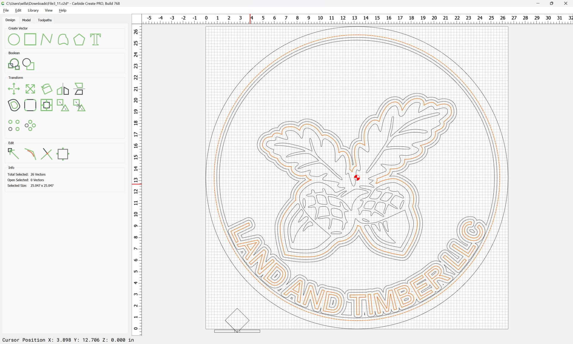
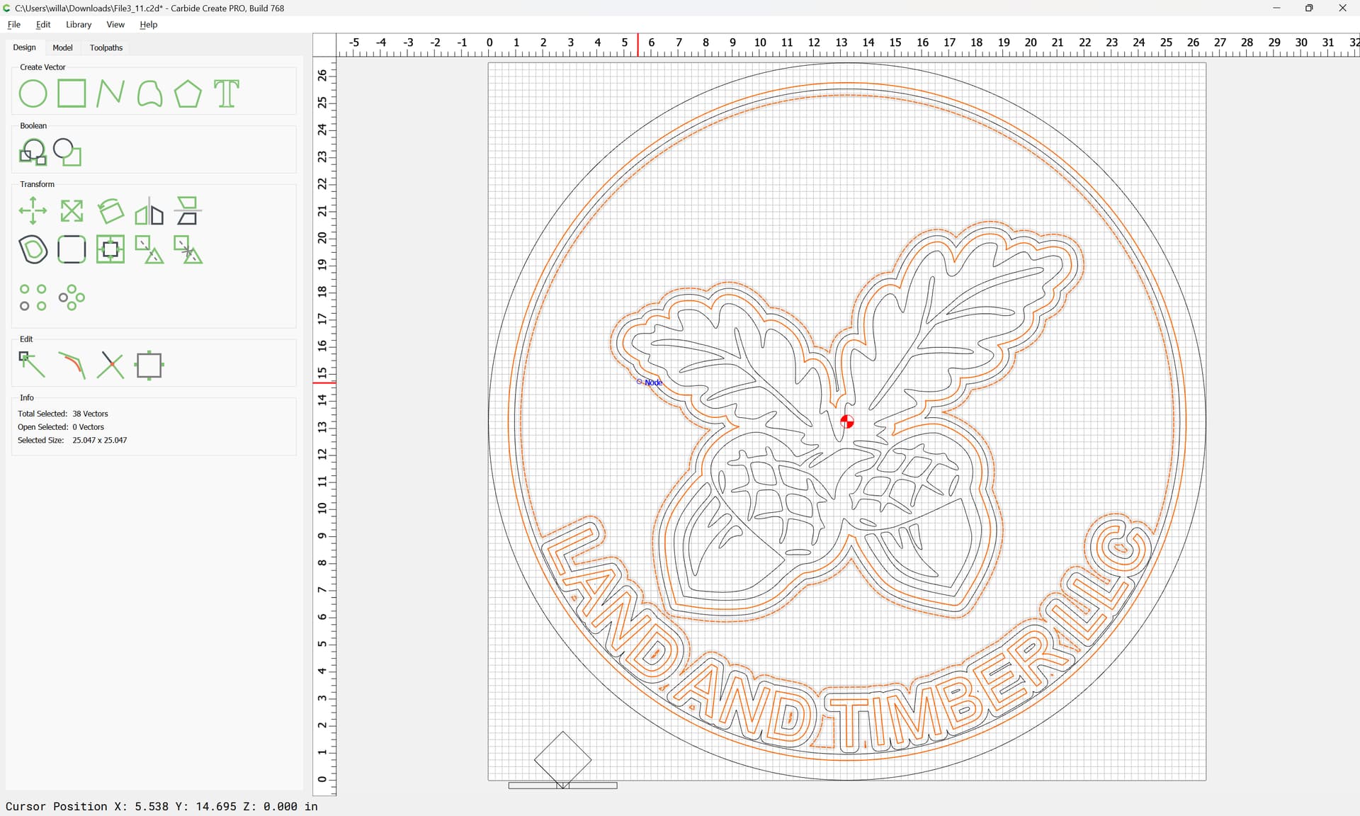
It has a twisting rod that the z-axis moves on if that helps. I do not see any belts. But, I had a question regarding a post about rest machining for Adv-Vcarve (or really the ability to use multiple-bit sizes on adv-vcarve). I read your post and I was trying it out on this file but I keep ending up with this region between the bottom of the letters and the emblem near the top right leaf of the sign which I can not seem to cut out right. Could you take a look at the file I uploaded on this post and see if you can edit it with toolpaths to show how to use the inset adv v carve method you mentioned in a previous post (this post Rest machining with V-bits)? What’s odd about this cut I’m making is when I cut the acorn part, there is nothing wrong with it at all. It turned out great. It was just the letters that got messed up for some reason…
I will try this. moving the slats forwards and then backward to get the full y length cut and the I’ll take the right and left most boards and rotate them to the middle and cut them fully last. Thanks for this tip.
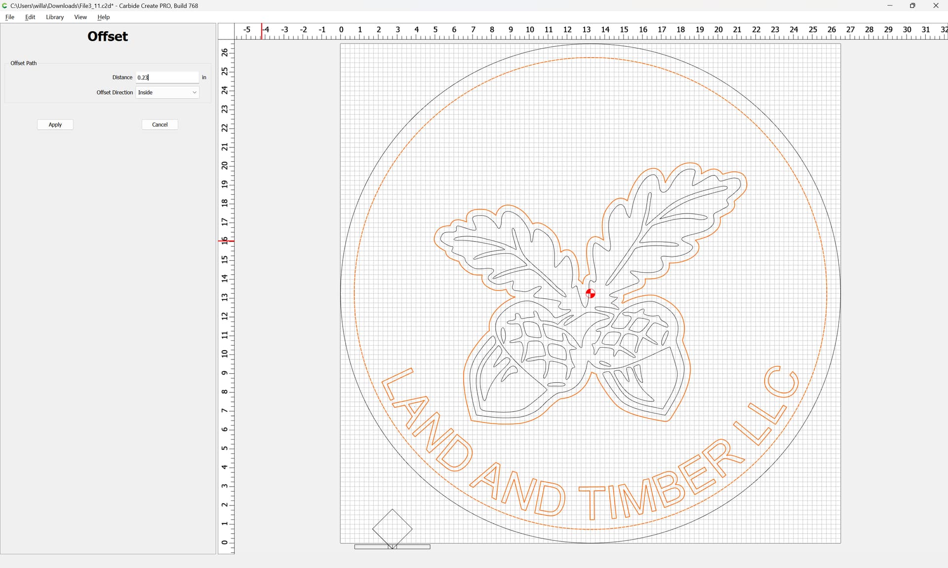
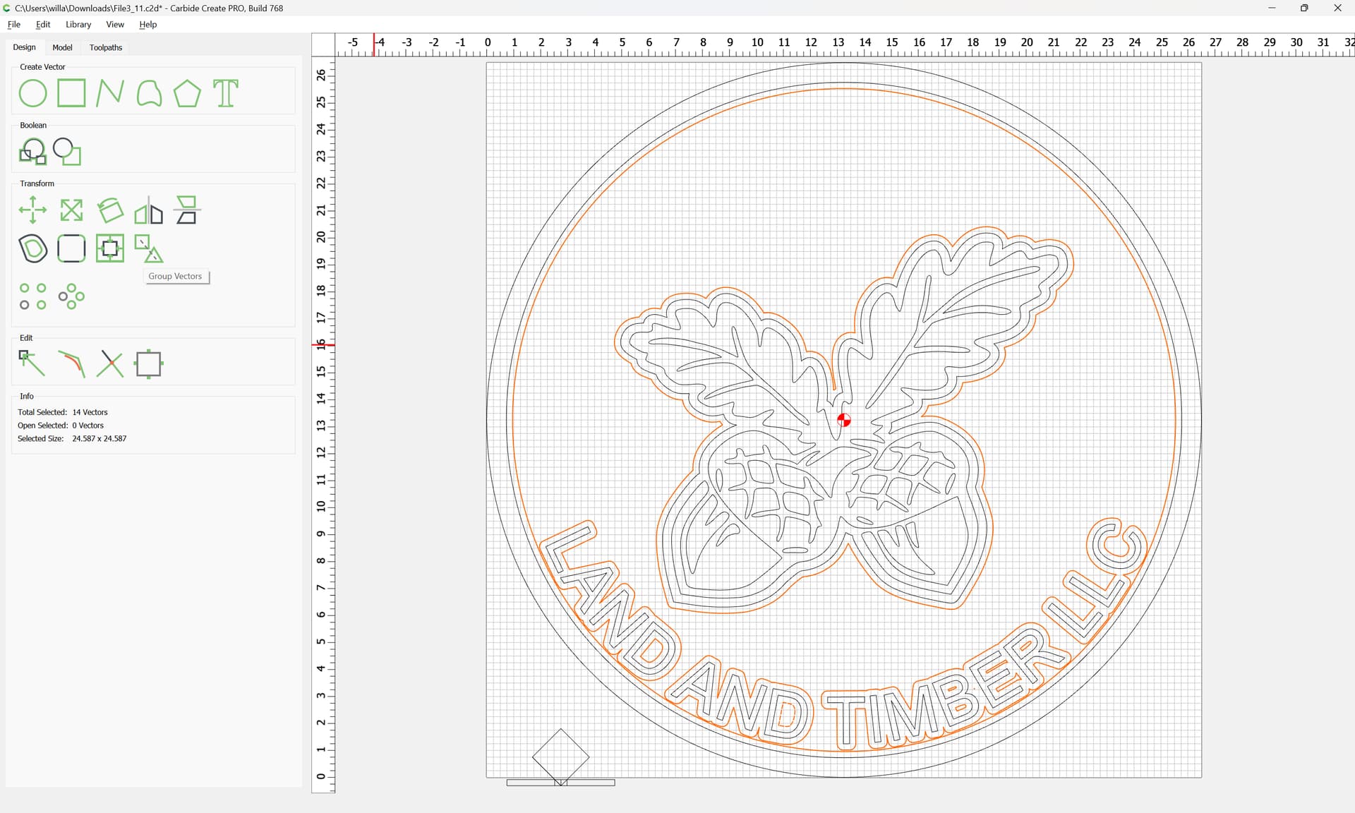
that way it will start w/ the small Amana, switch to the #301 for the first Advanced V carving, then continue with that tool for the second, then switch to the other tool after.
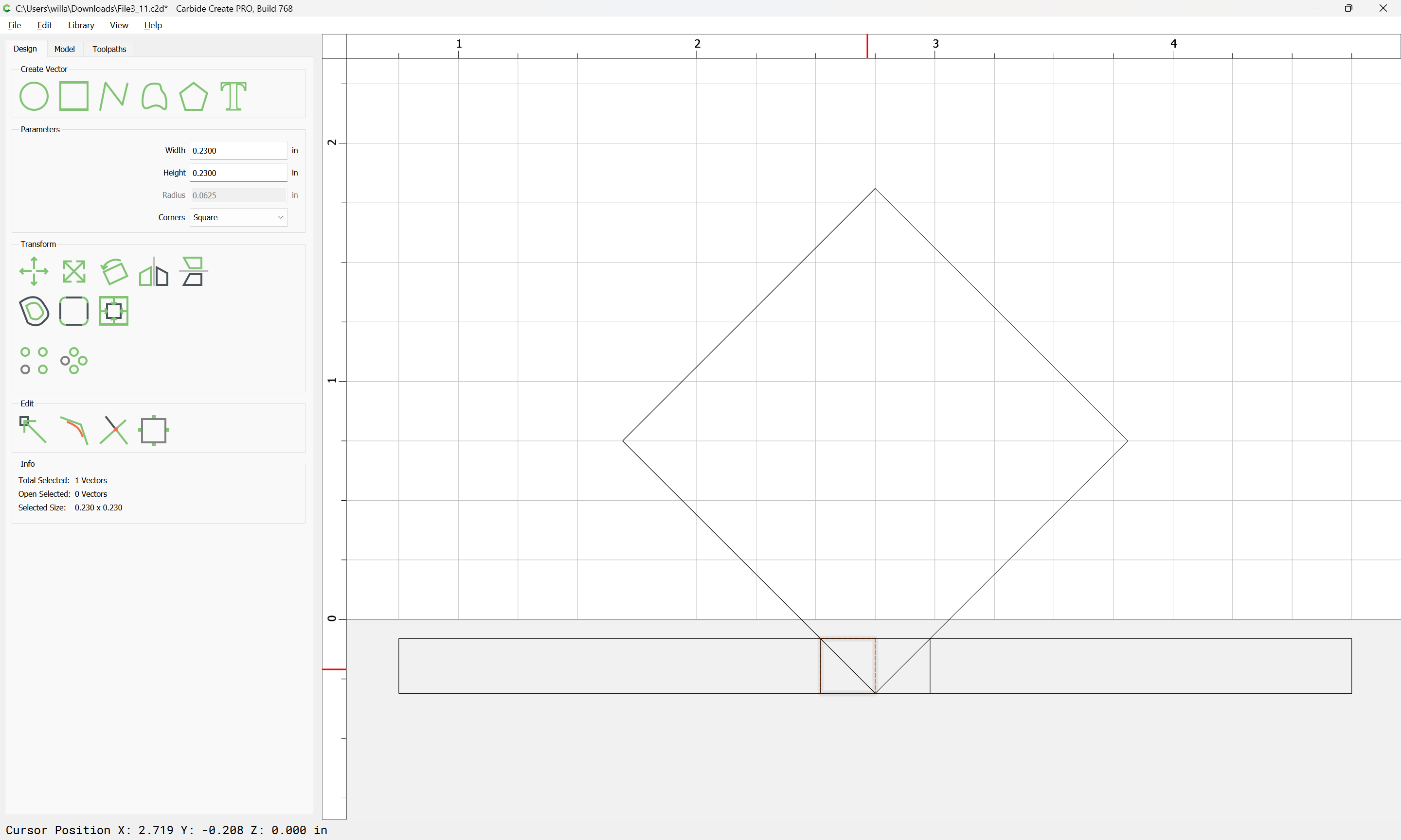
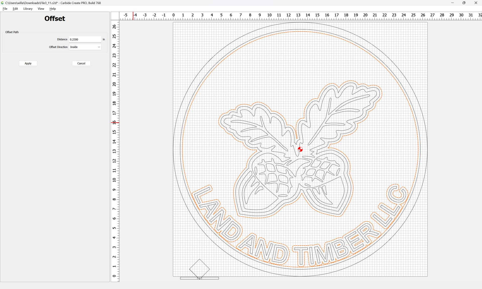
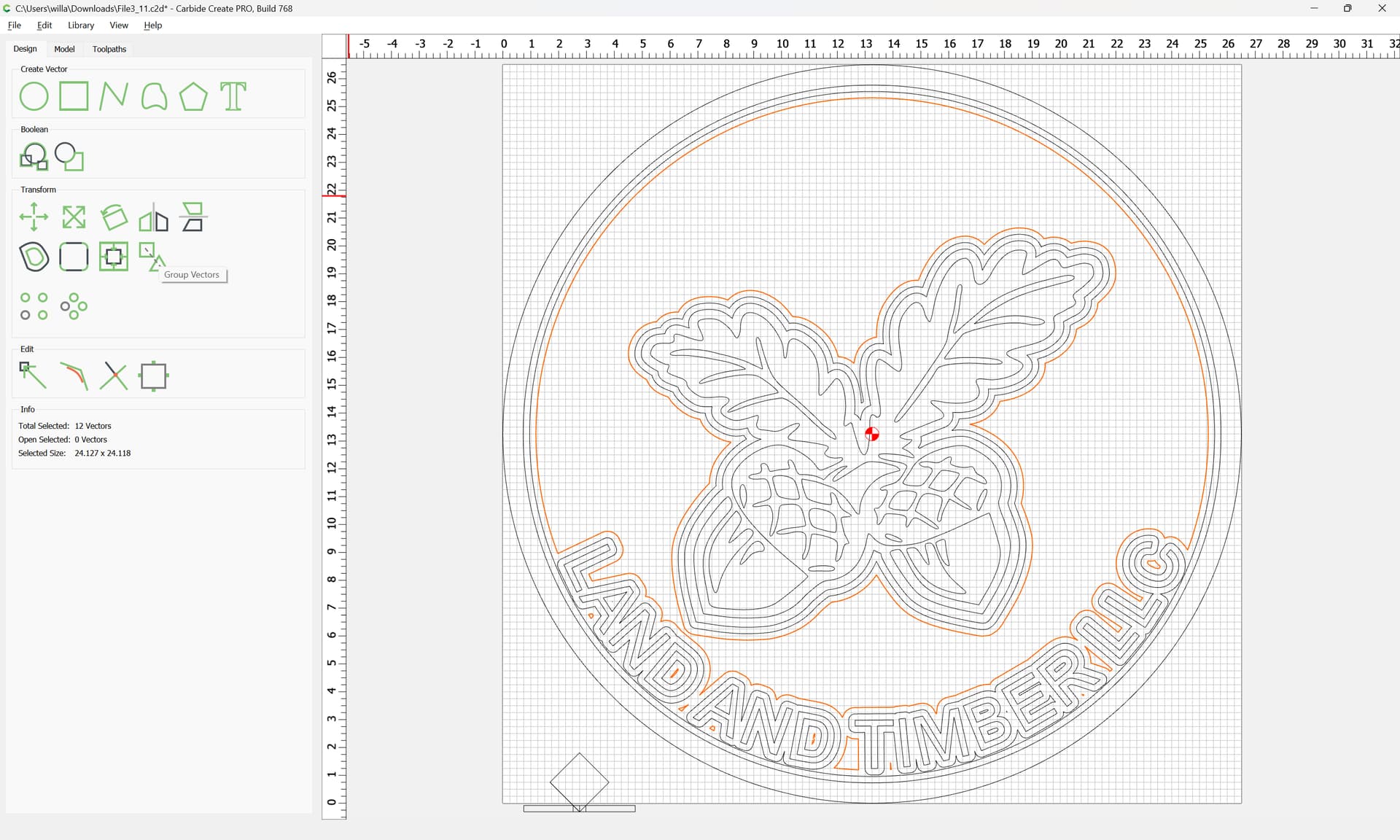
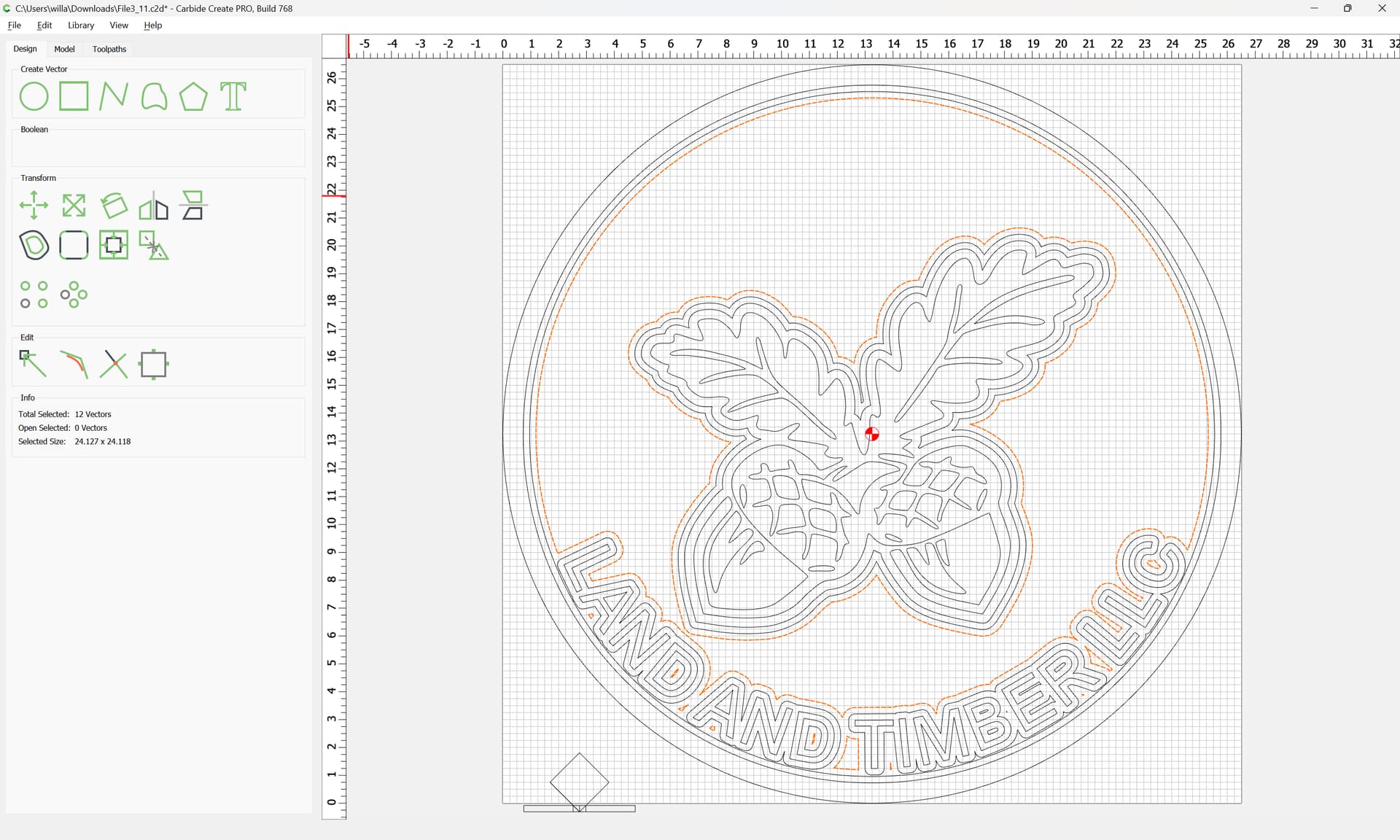
Since a 90 degree tool is being used, the distance to inset is equal to the depth being cut:
Perfect. Thank you for this! I’m still working on figuring out the original issue. I will update here when I have more info to provide after trying some of these fixes.
I am pretty confident this is not in the g code. I looked at the line segments for the 3 V bit paths and they share identical x y coordinates for all three passes, likewise for the 4 passes with the end mill.