Backlit wall panel/light thing (WIP / build log)

If you paint all the internal surfaces with good white paint that’s >95% reflective in the visible (and some in infra-red) band, that will reduce the hotspot appearance as light reflected back from the front diffuser will bounce off the backboard, at present it is dark MDF coloured.

A strip of sanded acrylic along each LED line would help to diffuse the rays from source as per the diagram Gary showed.

In that paper lantern I made I accidentally found the trick was to rotate the central LED lamp post 45 degrees so that the LEDs were pointing at the corners and the light falloff off axis was in the middle where the paper was closer.

4 Likes

There’s also this stuff, which would give you wonderful reflectance and no thickness costs. I would invert the LED strip onto a board sprayed with this, let the light bounce back through your Shoji paper and be done with it…I think.

3 Likes

Mount the LEDs on the opposite surfaces? Then you’ll get even reflection.

1 Like

A hot glue blob works pretty well too.

2 Likes

Yep, back in the days when you bought LEDs one at a time we used to sand the lens down flat and leave it rough for a diffused light from them… :older_man:

1 Like

That table could have made a very nice large trivet! But I think this transformation is better, haha.

3 Likes

So while I’m still considering doing the “acrylic & shoji sandwich” approach, I did do some tests based on the tips you guys gave me.

Here’s one way I could do the “flip the LED strips and have them reflect off the back”, by utilizing the width in between triangles

Sure enough, with this and using a white background (just some depron sheet I had laying around), nice uniform lighting through two layers of shoji

5 Likes

New problem.

At this point the final piece should look like this from the front,

with triangle recesses milled from the back for the acrylic/shoji sandwiches, and the LED strips standing on the “ridges” between triangles:

But so far I had overlooked the question of where to position the power supply block(s).

It’s 1.8" x 5.5" x 1" thick approximately.

It does not fit in any orientation without either becoming visible (or at least casting a shadow locally), and it would make much more sense to hide it behind the panel, should I need to change it. I had planned to use the structure in the back (also used for attaching it to the wall) to have the panel stand off from the wall, since there will be secondary LED lighting all around it.

The question is: what’s a good maximum value for the stand off value from the wall, before it looks weird (and/or ruins the “halo” around the piece)?

Yes, I also have heat dissipation of the power supply to take into account, so I need to make a large air gap from the wall too, and enable the air flow (from the bottom of the panel to the top I guess)

2 Likes

Put it where the AC power comes from and run just the low voltage wiring into the light panel. No heat to dissipate in the light box.

A contractor would just lay it on top of the ceiling junction box before wiring it in. :smiley: Hopefully you can figure out something more repairable? :smiley:

LED lights run off a transformer. There are high voltage and low voltage. I suspect yours are 12-24 volt. Look at your light specs. A low voltage transformer will not generate much heat so ventilation may not be an issue in a climate controlled environment.

Why not make a cardboard mockup to see what looks best for the back panel recess. If you want you could cut ventilation slots on bottom or top depending on high on the wall the light is mounted so you cannot see the slots. Even if you see the slots you can call it an embelishment ot a feature. The power supply could be hidden in the recess because you have a panel your lights are mounted to and is opaque no light would show through your recess on the back.

@CrookedWoodTex actually this will be hung on the wall over the place where a sconce used to be, so I have three mains wires coming out of the wall that are commanded by a switch on another wall. There, I said it, it’s a giant sconce after all. So no option to have a “remote” power supply

@gdon_2003 yes it’s 12V/60W, it will likely not generate a lot of heat but still, since this will be up against the wall I’m not taking any chances. The slots in the bottom of the frame is a good idea, they would be part of the back frame that will be invisible anyway. The cardboard mockup makes sense, and I still have the cardboard that came with the Ikea tabletops, so I’ll try that. Or be lazy and model it in Fusion and try a couple of renderings at various stand off values.

2 Likes

how big are the junction boxes that the old sconces mounted too? you could possibly tuck the power block into one of the existing junction boxes and then just run the low voltage wire from the junction to the inlet on the new “sconce”. you could even throw a barrel connector or something between the two to make for an easy disconnect in the event you have to take it down to paint or replace led strips or something.

1 Like

When I mentioned wires coming out of the wall, I was not kidding. No “junction box” in sight :sweat_smile:

3 Likes

That’s great news, Julien! Now you have plenty of room to install a box, that just clamps to the inside of your wallboard, with room for that power supply.

I know a box like that is available here in the US. Perhaps an electrical supply?

1 Like

Yes. I did the “cardboard mockup” test tonight and a 35mm standoff from the wall looks just fine, so I’ll hide the power supply in a box at the back of the lightbox

The smaller you make the box behind the panel, the more to my eye the panel will appear to be floating and the light dispersal from the back will accentuate that too :slight_smile:

2 Likes

Yep, I’ll definitely experiment to find by how much I should offset the back frame/box such that the light around it produces a subtle floating effect. Based on @Able tip I got some COB led strip for that. Nice even glow, no spots, even without a diffuser.

Oh did I mention I completely messed up prototype #1 due to a rookie zeroing error? Luckily I had bought three of those Ikea tabletops, so prototype #2 is under way

1 Like

Don’t know about France, but around here that would be called a remodeler’s box and they have adjustable ‘wings’ that clamp to the back of the drywall.

3 Likes

haha I know I have done some shady stuff like this in my house but I would have fixed it before I left for sure. Like others have said you could add an “old work” box if you wanted to take care of the wires randomly sticking out the wall. The old work boxes have little wings the sandwich the drywall between the front and back of the box, this means they can literally be added anywhere as long as a stud isn’t in the way. as long as that block is I think you would need a 2 gang box like this. then you could use a blank cover plate to make it pretty if you wanted.

just an idea in case you didn’t want to mount it to the light itself. or if the standoff is too much.

1 Like

Some progress over the week-end.
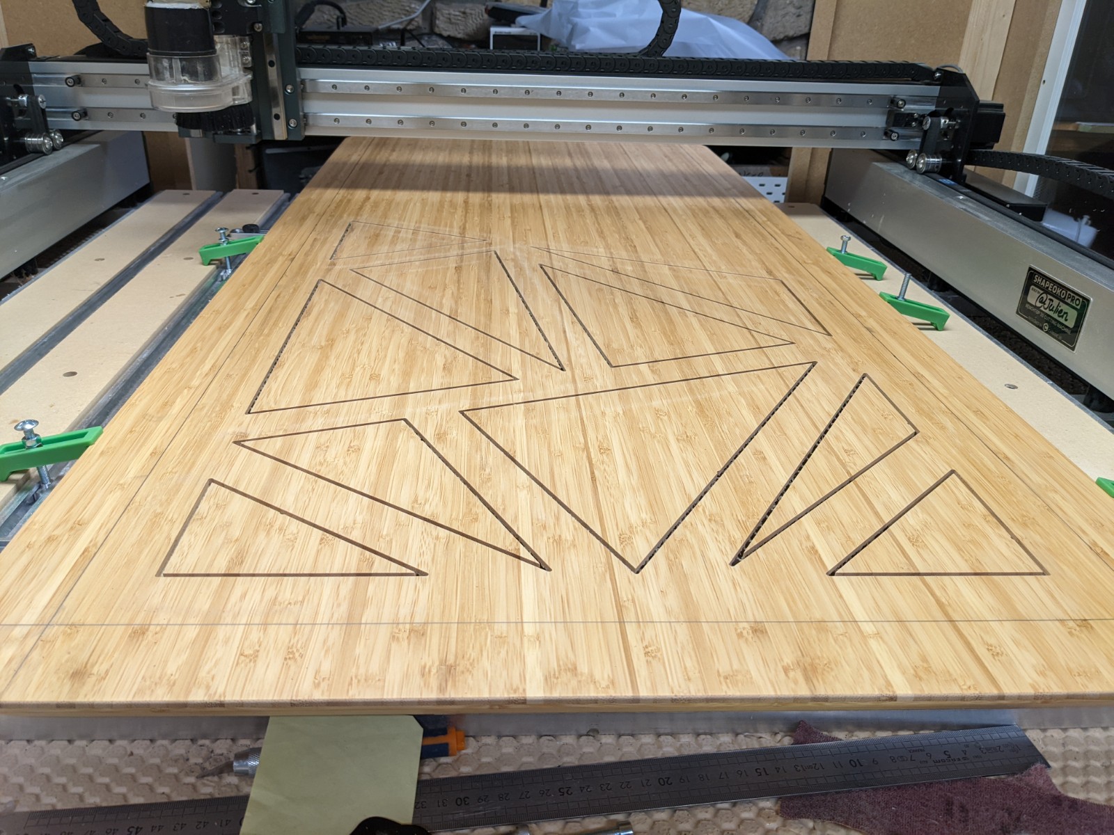
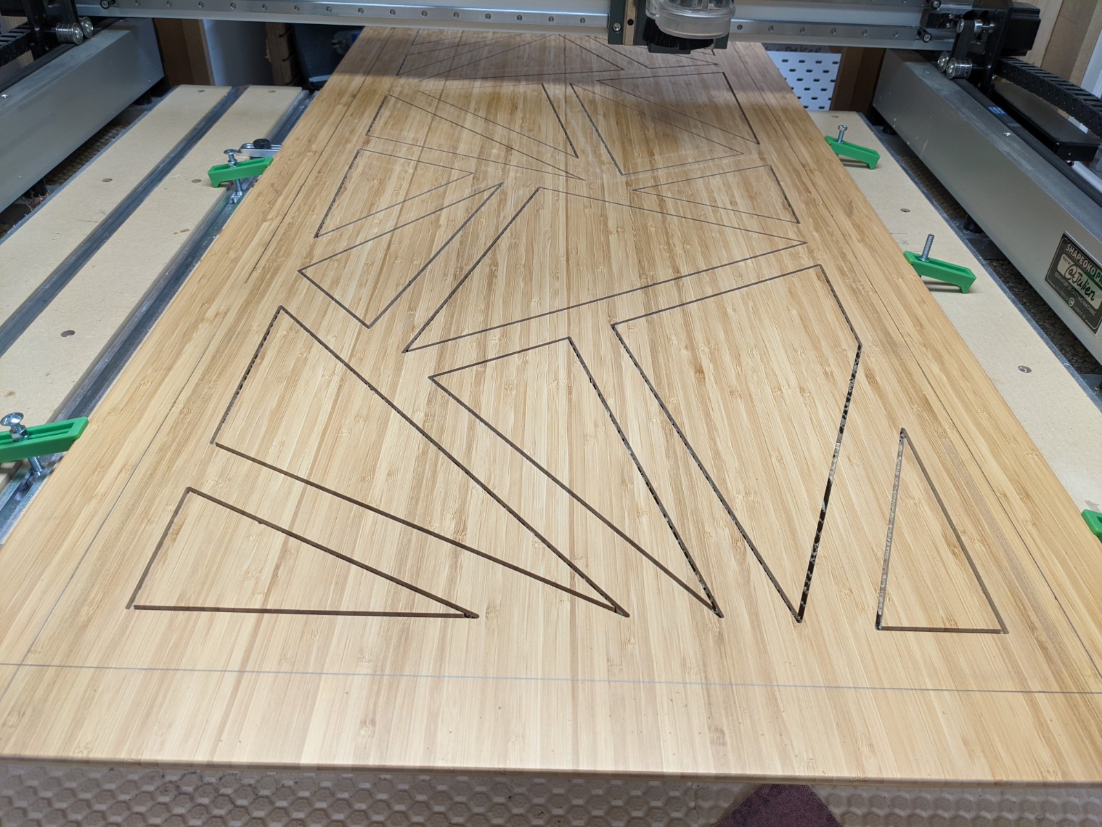
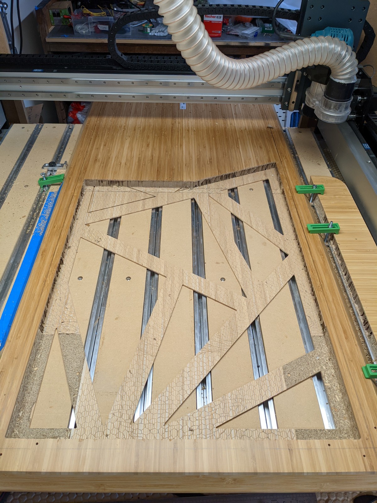
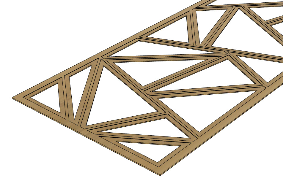
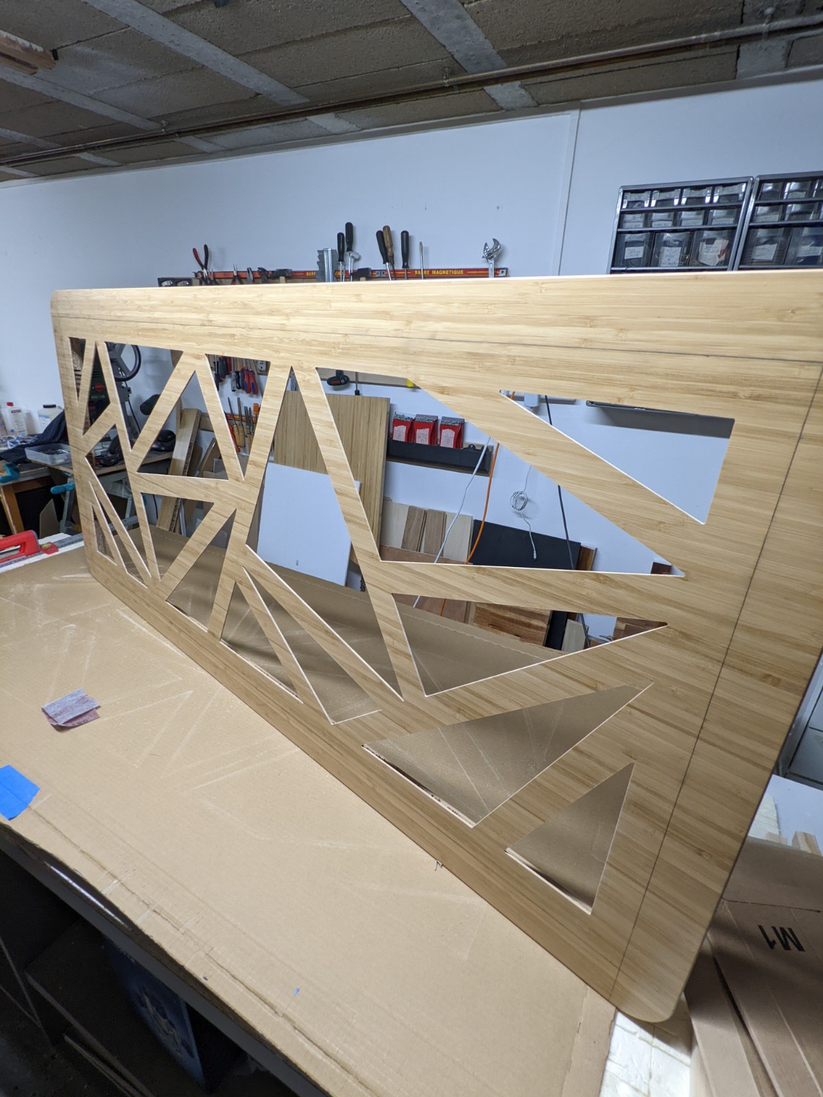
Prototype #2 started with carving half the triangles on the top face,


Then rotating the piece 180° and carving the remaining triangles (look ma’, no tiling required!)

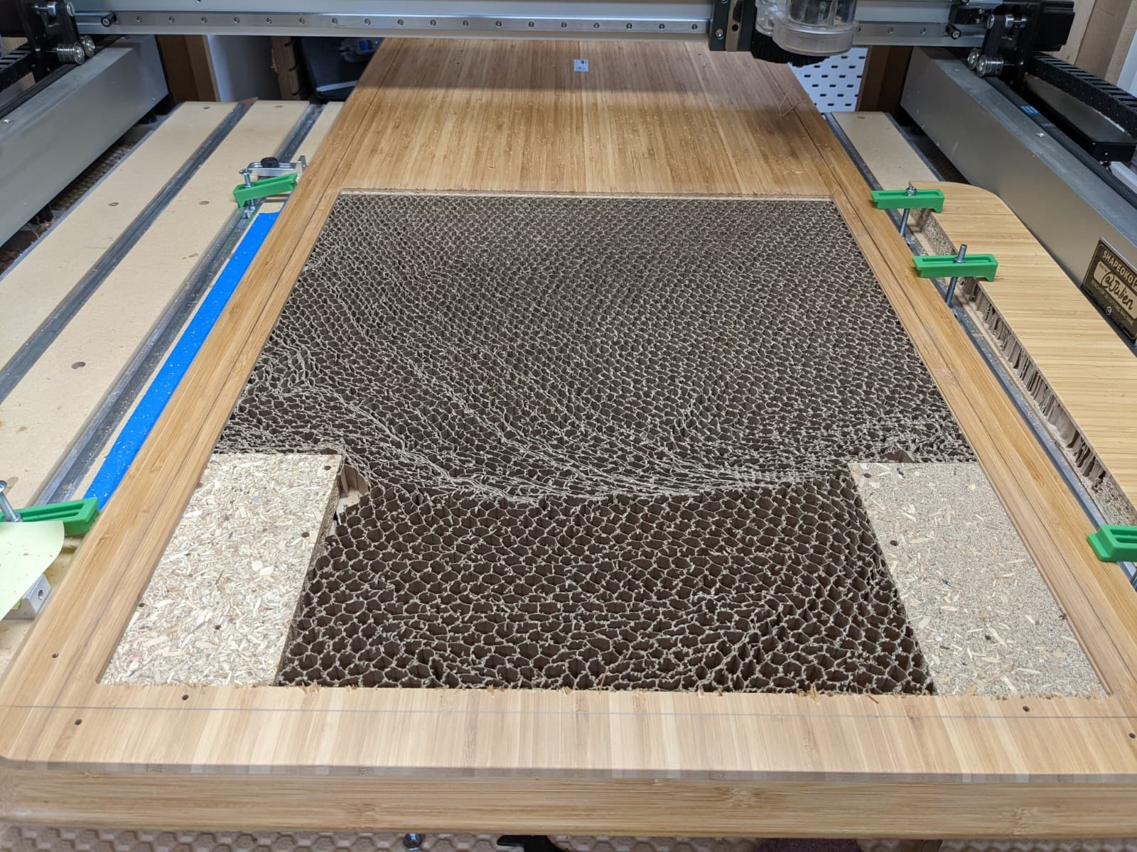
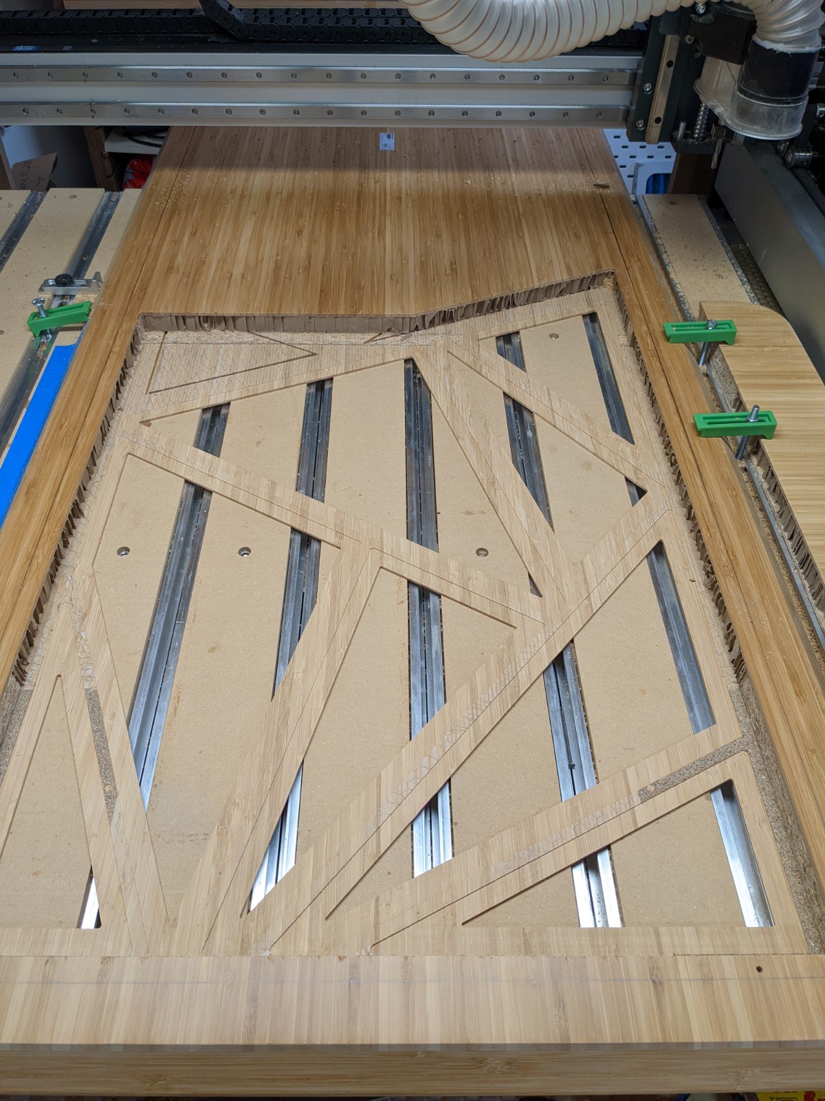
I flipped the tabletop to open up its back face, again one half of the panel at a time,

which after milling away the corners and removing the paper honeycomb structure manually exposed the back of the triangles:

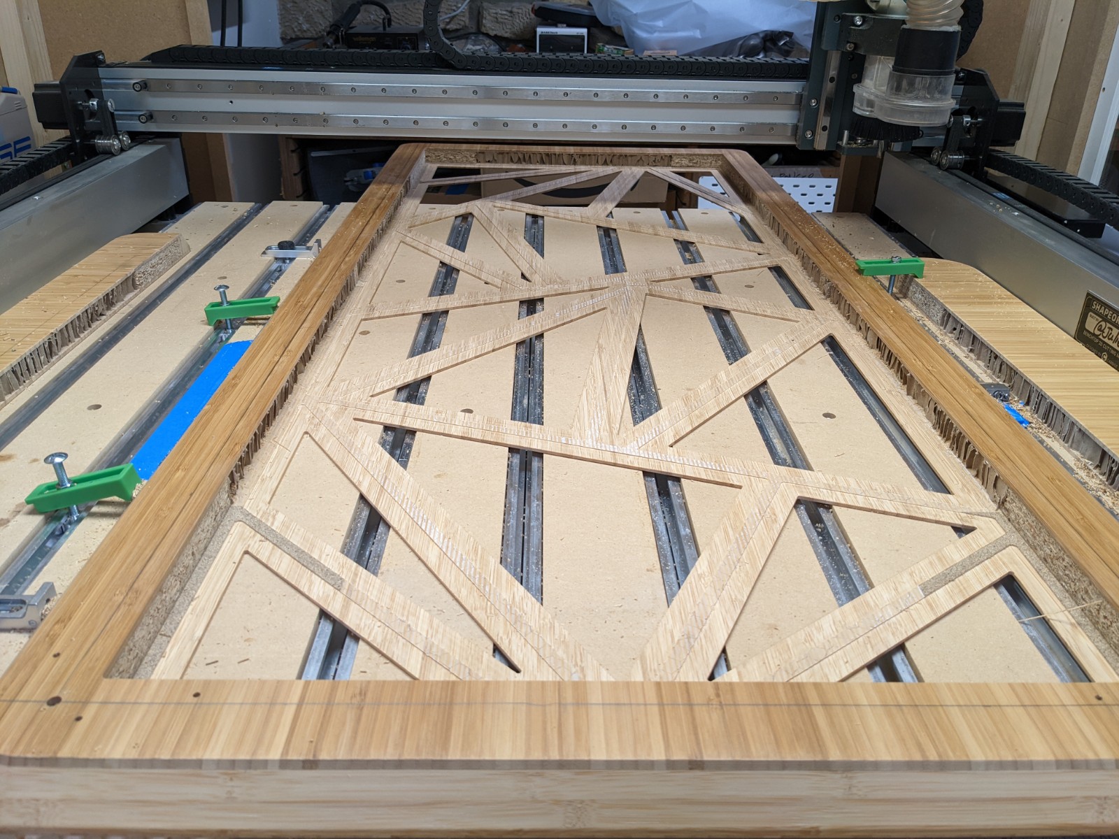
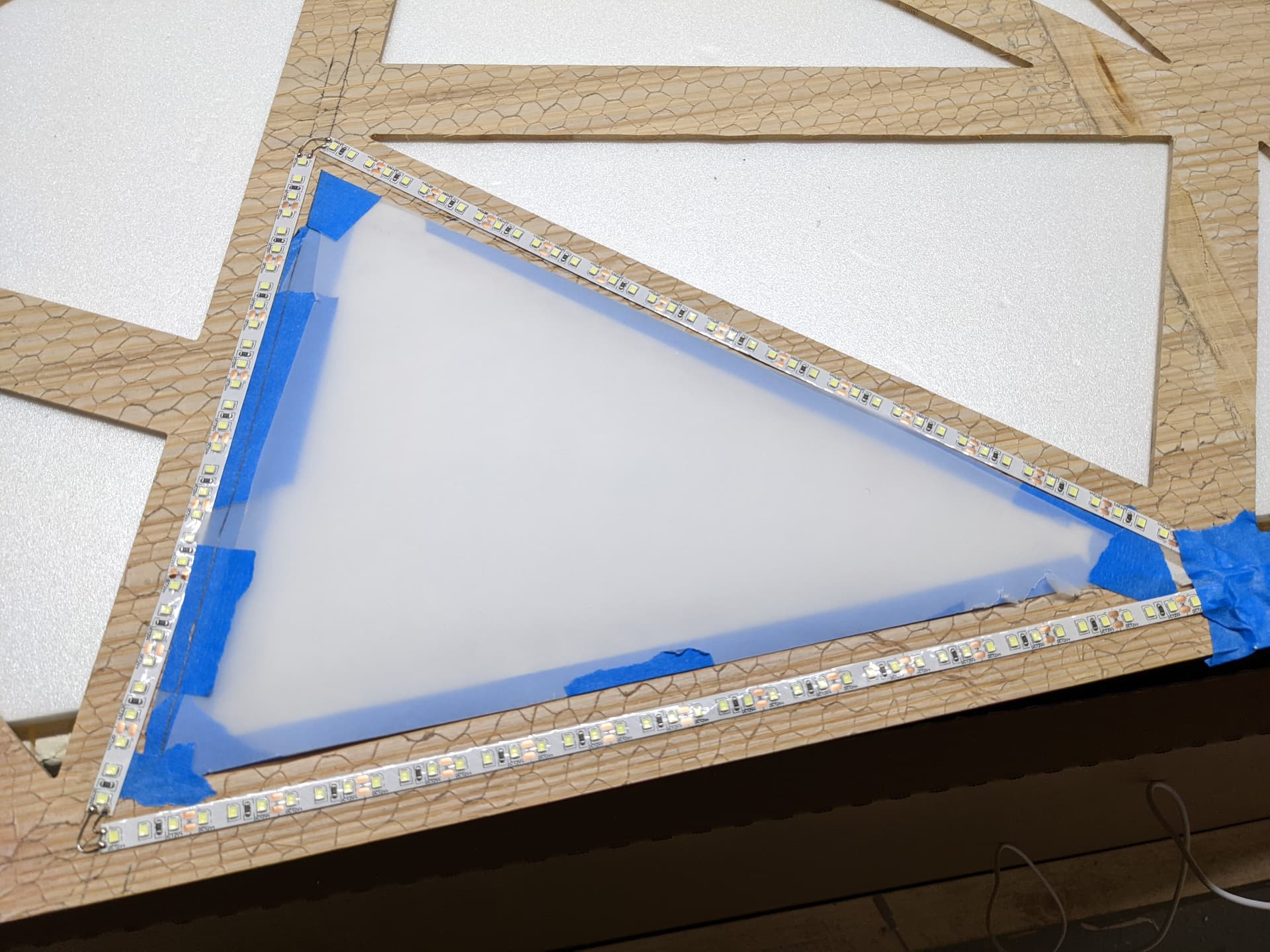
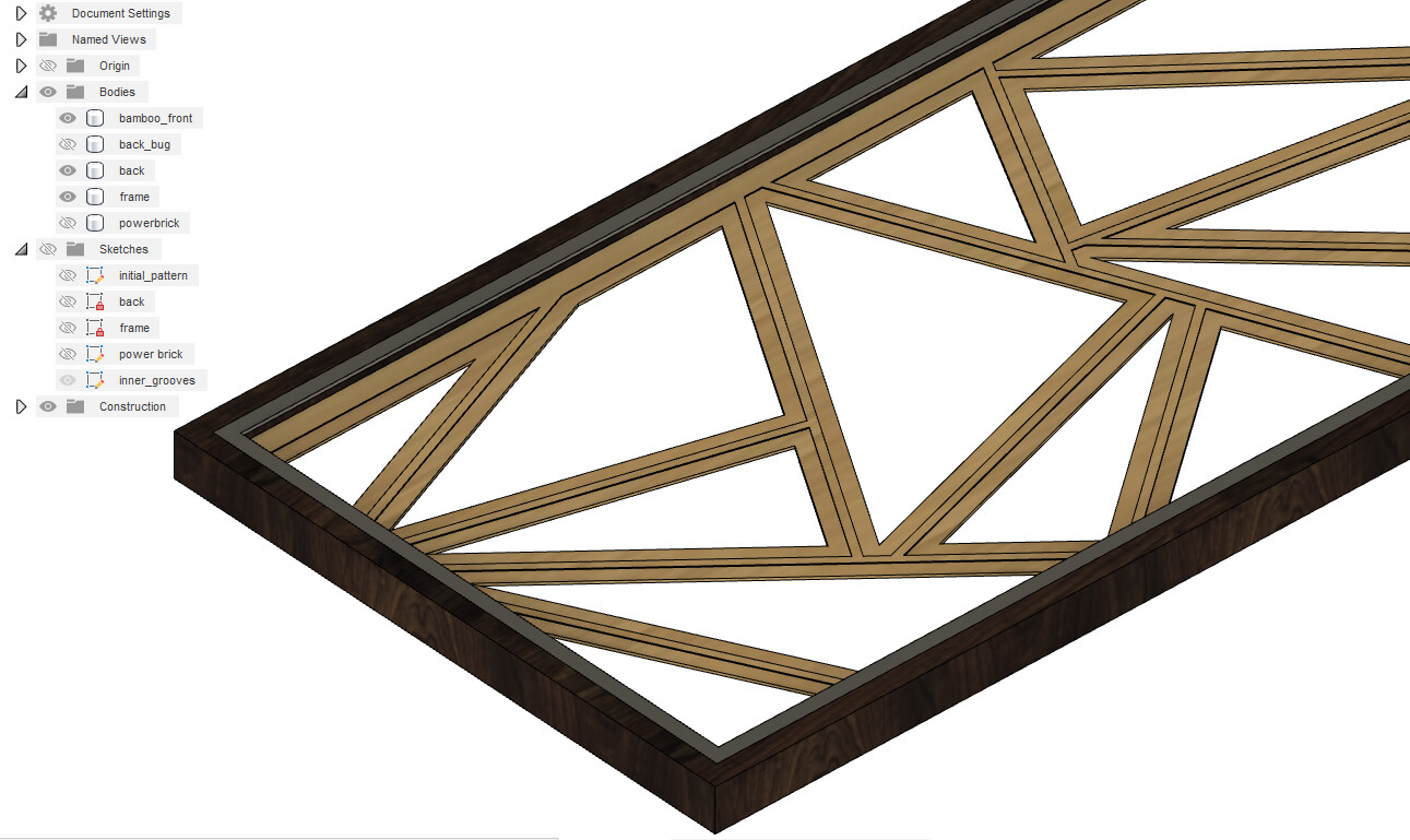
Then it was time to mill the triangle pockets (leaving “tracks” just wide enough to accomodate the width of the LED strips)

Zeroing off stock bottom worked great as usual. There was only 3.6mm of material left at the bottom, and I had no “internal” workholding solution at this point, so I just…used a downcut endmill, which naturally pushes the stock towards the wasteboard, and it worked like a charm:

Then I rotated the piece (again) and milled the other side:

At this point the thing is VERY lightweight, but still rigid enough for what I’ll do with it.

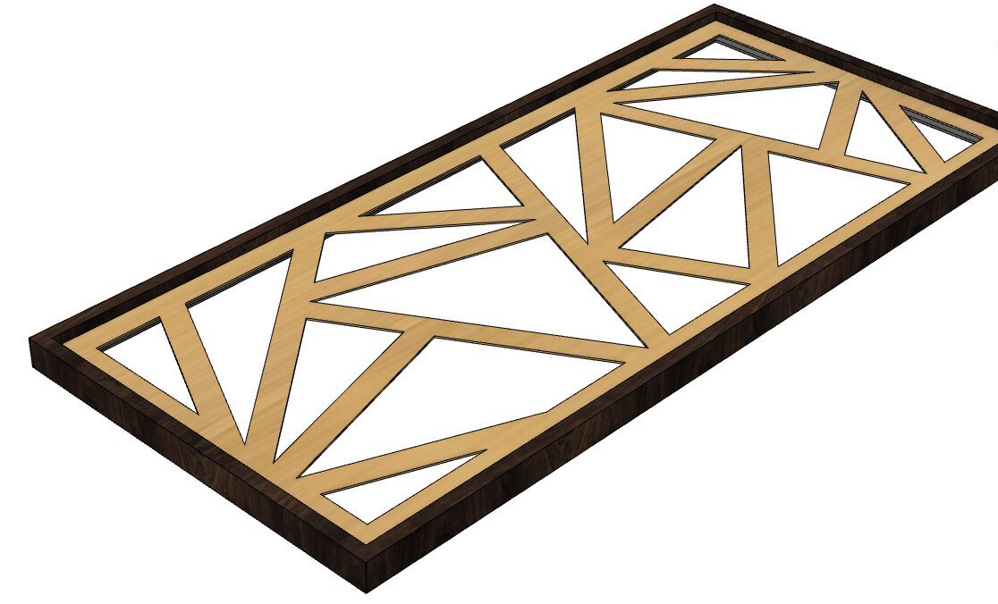
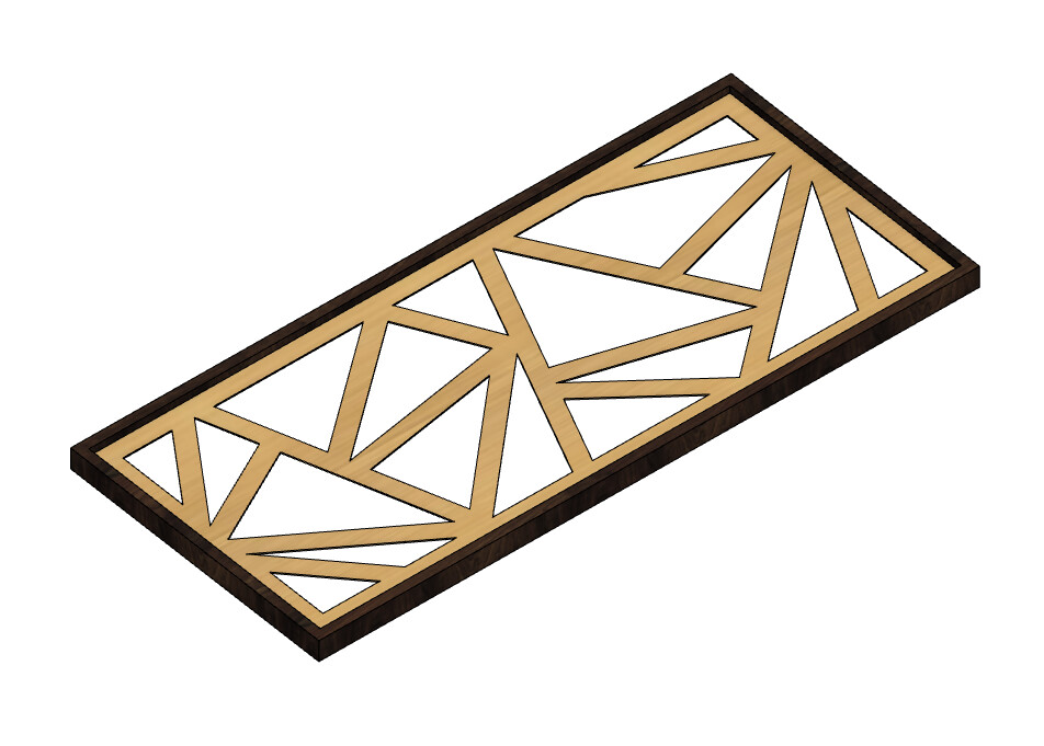
The pencil lines around the triangles is where I will eventually cut the piece using my track saw, to attach the frames, to have it look like so:

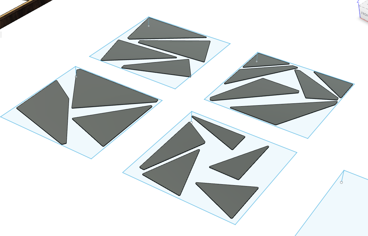
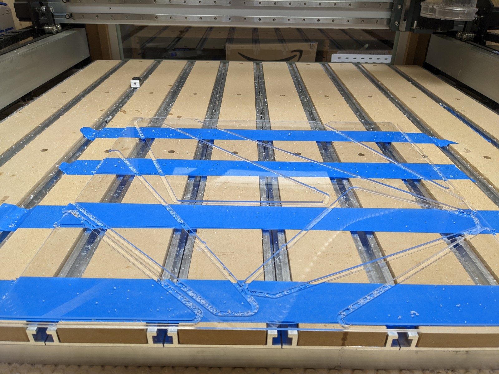
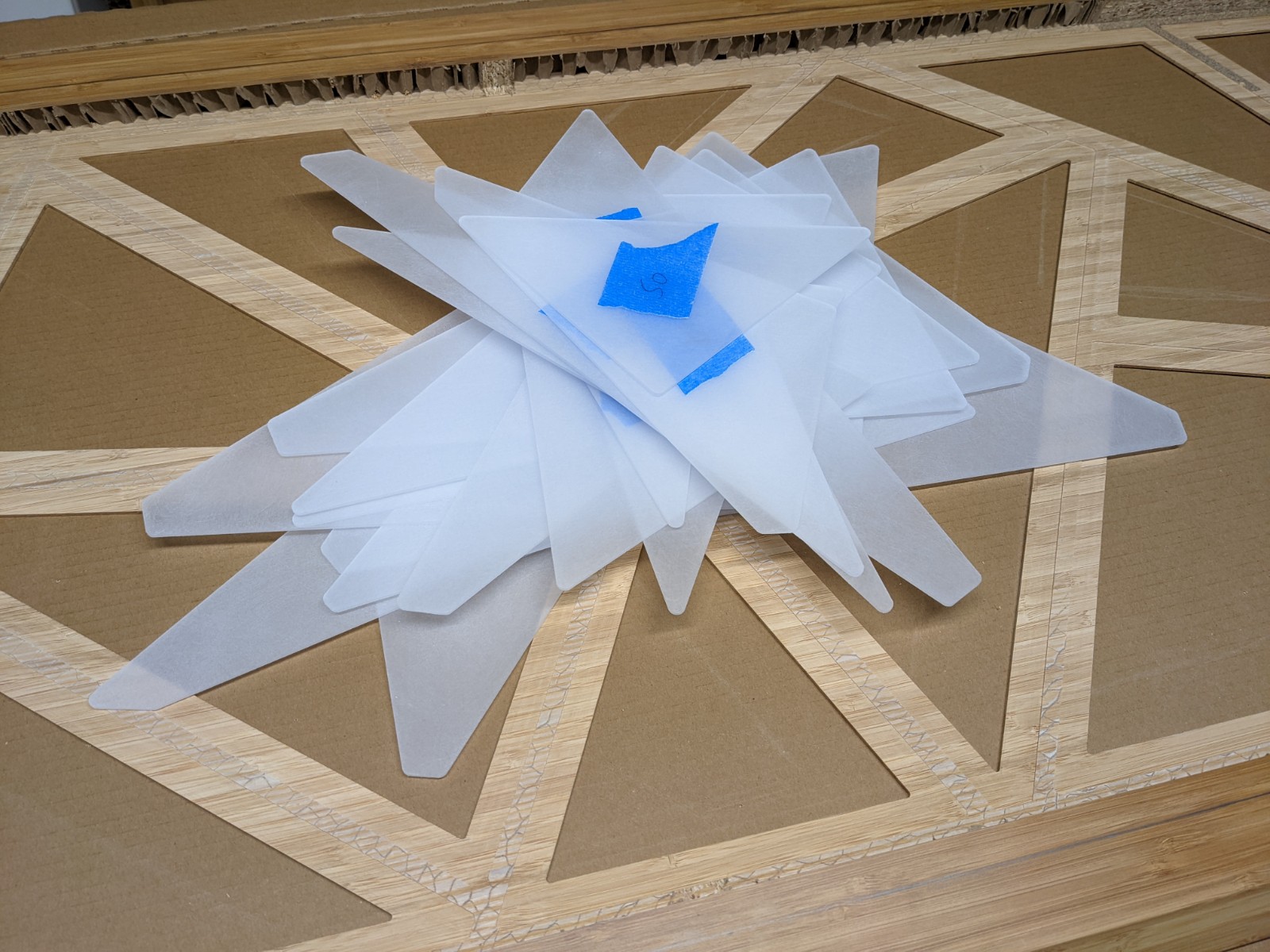
Then it was time to cut the acrylic backing/support for each triangle pocket,

I used 2.5mm acrylic, and my favorite single flute Amana cutter,

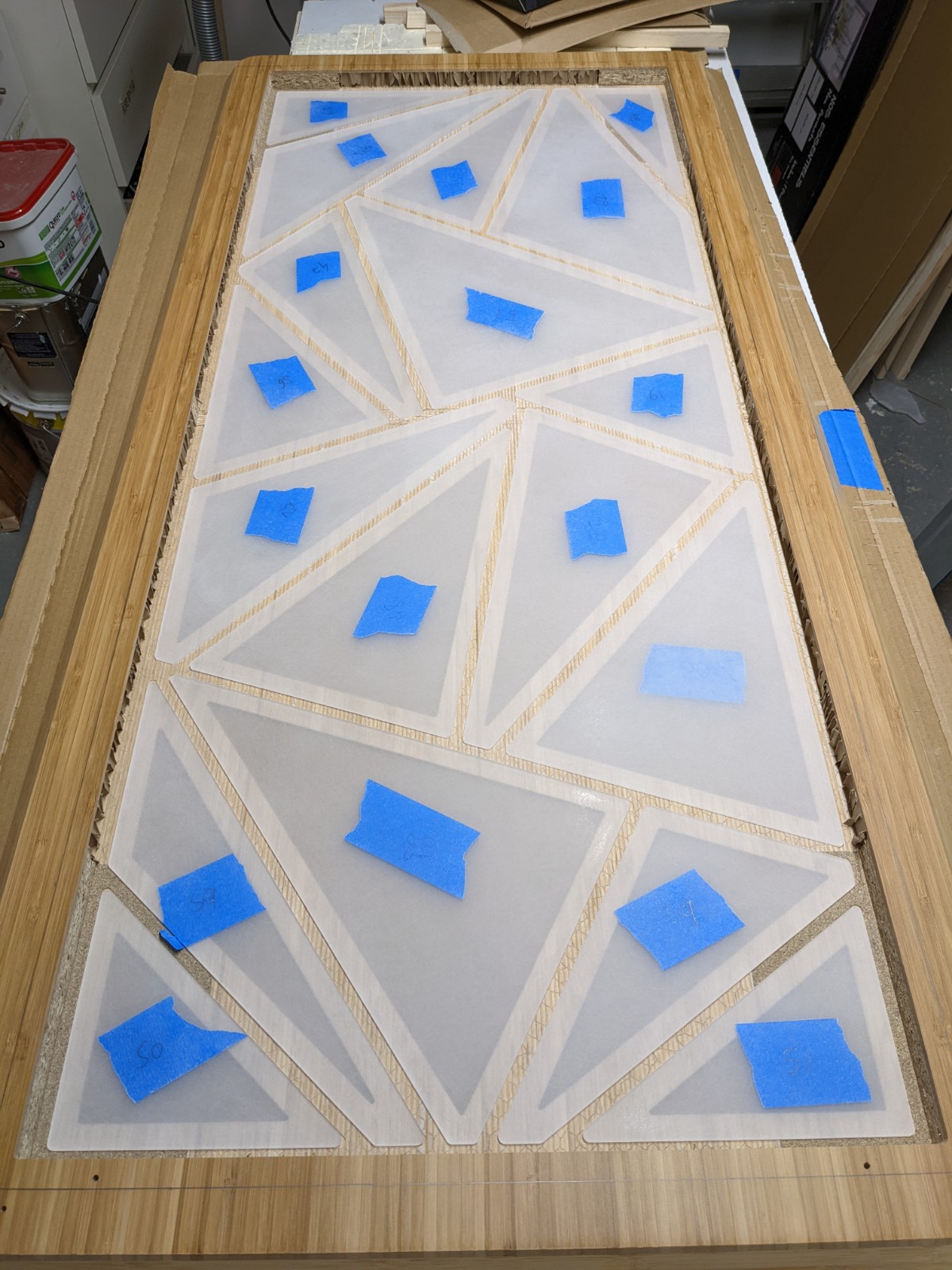
I sanded all the parts on both faces (phew…) and ended up with a stack of pieces,

which found their place in the pockets:

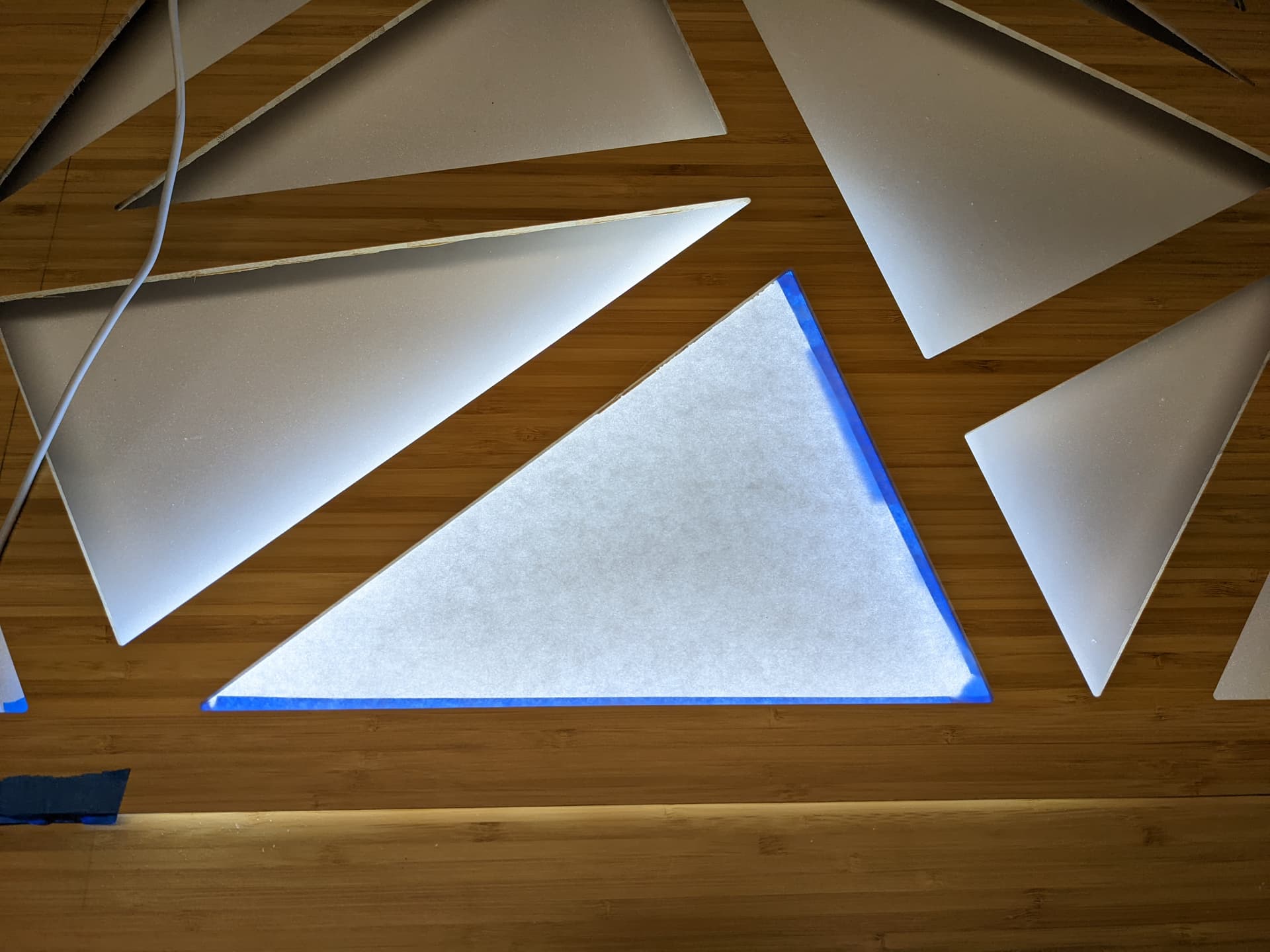
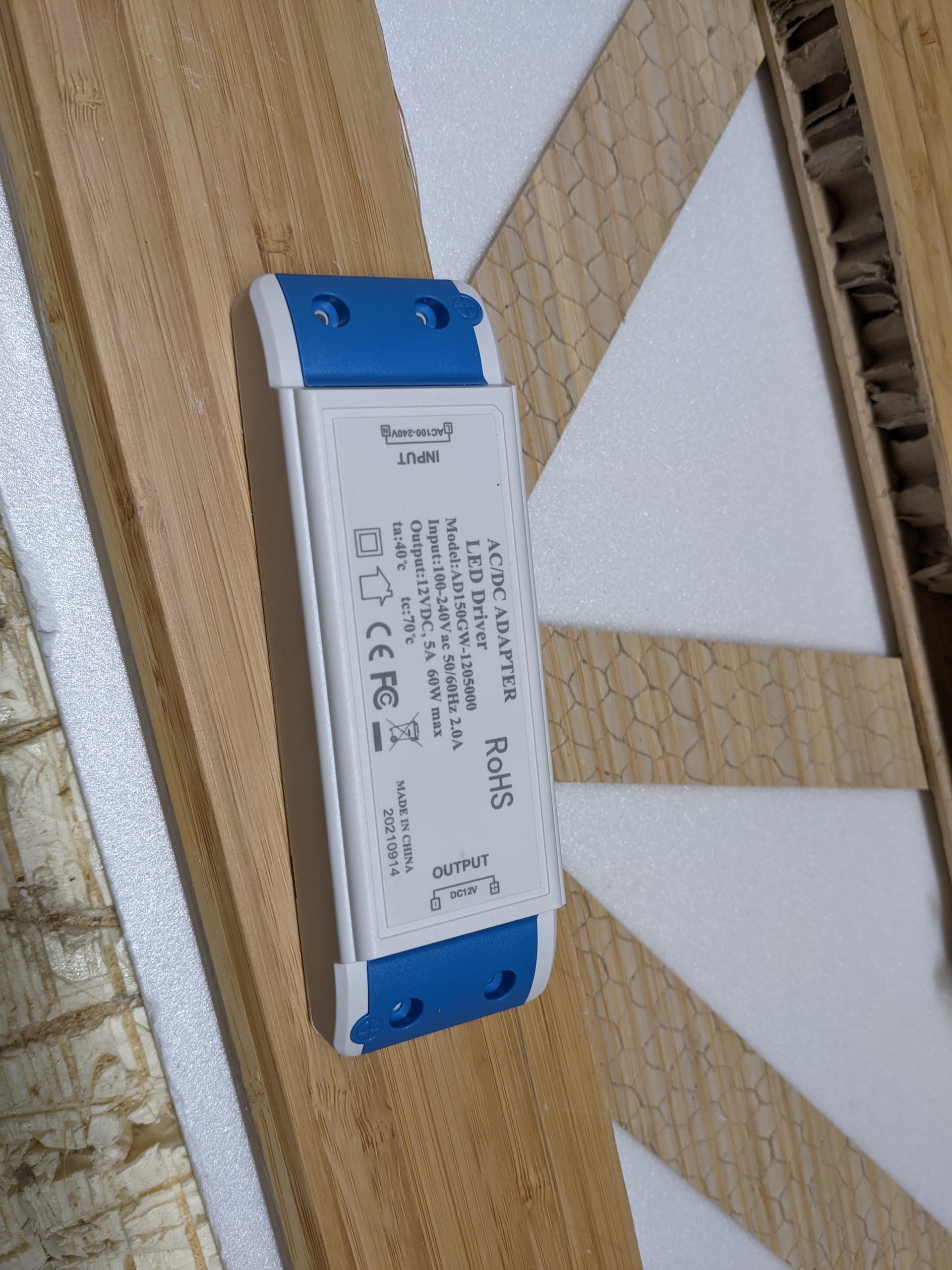
And this where I am right now. Next step: install the LED strips in-between (and around) the triangles. Then solder connections between all of the LED strips (which should be less than fun…).

And since I’m starting to worry that the triangles may look a little flat/uninteresting, I’m starting to think of carving triangles again using a translucent material to do a lithophane, using a subtle image/pattern that would spread across the whole piece. We’ll see!

11 Likes