Reprap is where mine came from -> https://reprapworld.com/products/mechanical/timing_belts/gt2x9_mm_kevlar_reinforced_timing_belt_per_meter/
Hey folks, thanks for being patient as I get this done.
I did not pursue the cyclic testing for now as I was not sure whether the failures in the field were due to tensile loadings or from stress of rotating around the pulley. If it’s the former, I can test it simply, if it’s the latter, I don’t have a good way to test that.
I did run the tensile loading measurements and wanted to recap what @AlexN found.
Alex’s measurements were:
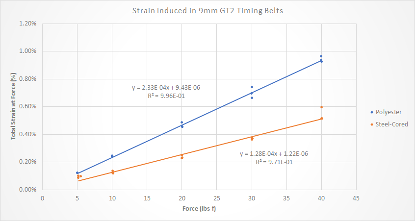
9mm stock polyester belt w/ 38lbs-f = 0.58% strain
9mm steel-cored belt w/ 38lbs-f = 0.30% strain
Equipment
I used an MTS Sintech universal testing machine (http://www.mts.com/en/products/producttype/test-systems/load-frames-uniaxial/universal/electromechanical/index.htm)
Procedure
I loaded the belt into the grips of the machine, ensuring 150mm of distance between the grips. I then loaded the belts with varying amounts of force from 5-40lbs (at 50lbs-f the belts started slipping from the grips).
Results
My results show higher strain values than what Alex measured.
For comparison:

The full data is below. So while my values are higher than Alex’s, the trends are the same. He measures the steel-cored belts at 52% stiffer while I measured 55% stiffer. We can chalk that up to experimental error.
Great data, thank you! My measurements were not very precise - I was marking the stretch with pencil lead about the same width as the stretch and doing my best to eyeball it - so I’m not surprised we differ, but have a similar trend.
The amount of stretch was definitely a surprise for me. In hindsight, it seems obvious that the belts will stretch, but general consensus on the forums seemed to be that the V-wheels, frame, end mill deflection, etc. were more of a problem.
I’m building a new CNC from scratch (for fun… nothing against the very nice SO3), and switched the design from belt drive to ball screw due to belt stretch. Before this, I had assumed belt drive (with steel belts) plus linear rails would get me the majority of the way there.
Before this, I had assumed belt drive (with steel belts) plus linear rails would get me the majority of the way there.
All depends on where you are trying to get. While I have only be running linear rails + belt drive for a little while, I have been very happy with the results. However my demands and criteria for my CNC needs are probably not as high as yours, especially with the cut parameters you mentioned at the beginning ![]() .
.
Would be interesting to see how kevlar belts stack up. From my limited research it sounds like it’s elongation characteristics could appear to be higher lower better than steel or glass fiber but I couldn’t find actual numbers - let alone in a “timing belts” application.
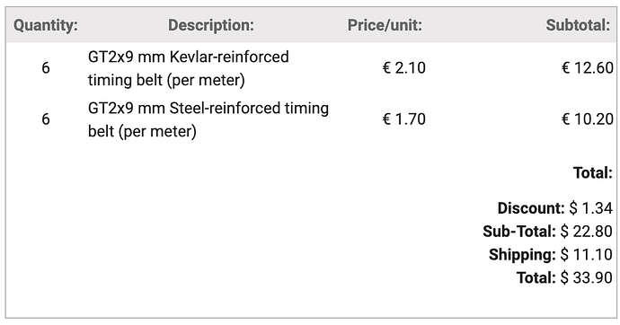
I checked the other thread about the steel belt breaking and then clicked on this link to get some kevlar belts, but the price seemed higher than what was in the other thread… Did you pay ~$6.50/meter (x10 meters) for yours with $11 shipping (so ~$76)?
Also, I still really dislike the threads close after one month… I still had relevant info to add to the other thread…
Order from 01/07/2020; shipping to Colorado, USA:
Looks like the price has gone up, also $USD to €EUR has gone up too.
If you want to continue a thread, just flag it and we’ll see if it should be re opened.
Thanks for letting me know, I ended up getting it anyways even though the price is about 3 times higher than 2 months ago because, unfortunately, my ‘need’ for the belting is about 15 times higher than 2 months ago so… I wonder how much of the increase is due to COVID-19.
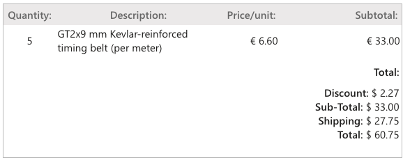
The shipping was the cheapest available to Cedar Rapids IA…
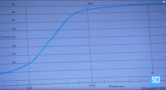
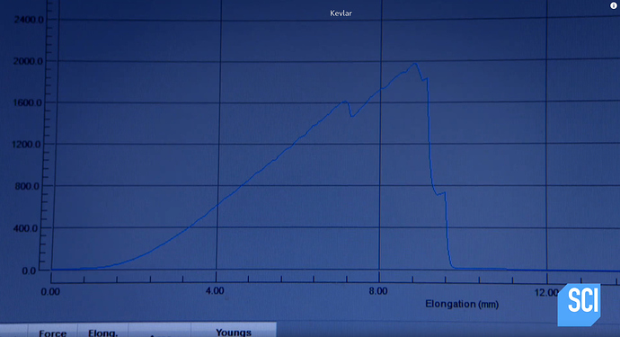
This is the best I have found for comparison
Of course this is just pure steel vs kevlar, the timing belts we’ve sourced will have additional variables (quality of materials and manufacturing, quantity/weight of steel vs kevlar, etc.)
Hopefully see some similar results though ![]()
Thank to Dan for sending me the Kevlar belts, I was able to get this done and analyzed.
Equipment
I used that same equipment as before. See my previous post above.
Procedure
I loaded the belt into the grips of the machine, ensuring 150mm of distance between the grips. I then loaded the belts with varying amounts of force from 5-40lbs.
Results
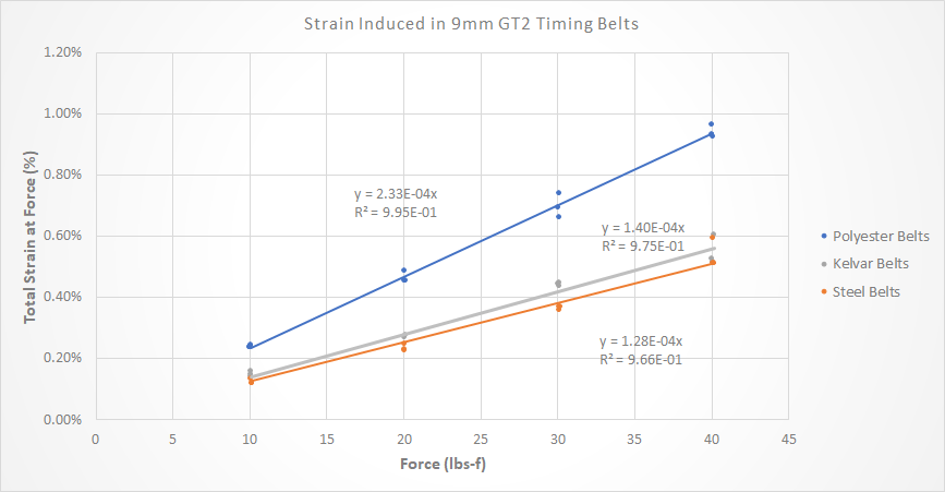
The Kevlar belts are potentially not as resistant to stretch as the steel belts but they are very close. I can’t say for certain that they are anything less than slightly stretchier than the steel because the statistical differences are small.
For comparison:

To put this in perspective, this is a difference of 2.45mm of stretch in the steel-cored belts and 2.65mm of stretch in the Kevlar-cored belts at 38 lbs-f. Realistically, we mill materials like wood and aluminum with radial forces closer to 10 lbs-f (@gmack can chime in here), the difference between the two are about 0.15mm of stretch with a 500m belt.
The charts and trendlines I used are below. I changed the graph from the prior one because I realized the data at 5 lbs is noisy due to the machine reaching it so quickly versus the higher loadings. I also forced the linear regressions’ intercepts at zero since at zero stress, there should be zero strain.
Steel belt stretches 2.45mm over 150mm at 38 lbf — 2.45/150/38lbf *1000mm/m = 0.430mm/m/lbf
Kevlar belt stretches 2.65mm over 150mm at 38 lbf — 2.65/150/38lbf *1000mm/m = 0.465mm/m/lbf

@The_real_janderson Can you switch your axis on the plot so we can get Youngs from your regression line? Since you used a standard gauge length it would be easy to directly compare stiffness!
Never mind… I need to learn to read, @gmack did it. My bad  Still though it would be cool to see it, if time permits !
Is 0.035mm/m/lbf a BIG difference or does that mean there isn’t significant difference?
It’s only about 8% of the overall stretch - not very significant!
It doesn’t seem very significant to me. I read that as steel and kevlar being interchangeable in terms of stretch.
There’s other differences worth considering: cost, availability, and durability (is one more prone to snapping, fraying over time, or permanently deforming?). I don’t know the answers to those.
Anxious to see @Microwave_Monkey’s results with Gates GT2 and GT3 belts!
Unfortunately, it might be a hot minute. Shipping dates keep getting pushed back on all my recent online orders. If all goes well, I’ll be able to run some tests and post a couple pictures or a video of the test itself here in a month or so, at best.
I should note they are knock off gt2 belts from some random factory in china.
The issue with trying to turn what I measured into Young’s modulus is that the timing belts are non-standard geometries. In standard tensile and elongation measurements, you have to measure the thickness of your sample because the stress is dependent on the cross sectional area of the sample. Since these samples don’t have a constant thickness, the only thing I could do is estimate one and then the samples would only be accurate compared to one another - you can’t compare it to actual, properly measured thickness samples.
tl;dr changing the graph to “Young’s modulus” wouldn’t tell you anything other than what you already see.
My fault, I’m used to pulling stress strain off of an Instron. I need to learn to read the axis on a graph😳. I thought you used a constant minimum cross section and calculated stress. Didn’t notice till after the post.
Granted you aren’t dealing with a material that has a typical stress strain curve, it has elastic properties, a non constant cross section, technically it’s a composite… so I agree the comparison to a standard material is a stretch(pun intended,) and likely the very reason you had to force a linear fit. So I suppose it would be more out of pure curiosity than anything else. You’re right though, stress/strain vs. force/strain would look identical, as you would have approximately the same minimum cross section for all samples. Only thing you would get by switching axis and expressing it as mm/mm instead of % is the same thing @gmac has, so no point. 
