Best approach for cabinet door panel

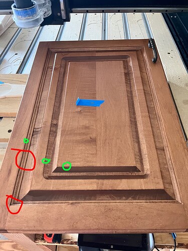
2nd paying job on my Pro 5, recreating this cabinet door.

The customer has been in the house for 40 years + , the kitchen has a full wall of these doors and doesn’t want to replace so they need the new matching doors.

This existing is above the refrigerator which is being replaced by a taller zero freezer so they’re loosing half the height , so the two repros right and left need to be in landscape orientation.

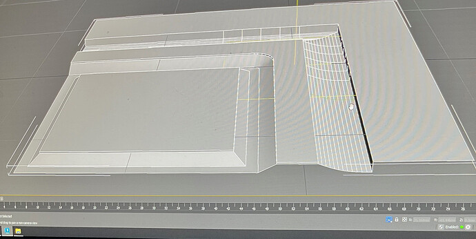
Using my calipers I carefully measured and made the model in 3D max. I’m doing a 3D scan of it as well to check against my model so I have the profile dead on.

Here’s where I’m not sure how to execute - use the model or import the profile as convert to tool path?

I haven’t found any cnc end mills with these angles so I’m thinking the best way would be simply import the model into Carbide Create Pro.

(off to work, Ill get the trial later tonight)

However easy enough would also be to just import the line profile. Does CC Pro have a function like vectric where you can define that imported profile as a tool path?

(Saw a Vectric video on YT doing this same thing very similar door)

The contractor is supplying the glued up 2x2 maple stock for the two 18x20 doors. Not enough to make the frame a separate one long piece to cut to size so its one milled piece. His cabinet guy will match the stain.

(I made him aware to tell the customer about the direction of the wood grain, it wont alternate with the frame)

Either method, model or imported profile —

What end mills?

I need the outside corner to be sharp and there’s the little trim profile - in red.

If I can find an end mill matching that little trim profile (red) that’ll take care of the sharp edge correct?

You can see the 1.5mm edges in green.

Assuming I cant find trim bits to ride those profiles, then my whole ball game will be 3D roughing / rest milling w/ CC Pro?

1/16th or 1/32 for the edges and a ball nose for the rest?

Not sure about step overs too, but Im sure Ill do sanding work

Thanks for putting up with my long post

If you’re going to cut this as a whole 3D model, I would consider doing in a software that looks at the model as an actual solid body / parasolid / et.al. Importing it in to CC will lose some detail. Cutting it in CC will be problematic as you only have 1 direction for a 3D finish cut. You would want to separate it into sections following the contour lines as opposed to across them.

That being said, I would consider just ‘shrinking’ the existing door by making 2 cuts & removing the middle section & joining the remaining sections together. If the bottom of the door is above the fridge, the joint may not be very noticeable.

Hey Todd, thanks for taking the time

I made the 3-D model in 3-D Max so it does it as a solid object.

I’m not really sure what you mean about a 3-D cutting one direction? How else would you do complex 3-D carvings?

I was on the impression with carbide create pro you can just import your models. I don’t see anywhere in the documentation that you lose detail.

And I’m seeing it done on YouTube in Vectric , where the guy did it in one piece, But he just drew his profile Instead of a 3-D model.

6 of 1, 1/2 a dozen of the other?

And cutting in half is a great idea, but they need it wider because of the zero freezer going in as much wider than the existing.

Ah, OK. I missed the “wider” part.

What I meant by cut direction… you only need to cut the depressions, not the entire part, right?
And you probably want all the cuts going parallel to the grooves, or perpendicular to the profile cross-section…

image

I wouldn’t call this “complex 3D” like a carving of an animal or nature scene, etc…
It is predictable prismatic shapes extruded/projected along a linear path. “Complex 2D” maybe?

STL is a faceted model that represents/approximates a solid model using flat triangular surfaces. The tolerance defines how many triangles, but there is always a tolerance. Whereas a real solid model defined by lines & arcs, or even B-curves (splines) extruded along a path is exact.
If I trace a linear toolpath across an STL shape, for example along the parallel cut directions I mentioned, The Z axis will change. Cutting parallel to an actual solid, the Z would remain the same.

The place I’ve seen it the most is text modelled into the STL -vs- text cut with a 2D boundary projected onto the 3D surface. The first has a jagged edge where the second has a nice clean edge.

Hope that helps. It made sense in my brain… :laughing:

1 Like

STL is a fixed faceted surface representation.
All points are predefined, so any sampling needed is based on the location on a finite triangle.

The idea is to have a geometric representation that uses curves and surfaces.
That way the fineness control is more flexible/accurate. A curve or surface can be sampled as needed.

It looks like 3DMax will export ACIS .sat file format.
I am not sure if the resulting file is the same mesh or has been post processed to curve/surface entities.

Late reply, long week of cutting beer tap handles so just now getting back to this.

Thanks for the help gents, but Im still a little unsure.

The contractor dropped off the 2 ft x 2ft maple blank and the measurements.

The doors need to be 22 w x 11 high.

“STL is a faceted model that represents/approximates a solid model using flat triangular surfaces. The tolerance defines how many triangles, but there is always a tolerance. Whereas a real solid model defined by lines & arcs, or even B-curves (splines) extruded along a path is exact.”

Copy that Todd. All to familiar with messy triangulated 3D models.

So if I understand, probably more accurate to just draw native lines instead of importing STL?

Today I am doing the 3D scan , then Ill import into 3D Max and redraw the profile.

Scroll to 13 minutes in.

Can I do this in Carbide Create Pro? I have the Vectric trial but you cant export. Money is tight so I cant buy that after seeing this vid so I’m hoping that CC Pro trial can do this and Ill buy that outright when I get paid for the doors.

If you will post a 2D profile drawing we will walk you through creating it in some fashion.

Note that you may want to review:

and also see:

Thank you kind sir, Ill do that shortly (1230 pm cst)