Since @Vince.Fab has joined the spindle club, I thought I’d share how I set up my BEST vfd to drive my spindle motor from the Carbide Motion Board (CMB).
I wanted to use the PWM output of the CMB to control the ON/OFF of my spindle as well as the RPM. Unfortunately, the BEST vfd I purchased only accepts a 0-10V control voltage and not 0-5v delivered by the PWM pin on the CMB. To get around this I purchased a module that converts the 0-5v PWM into a 0-10v signal. A link is here (order the Number 1 - 5vPWM to 0-10v):
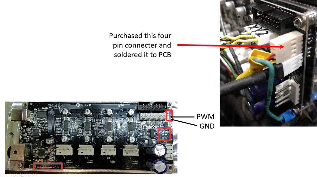
Connecting this PWM module is reasonably simple. I purchased a 4 pin connector from a local electronics store, and soldered it directly to the CMB PCB. Please refer to these instructions (scroll down to the pictures of the PCB’s and follow the PROCEDURE portion carefully
The important point here is to have a wire connected to the PWM terminal (in my case its the RED wire, and the GDN terminal - my case the black wire). You don’t need the connector I added.
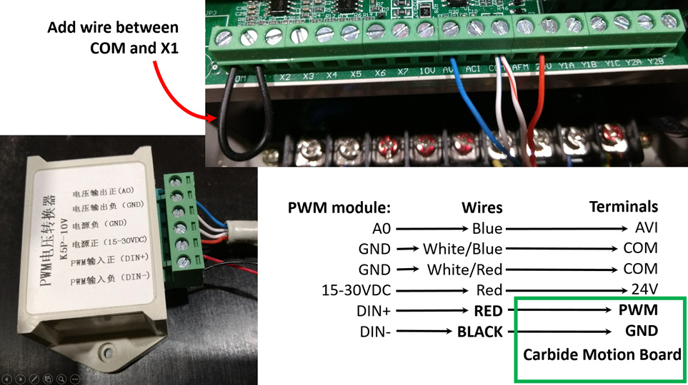
Next step is to connect the wires from the CMB to the PWM module and the BEST vfd. Just follow the picture below:
In addition to the wires between the CMB / PWM module / BEST vfd, you need to add a wire between the COM and X1 terminals on the BEST vfd.
You also need to connect your AC supply to the Live and Neutral terminals on the BEST vfd as well as the three wires to your spindle motor (U, V, W). If you are not experienced electrically - get someone appropriately qualified to make the AC / motor connections for you!
In the next post, I’ll continue with the BEST vfd setup…
With everything connected this way, and the parameters set, as soon as you run a g-code file your spindle should start up and rev up to the desired RPM.
I’ve banged this info together pretty quickly - so it might not be clear to all. If you have any specific questions, just let me know.
Awesome write up @3DGG. I don’t use the BEST VFD but wish I had a simple write up like this when I was setting mine up!
The only note I’d add for people new to the spindles, if the spindle is spinning the wrong way to swap any two wires (U,V,W) to the spindle to reverse the direction
Having spindle control for me was a huge improvement, being able to just click start and have it spin up and start cutting is awesome, as well as being able to dial in your speeds, with the option of having a spindle override (I don’t think Carbide Motion supports this - CNCjs does)
I also built in a 15 second ‘Spindle Delay’ into my sender (LinuxCNC) so that the job will pause for 15 seconds while the spindle runs up, otherwise it can start cutting before it’s up to speed. Obviously not everyone runs LinuxCNC, but this can be programmed into whichever Post Processor you’re using.
(Please test with an air cut before using as I’m away from machine and can’t test)
Add G4 P15.0 to your post processor or edit your Gcode and add at the start
G4, followed by the P, sets the delay. If a decimal point is not placed after P the number is in milliseconds. If you use a decimal point, as I did in the example, the delay is in seconds
edit - just found another option… Add ‘M0’ (zero) in the line after your M3 command in your post processor, this way you click ‘run’ to start and the program will actually pause as the spindle runs up, then when you are happy it’s at speed you click run again and the job will start