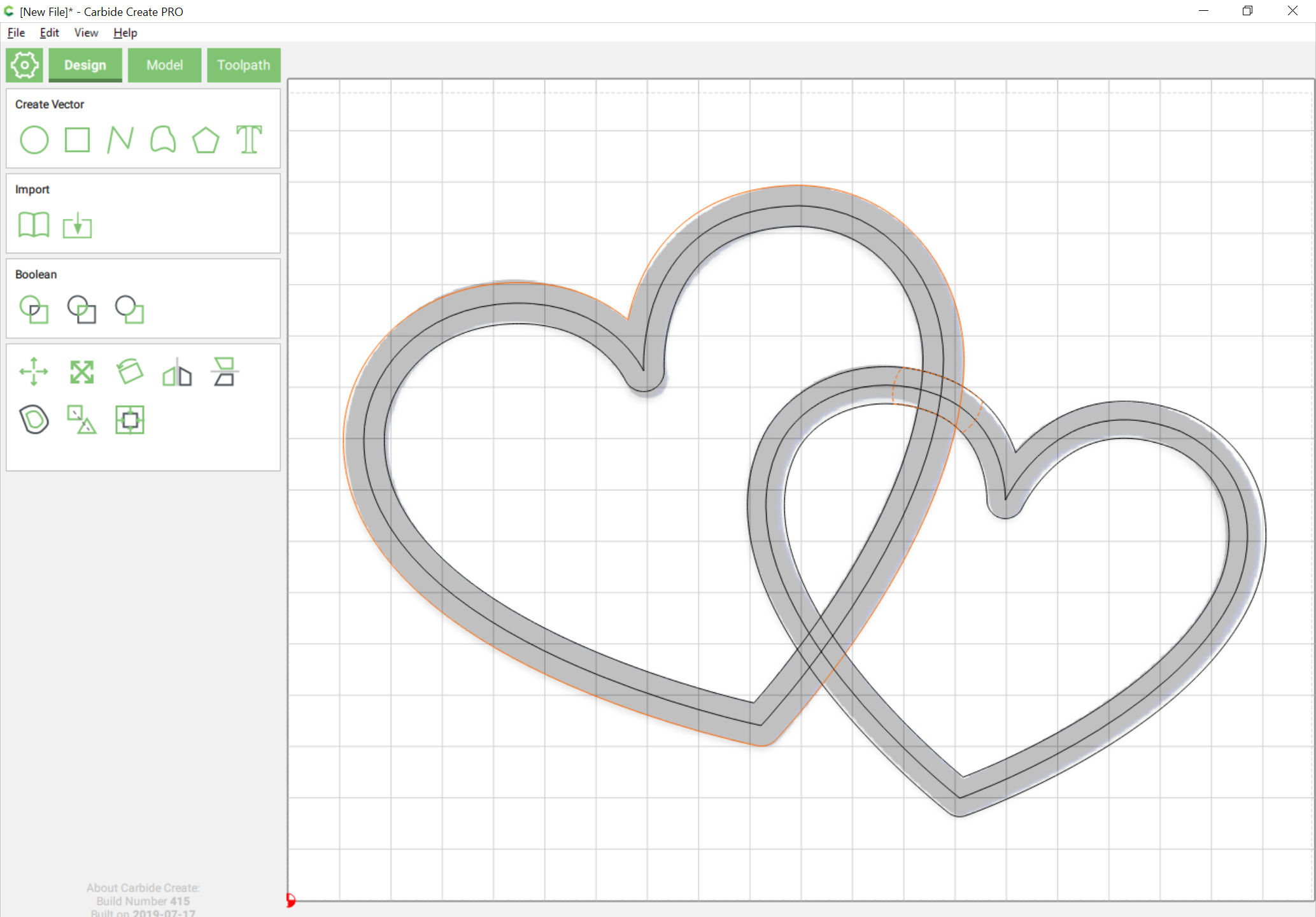
The Boolean subtract the intersection area from the larger heart:
resulting in:
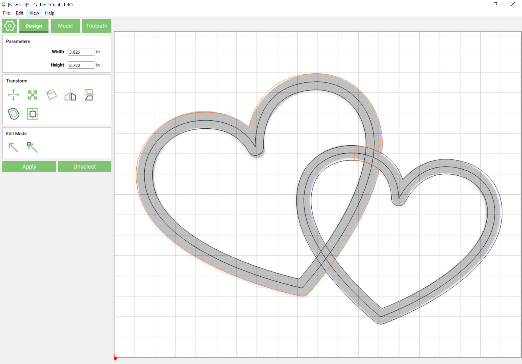
Then select the punched out heart and the inner heart:
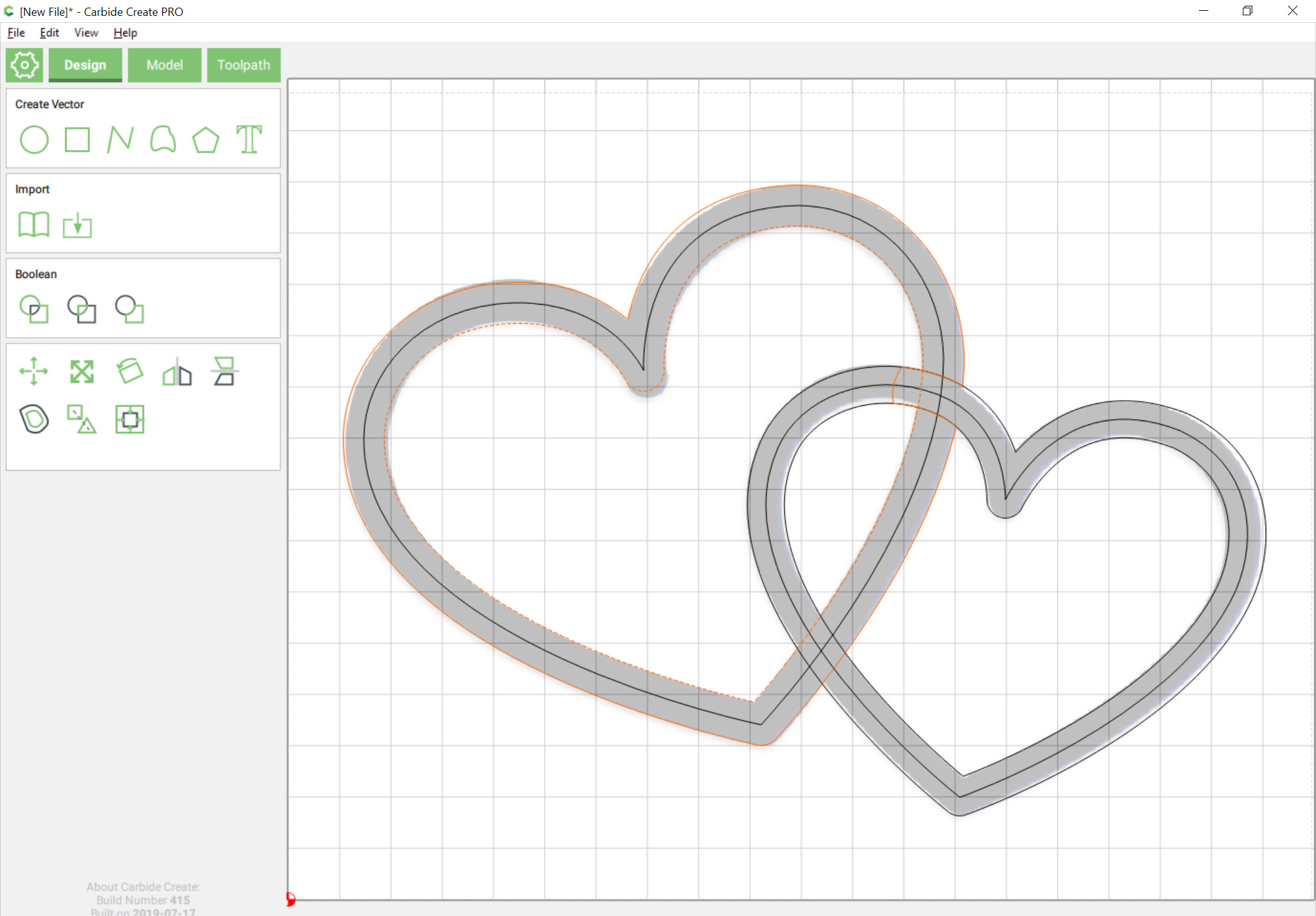
and do Boolean Subtract:
Repeat in opposite for the other intersection.
The Boolean subtract the intersection area from the larger heart:
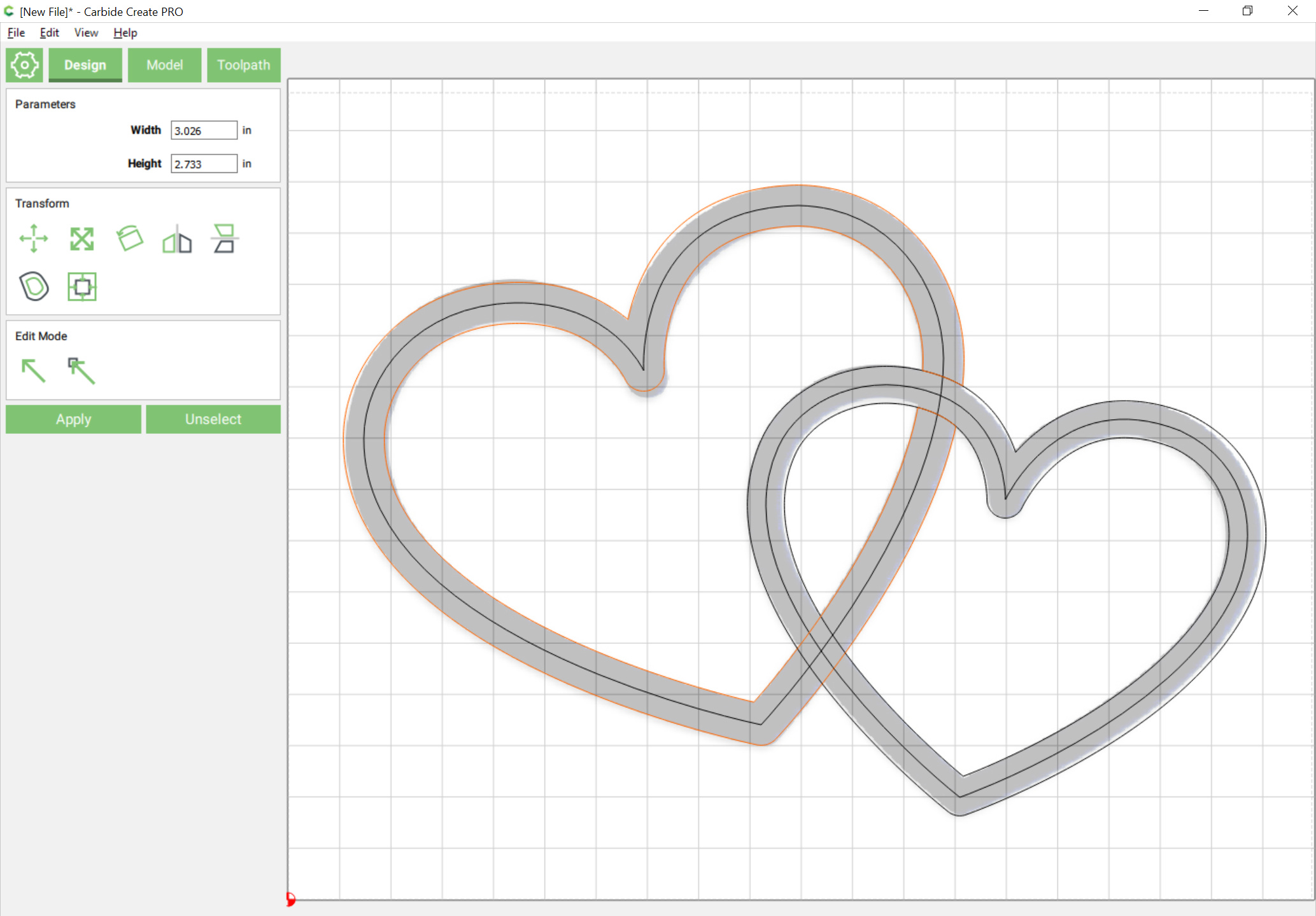
resulting in:
Then select the punched out heart and the inner heart:
and do Boolean Subtract:
Repeat in opposite for the other intersection.