Hi all - I got my Shapeoko some months ago and having the time of my life.
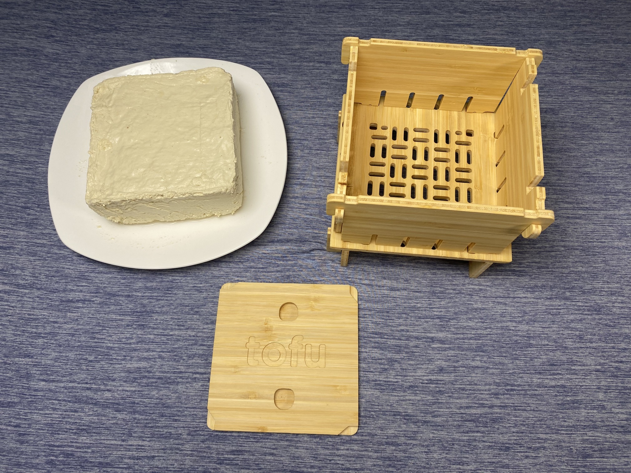
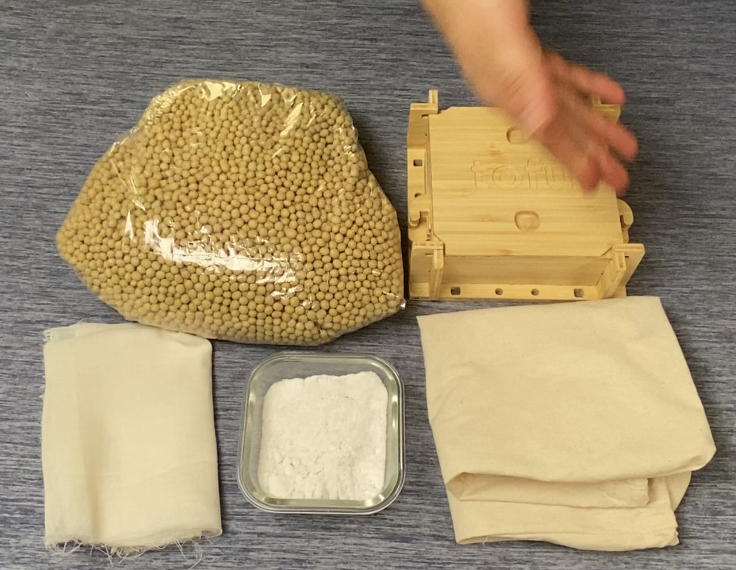
I’m running a small manufacturing of kits (see below) and one of the items is an intricate bamboo-plywood box created entirely on the Shapeoko, and being assembled with no glue or nails. Came out a beauty!
My task now is to get into manufacturing mode, and that’s where I am seeing some simple improvements that Carbide Create (and Motion) could use to make the software more production oriented. Mostly small items…
I have been a software developer for >25 years specializing in graphic automation, so this is perfectly aligned with what I do well.
I listed some bugs and requests below, feel free to comment. I also would be happy to join any beta program to help test.
Some of the bugs I found have to do with selecting objects, which is super important. Selecting the incorrect object before creating a toolpath could mean a ruined workpiece.
See below:
Bugs:
When trying to add to a selection with the shift key, if I shift-click and miss the object, everything gets deselected. The selection should remain the same.
Drag-select encompasses more than needed. Objects that are not inside the marquee selection are all included in the selection
Small objects can be literally impossible to select
Indication of objects hovered over should be more pronounced. Right now the line becomes a tiny bit darker but the difference is almost impossible to see.
Import SVG comes in at 75% of size it is in Illustrator
When importing SVG and then trying to move the objects imported, other objects sometimes get ‘selected’ by error and move as well.
Top buttons operation: If user is in Toolpath-mode, then click settings, click Ok to exit settings, the screen goes to Design mode instead of going back to toolpath mode.
Toolpath mode disregards grouped objects when selecting
Easy changes:
Shortcuts for group, ungroup: (Command-G, Shift-Command-G)
S = scale
R - rotate
Command +/- for zoom in/out
Needed features:
Lock/unlock objects
Layers in design-mode for easy hiding, locking
Redo capability
Suggestions:
Move Retract Height setting to specific tool path, or allow tool path to override retract height. This will be super-useful when starting with a toolpath for screws. The workpiece is not yet screwed to the spoil board in the middle and may be higher, requiring a higher retraction.
Better tab addition: Treat tabs like normal objects I can move and delete individually
A ‘hole’ tool in Design-mode would be great as right now I have no way of using the 1/4” bit to just bore a 1/4” hole.
Carbide Motion
Allow custom key-binding for Jog commands so that it is easier to program a separate keypad. Otherwise it’s a chore…
Higher contrast between enabled/disabled/default buttons. It is sometimes difficult to tell if buttons are available or not.
Pocket cuts leave a sliver of material in the middle. Needs a small overlap on first inner-loop.
Rough preview in Run screen. I want a small preview of the file for final verification.
Would be nice if we can have custom steps between toolpaths, such as ‘Pause’, ‘pause and raise spindle’, and add a custom message.
In Rapid-jogging, it would be great if I can click on the board-mockup and have the spindle rapid-jog to that position.
Regarding selection (Bug #2, above) …LightBurn uses a CAD technique that I find very helpful: Drawing a rectangle down from the top left means, “Select all objects that are completely contained within the rectangle and ignore those that aren’t”…whereas, drawing the rectangle from the bottom right upwards, means “Select any object that intersects with the rectangle, even if it’s not completely contained”. This is a really convenient feature that would be a big bene in your selection woes (bug #1, 2, and 3).
The 75% SVG is a known issue revolving around the assumed DPI being used (72 vs. 96) and the use of pixels to specify size. There’s a thread on this Here. In LightBurn, the developer there just implemented a “tolerance” for CC created SVGs to compensate for it.
On the suggestions:
I second all of the CC Recommendations.
For the CM Recommendations, the ones that resonate for me and I second a desire for are: 1, 4 (and my suggestions Here), and 6.
Thanks for the suggestion list. We’re probably close to starting another CC push in the near future so I’ll add this to the list of things to take a look at and we’ll see what’s a good fit.
Another request:
The toolpath zero can be placed at center, lower left, center-left, or upper-left. Can you add bottom-center, or better yet, arbitrary zero?
Also, the Carbide Create workspace coordinates are always (0, 0) at lower-left corner. Can the workspace coords be made to match the toolpath coordinates? Is there some reason why this would be a bad idea?
While you can move the design around to achieve this, when moved you won’t get a 3D preview of the stock unless you use center and it is smaller than half the working area of an XXL along both axes.
Yes, this is what I have been doing, but then I have to mentally offset my coordinates. This becomes tiresome and error-prone if I want to create an array. Also, Carbide Create won’t let me use a workspace larger than my XL can handle, so if I put the toolpath zero at workspace center (with my design entirely above the centerline) I am really limiting the size of my design.
We try to keep it simple to reduce confusion, that’s the only reason at this point
CC will not limit the size or location of the work piece at all, the table is shown just to be a reference to show you some “real” scale for the parts. You can put your design anywhere relative to the zero or the table in CC and it’ll generate a toolpath for you.
Yes, you are correct – sorry about that. But I can’t specify a stock size larger than the working area of my machine, so if my design dimensions exceed the stock size then I lose the nice grid for that portion. I like having the grid.
In my case I wanted to have an 11" high design with the bottom center at toolpath (0,0), and the only way to get the (0,0) at design bottom center was to select the “center” option, requiring a 22" high stock size (which wasn’t allowed). As you say, I could have let my design extend beyond the stock size dimensions.