Thanks, Will. I considered using png files, but to do so eliminates the advantage of V8 that supports alteration of all the various model component parameters.
The alternative is to re-create.
Not everything needs to be recreated. I have many files in which the 3D model is only part, sometimes a small part, of the entire carving. Yes, the 3D model must be recreated which is why I was discussing how to map V7 STL components onto V8. However, (at least in my tests) even the 3D toolpaths need not be recreated.
Is there a minimum version of CM to open CC V8 .c2d files?
The 2D components are unchanged. The 3D is difference between V7 and V8.
2 Likes
I presume that CM only cares about the toolpaths and/or the stored G-code (if they’re separate).
There was a post on FB about CM (unsure of version) having trouble with a CCV8 .c2d file.
So I wondered if the minimum version of CM has changed since (was it 565 for CCV7?)
Correct.
I doubt there’s anything V8-specific there; the G-code storage hasn’t changed.
2 Likes
I’ve been using build 805 and noticed when you create tool path the box will show “empty tool path” until you click the mouse again? Also when creating the setup you have the ability to select the material. Why isn’t this basic setup used for tool path simulation and 3d model creation?
Is it just me or has the generated bounding box gotten as bad as the autotrace image. Like who thought it would be a good idea to take corners and then make them massive round blobs and nice smooth corner contours into wavey garbage?
Did you try changing the angle and other settings?
Could you upload the image, a screengrab of your settinga screen and the .c2d or a screengrab of the result?
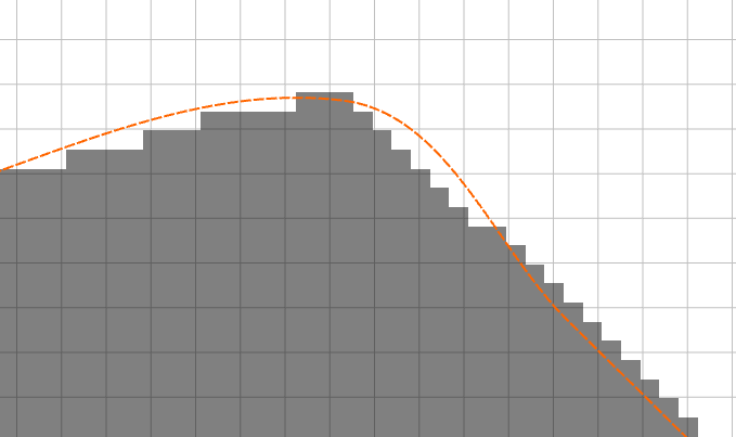
It’s a proprietary image but here’s some closeups of non chamfered sharp angles one of which goes from an angle into a curved surface.
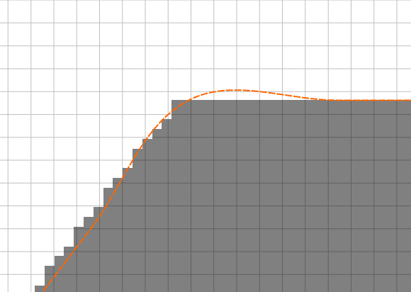
2nd one is straight left side curved right side
It’s not the end of the world and I can correct it myself (original problem was probably the standard resolution model? As when I swapped to HD and didn’t scale it down to its normal scale it didn’t happen as bad (that’s the ones pictured). So the question is does Carbide Create need to change the way it does scaling so that it is actually scaling up from the initial size instead of creating it at the initial size and applying a scale factor that scales down so when you are at your modeled size you lose resolution? Or just allow us to set scale initially before it’s generated? I’m not 100% on what causes it but something is done in a way that just sort of gets it done but probably not right. The same way that slot I gave you guys early on in this topic was scaled wrong but the rest of the model was right.
Also yes I did play with the settings quite a bit to see if anything would come out right and the larger the starting scale the more accurate it was which makes no sense unless CC is creating a tessellated image itself to convert it to a Raster pattern for tracing?
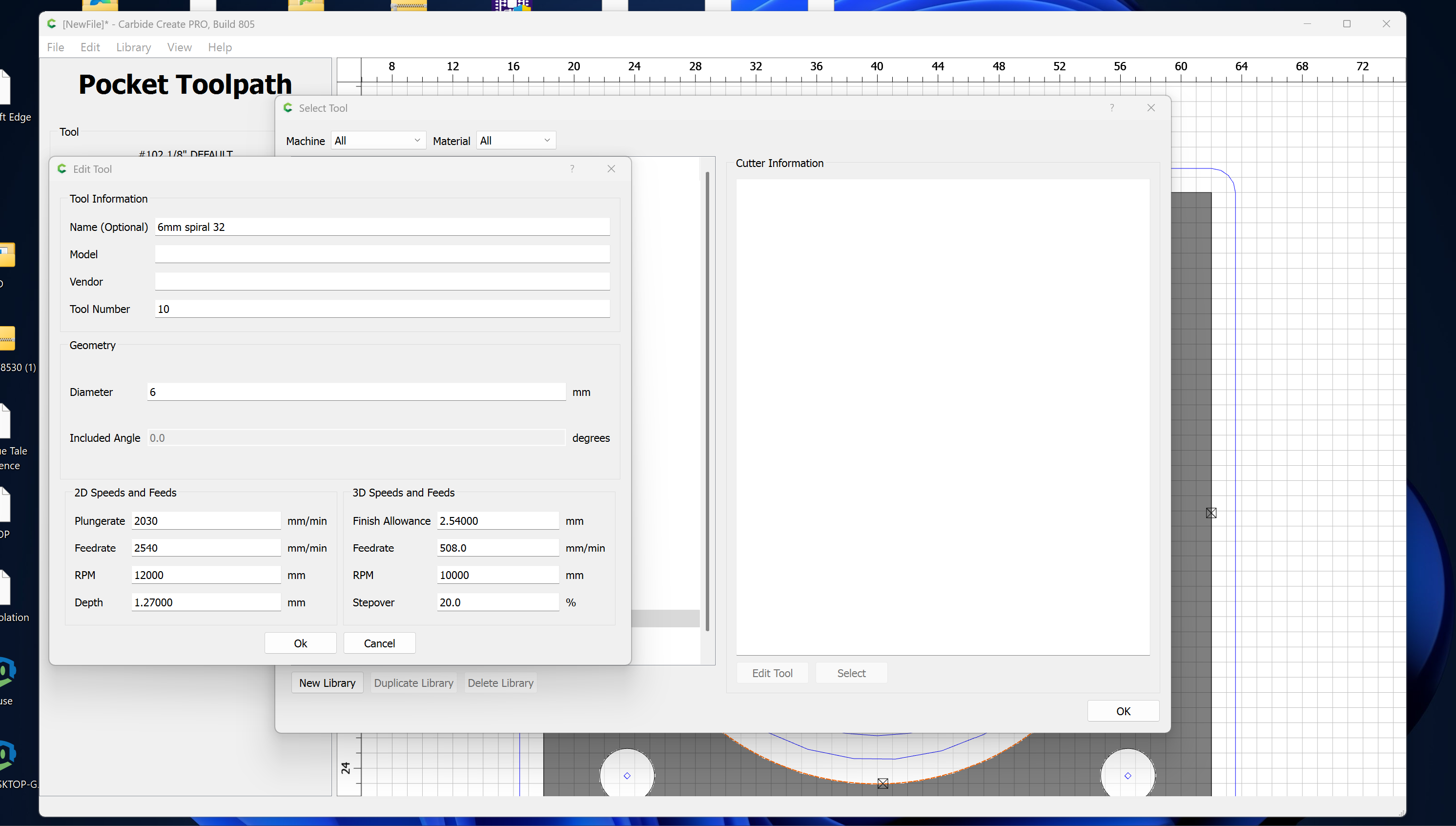
End Mill & Ball Mill have the Included Angle greyed out. It’s not relevant to those tool types.
Vee Bits & Engravers allow an Included Angle.
You will need to change the decimal separator to a period (.) in order to enter such tooling (or bypass Carbide Create and just directly edit the underlying .csv).
Just spent 2 hours plus doing what I would consider a straightforward design and all of a sudden 805 quit .Lost everything.
I am on a Mac book air m2.
My recommendation for any complicated project is to File | Save as every so often, updating the file name with a description of the current state of the project — that way if there is a problem you can restore the previous state and then try again.
If the program crashes repeatably, please upload the file here and step-by-step instructions for causing the crash (and send in the Bugsplat report if using Windows, for a Mac, save the Crash Log and send it in to support@carbide3d.com) and we will look into it.
1 Like
Thanks Will,I shall do that
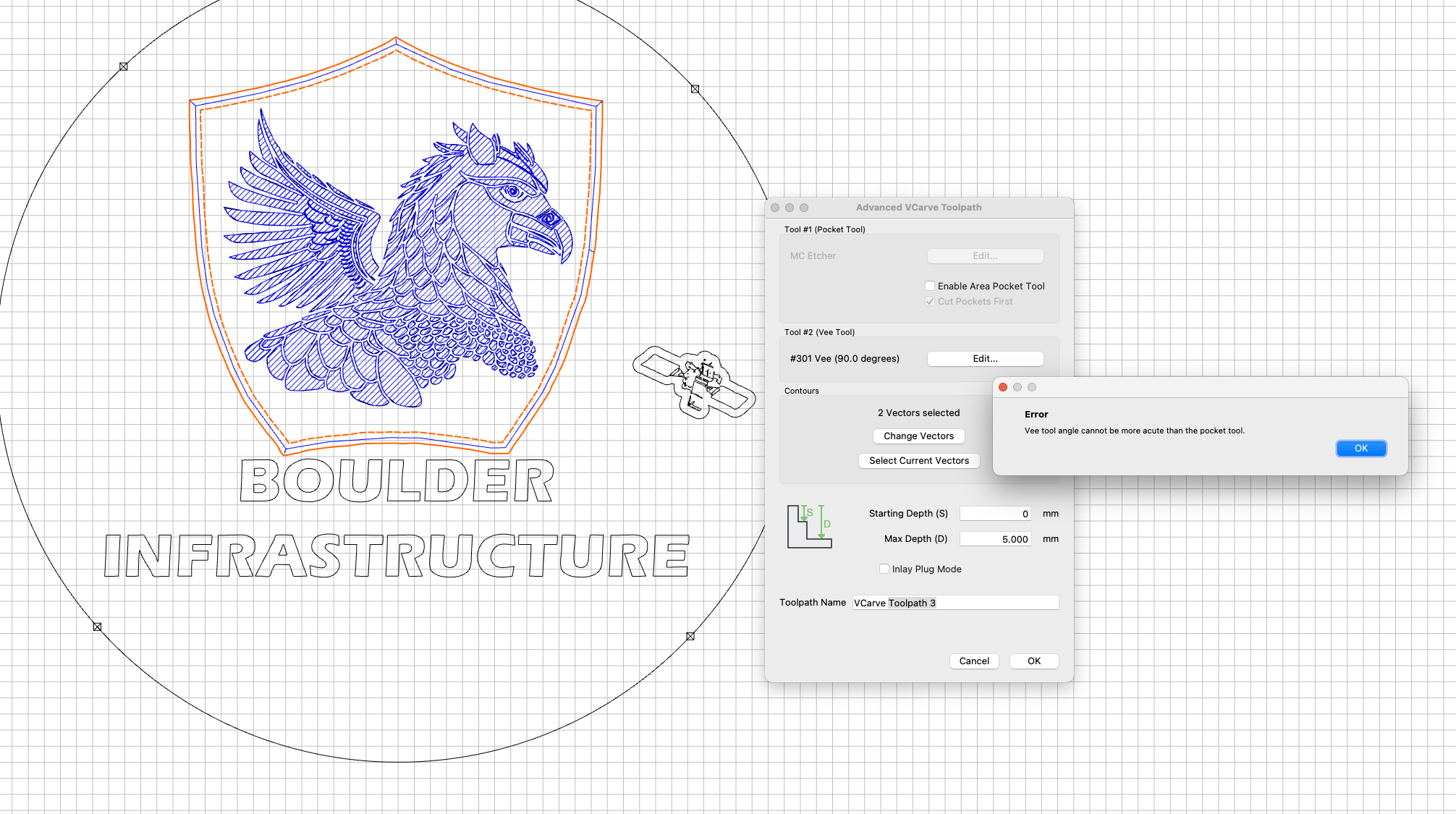
Just ran into a minor bug when trying to create a Vcarve toolpath in the 805 build. Since my previous toolpath was using the MC Etcher, the Pocketing portion of the VCarve toolpath generator was populated with the MC Etcher. Since the area I was planning to Vcarve was very small, there was no need to create a pocketing toolpath. Despite the ‘Enable Area Pocket Tool’ option not being selected, it wouldn’t let me create the toolpath and would throw an error.
Workaround: Enable the Area Pocket Tool option > Select a regular endmill to use for the pocket > Disable the Area Pocket Tool option
Not a big deal, but figured I’d pass it along.
1 Like
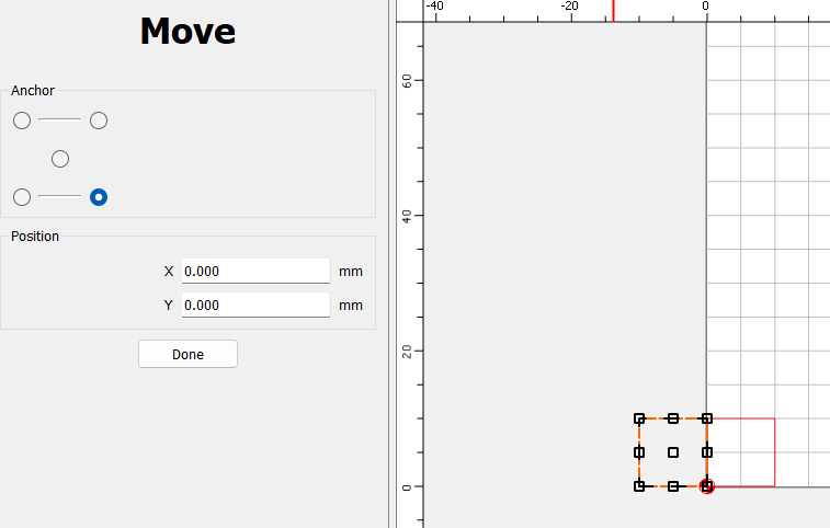
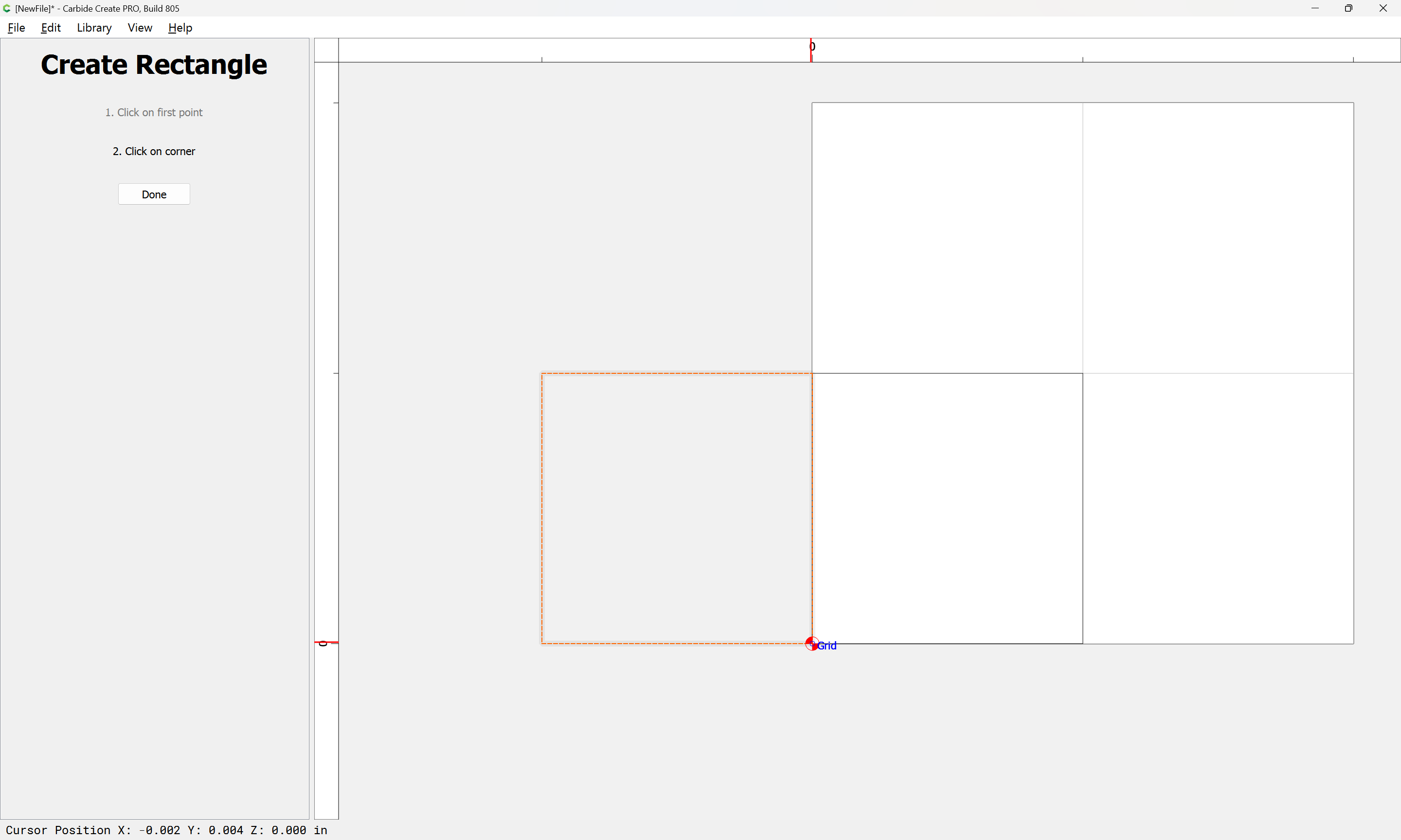
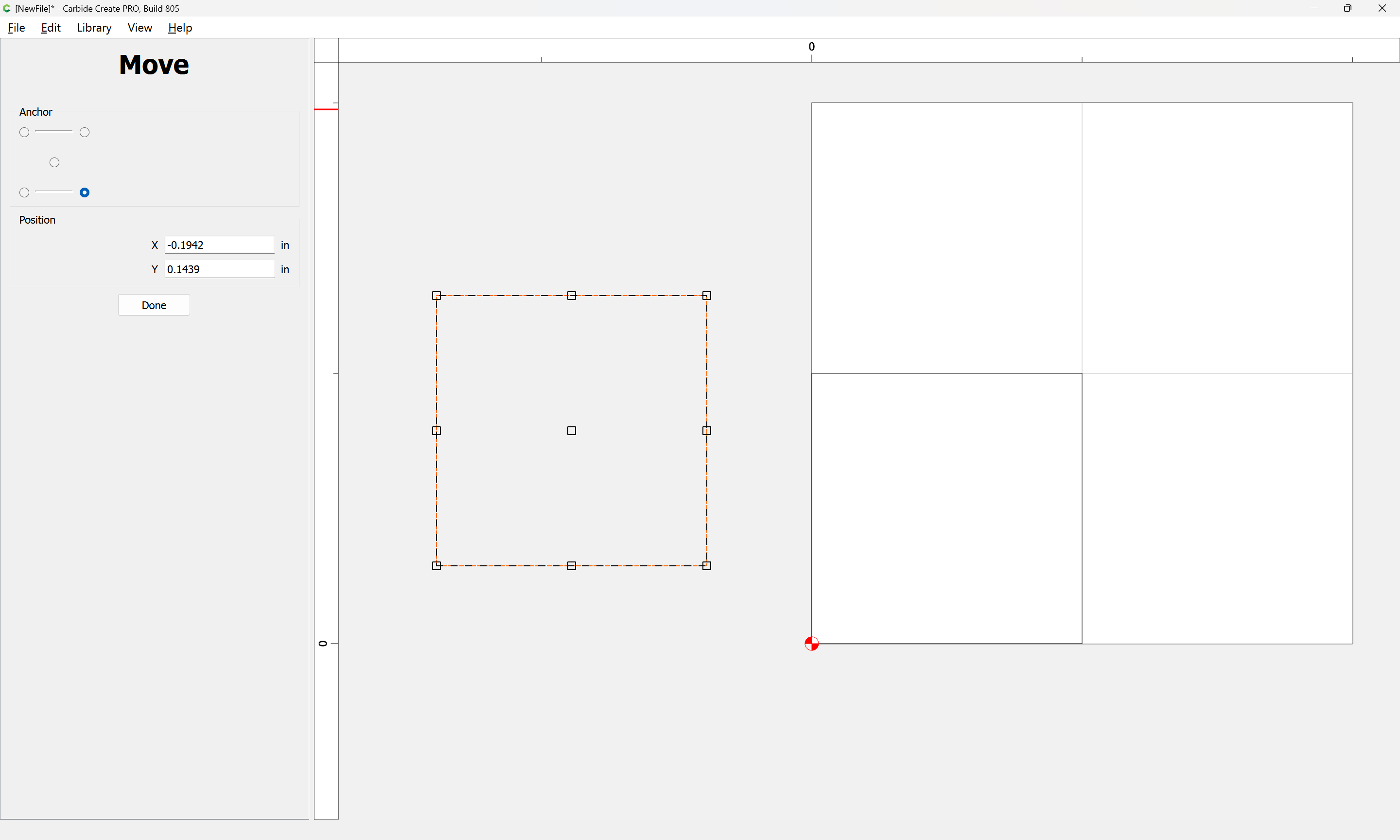
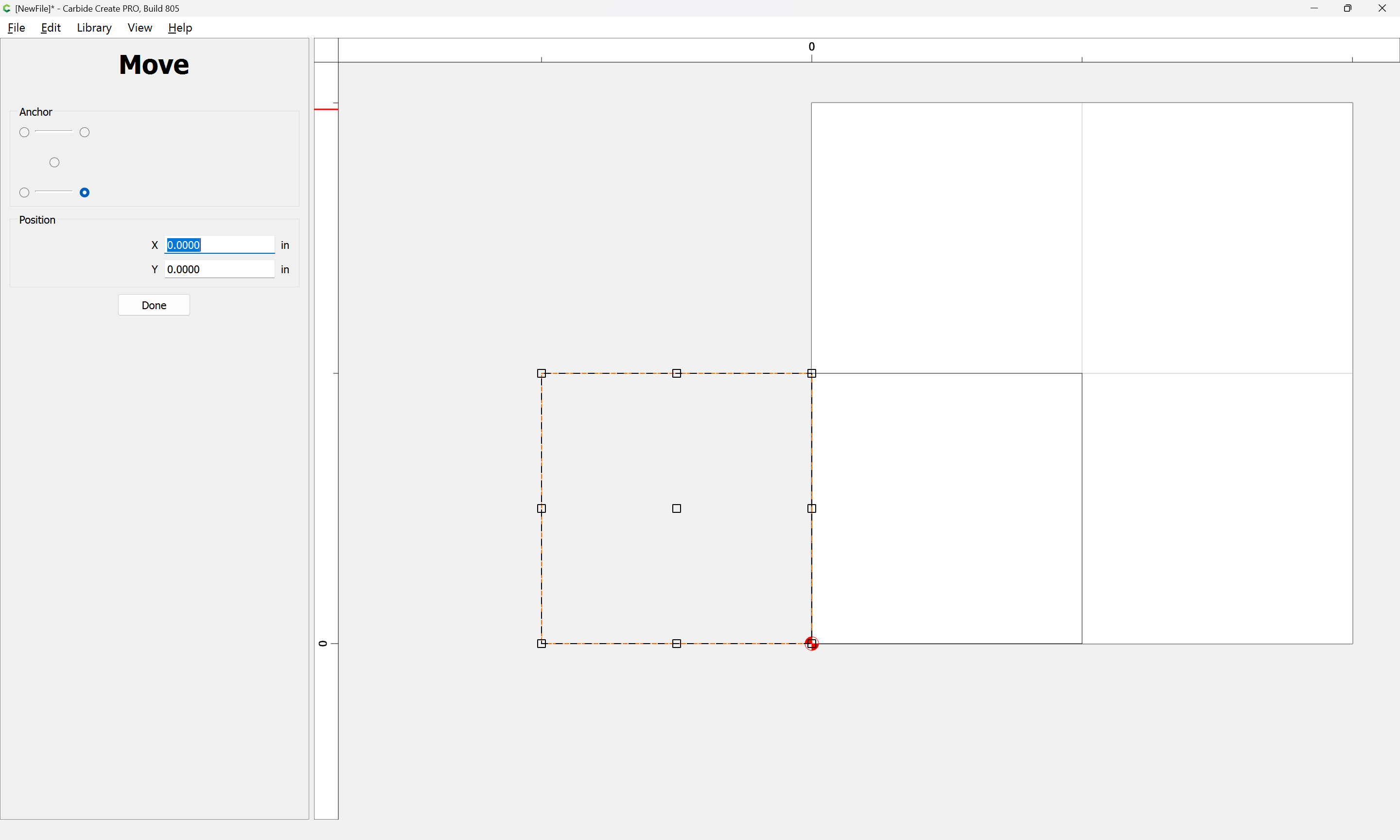
I wanted to create a box in both corners. The first one snapped to grid (toggled on), but the second wouldn’t snap to the bottom right corner. I then tried the move button and chose the bottom right corner, setting both options to zero. It still wouldn’t move there, but wanted to align to bottom left corner. Not sure if that is a glitch in v8.