I wasn’t paying attention to the timeline of when exactly the V8 beta was introduced and where we are with it today. I was close to being right at the end of my year of free updates while you guys were working on this V8 Beta. Now that I have decided to go ahead and download it, I am just past my updates. Kind of not sure what to do, or what can be done.
Even If I were to pay for an update, the Beta is still in developmental stage and how many updates would I be required to pay for before V8 is mostly completely bug free? And if updating isn’t an option, then I guess I will stick with V7 until things are settled down on the development stage of V8.
It’s safe to say Create will never be bug-free (which is no different than the software from trillion-dollar companies, based on the products I buy).
Based on BugSplat reports, we can say that other than the recent change to V-carve, which hasn’t had much testing yet, V8 has fewer crashes than V7.
I think this is the last of the changes to V8 that will change the file format, so once this build is tested, it’ll move to the stable releases. We’ll continue making changes, but they should be incremental fixes/additions.
Hello Rob, I noticed that beta version 810 release notes mentioned the fix for DXF file import scaling. So, I checked it out. I want to thank you and the software team for addressing the scaling error when importing DXF files. I have been waiting for this to get fixed for a long time and now with this beta version, the scaling is correct when importing DXF files. DXF files can be opened directly in CC 810 without having to perform a workaround using LibreCAD. Much appreciated! THANK YOU, THANK YOU, THANK YOU
6 Likes
WillAdams
(William Adams (Carbide 3D))
Split this topic
133
Been playing around in the modelling tab. There seems to be an issue with going into a Heightmap to edit the parameters generated from a STL. Sometimes when going into Edit mode, the ‘Repeart as Texture’ box will become checked for no apparent reason. And it does not respond to ‘unchecking’ it.
Fortunately, clicking Done & then going Undo recovers the Heightmap as it was. It’s quite strange as it will do this repeatedly to me. Then I’ll do something else in my project, come back to the Modelling tab it & it will work properly.
I posted this elsewhere but was directed to post it here…
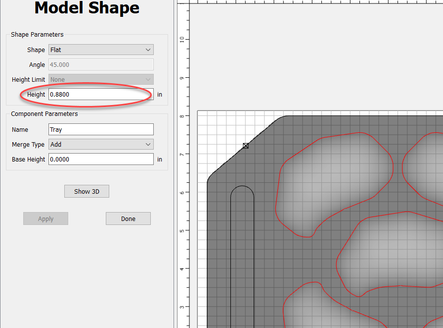
I recently built a 3D model within CC (Build 805). It’s an oyster serving tray where there are 12 3D pockets for the oysters themselves. I first made the tray itself as the first model shape. Then subtracted the oyster pockets. All worked great. However, and here is the question…
When adding the initial model shape, there is a “Height” value that can be provided. And, this can be added using the “t” variable. So, it goes and pulls the thickness value from the project settings. All great.
However, once you tab out of the field, it converts to a hard value as seen above. So, if you change the thickness in the settings, this value is now fixed and does not change. This seems to be a bug, not a feature. But I am wondering if there is a valid reason for doing this? If so, please explain. Otherwise, would be nice to have that variable remain a variable. If you forget to go in and adjust it, it does have bad consequences on the size and depth of the pocketed features.
It’s more of a design decision than bug or feature. Right now, the only entries that keep the depths as a symbolic value, rather than converting it to the current value, are machining depths. For the toolpaths, we did it more as a way to create “Toolpath templates,” which would allow you to reuse the same file using both the variables and layers to update the content.
We’d consider allowing it for model components, but it doesn’t seem like it would be as widely applicable as it is for the toolpath depths.
Thanks for the response, Rob. And I totally get your point. Just thought I would ask.
What happened: I usually enter an arbitrary thickness at design time. Then once I have milled and prepared my wood, I go back and adjust the thickness. However, the model had the original thickness value (being the surface where the 3D carve should start) which I didn’t remember I needed to change. So, I had some unexpected results in how the design was cut that created a lot of work for me unless I want to waste the the wood and start over. But I understand the thinking in your design as my situation could very well be an edge case.
I think i have a legit V8 issue. Attaching a file that works fine in 778 but in 808 it never finishes calculating the vcarve path and if i wait long enough throws an out of memory error. I did some experimentation and and i scale down the art a lot it will work, but at the size is it in the attached file it does not. Let me know if i can provide any additional details GabbyArt.c2d (552 KB)
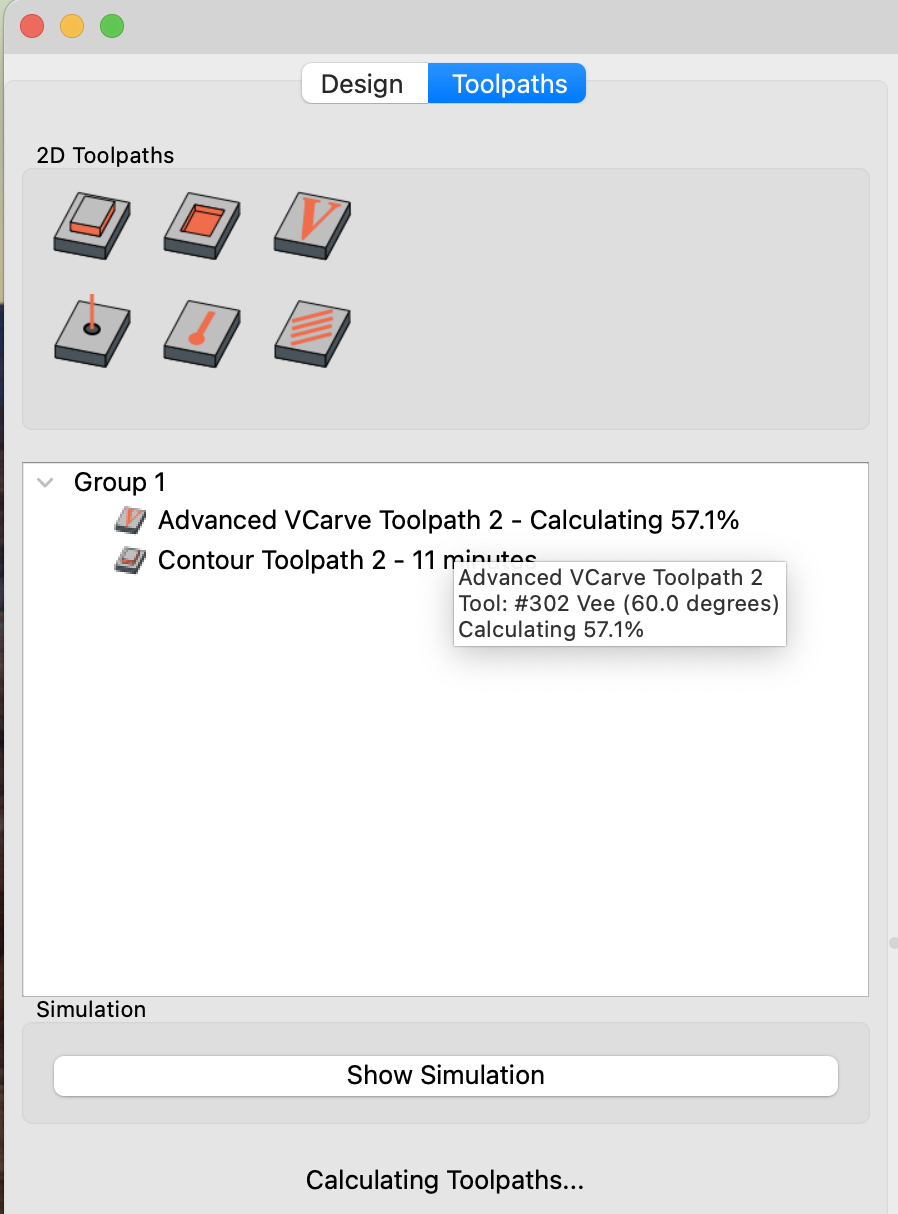
I recently tested the new feature when you can group “pocket” and “vee” paths for advanced vcarve. Means you can to all pockets first then all vee parts. Looks like there might be a bug - after each pocket cut CNC still asks to replace bit to vee, goes though bit setter, then do nothing and ask to put pocket bit back. And does this for every pocket path.
Grouped vee cuts then work just fine.
Anybody experiences the same?
Hi Mooselake, yes, I checked out the 810 fix for DXF import and can confirm the scaling is correct. Units can be what you choose in the job setup (inches or mm) and either gets scaled correctly. I sent Rob and the software team a thank you for getting this fixed finally.
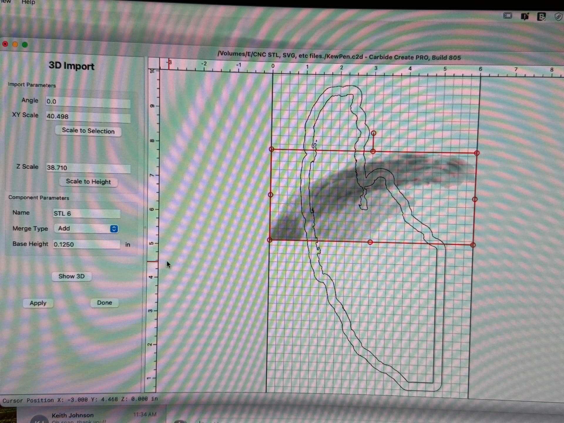
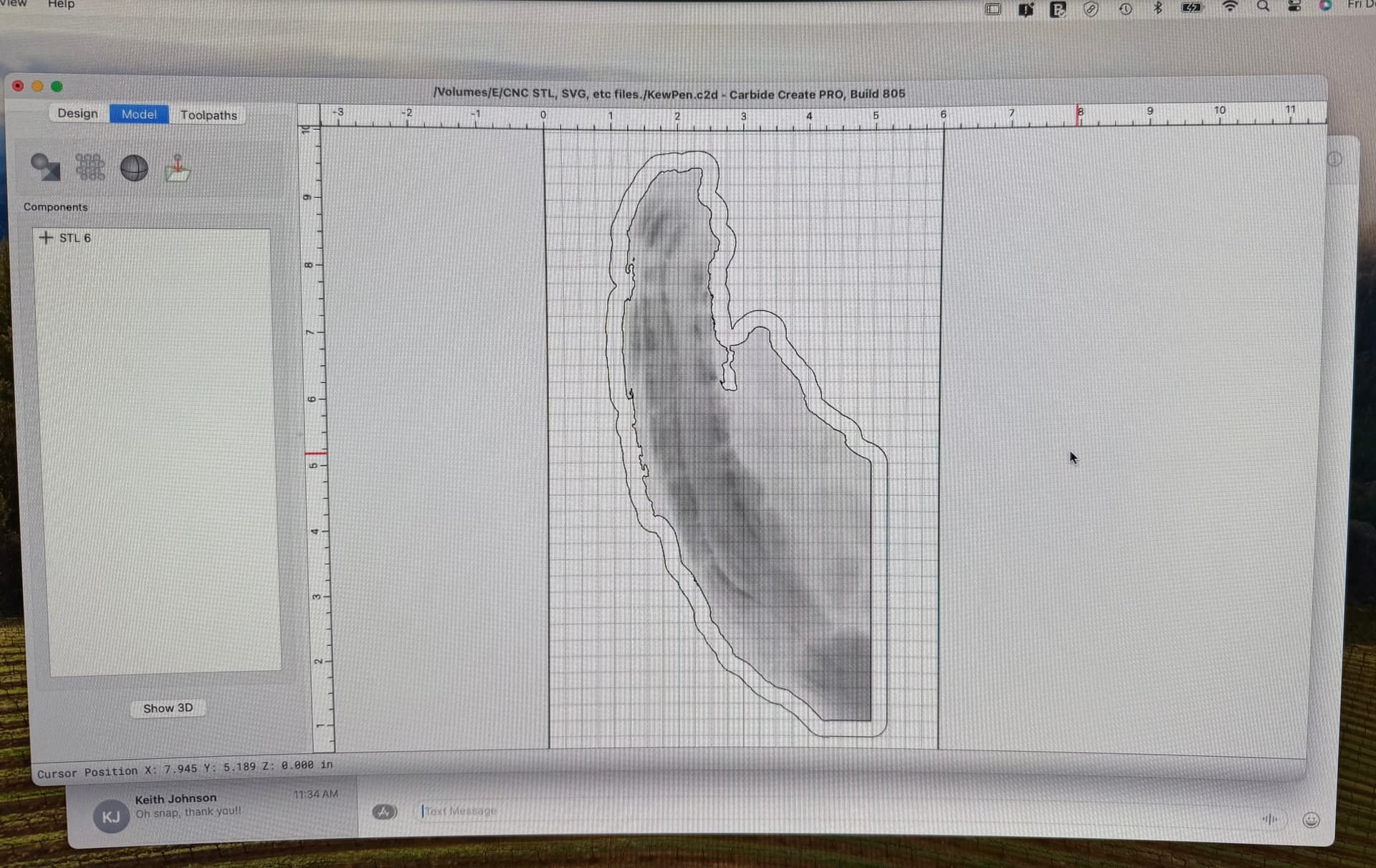
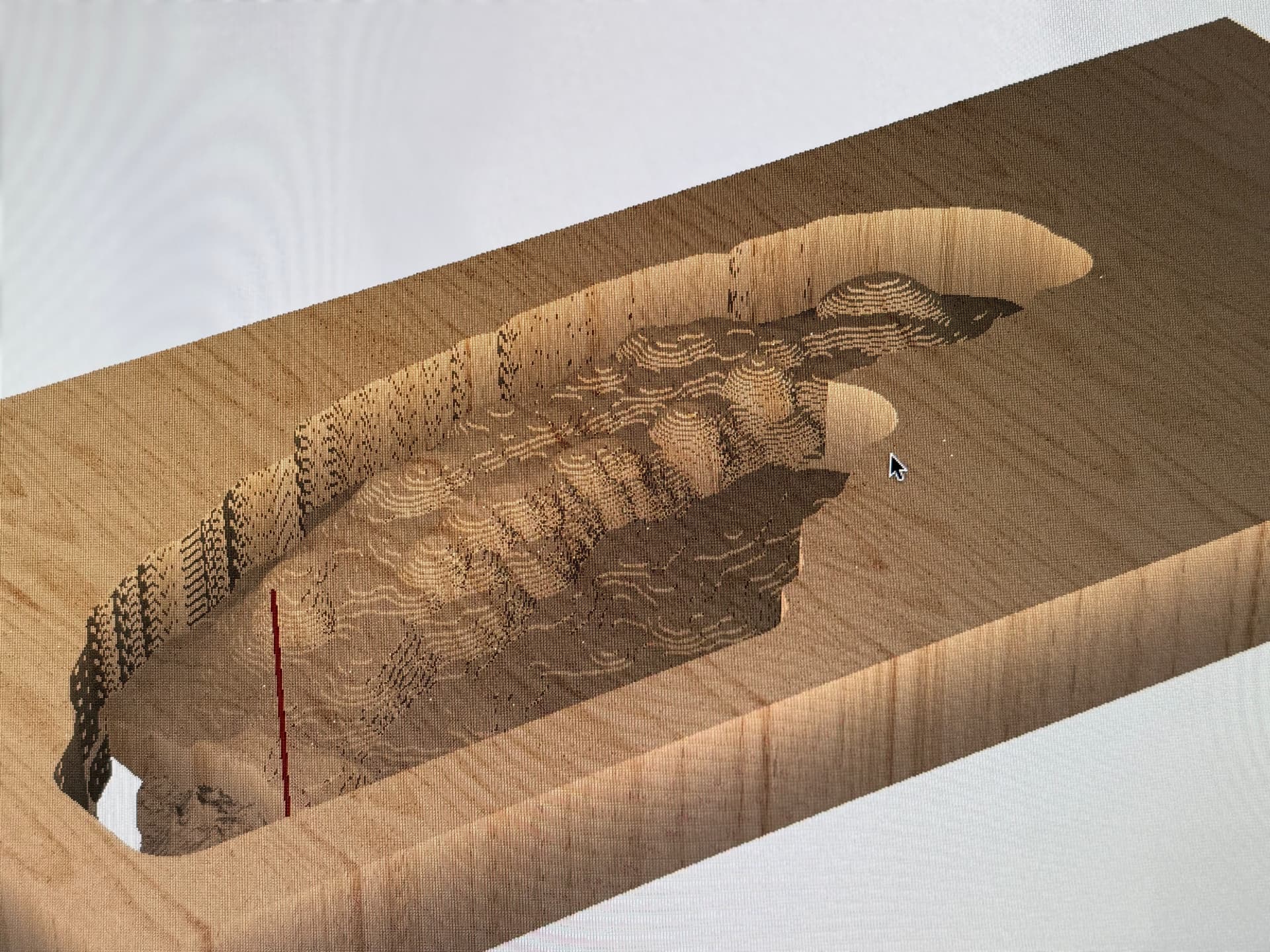
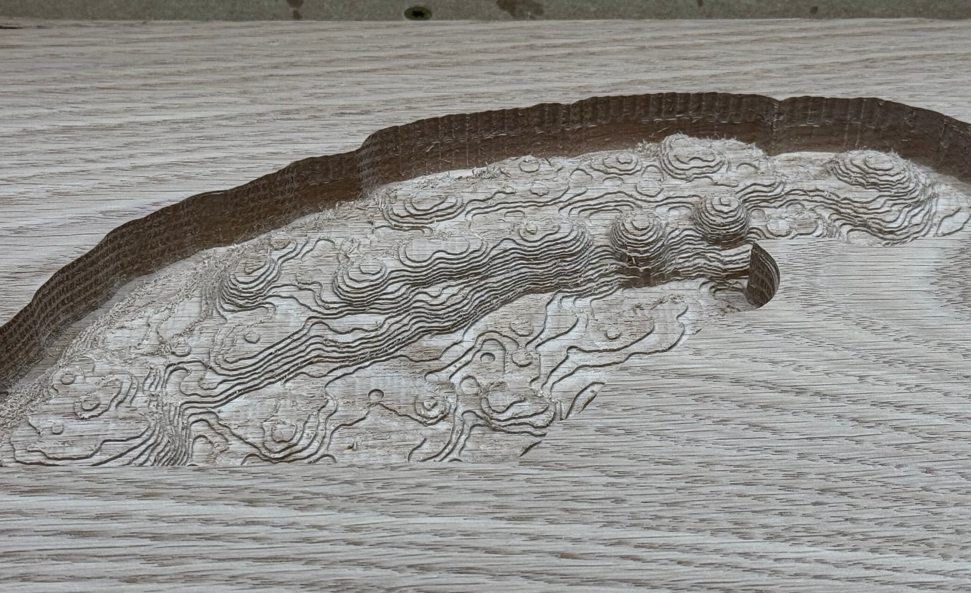
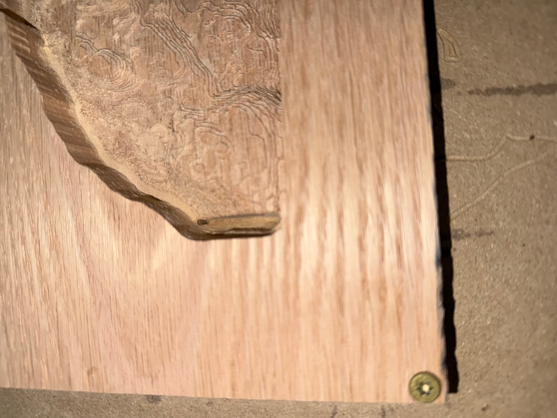
Hello, I recently downloaded V8 beta. I had some difficulty with it but due to the wonderful people in support I was able to resolve those. But now I am attempting to do a height map 3D carve and am having issues. With the design I have left a base thickness of 0.125", and also a 0.25" border around the outside of the main carve. I completed the rough carve with no issues. I used a 1/8" end mill. When I started the finish carve with a 1/32 taper, 10% stepover the bit plunged in and was carving through the full thickness of the wood and into the spoiler board. I stopped the carve. When I looked at the tool path simulation again, I did notice that the finish carve is cutting all of the way through and taking a lot of material with it. V7 I have not had this issue with other types of carves. This is my very first attempt at a height map carve and I am using V8. So I am not sure if I am doing something wrong, or is this a glitch that needs to be fixed in the beta version.
One other thing I noticed. If I go into the model section, and look at something under the +STL the screen will revert back to the position the grey scale model was originally placed before I rotated it. I have to click on the undo button to get it back in the position I want it in.
Need to create a base 3D component larger than your main carve area to keep the toolpath from ‘falling off a cliff’ at the edge of the carve. Doesn’t have to be very thick(0.001") just to give the toolpath a bottom limit.