I was thinking more along the lines of the path surfacing from the front & back(in either Conventional or Climb) until they meet in the middle to minimize wasted time lifting & jogging back like a typewriter - but I wouldn’t mind having both options. I think the important part is to have the jog movements in Y-axis beyond(or at the edges) of the defined surface so that smooth X-movement paths(or vice versa) are being made across the surface to minimize inconsistent tooling marks in the surface. These usually happen when the movement has to stop & change direction at sharp corners/end points.
CC 808 issue with DXF file import:
There has been a scaling bug when importing DXF files into CC going way back that is still with CC. I was hopeful that 808 would have corrected it with the mention of fixing importing DXF files in the release notes for 808. I have attached is my DXF file example imported so Carbide and duplicate this issue.
Colibri 250.dxf (417.1 KB)
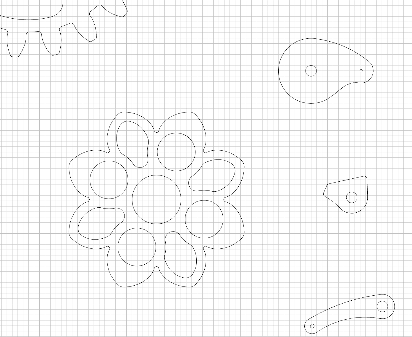
This DXF file looks like this after importing. The job setup stock size is defaults to 41.271 mm width and 27.919 mm height. The units defaults to mm. Additionally, the parts edges are not smooth with low resolution vector effects.
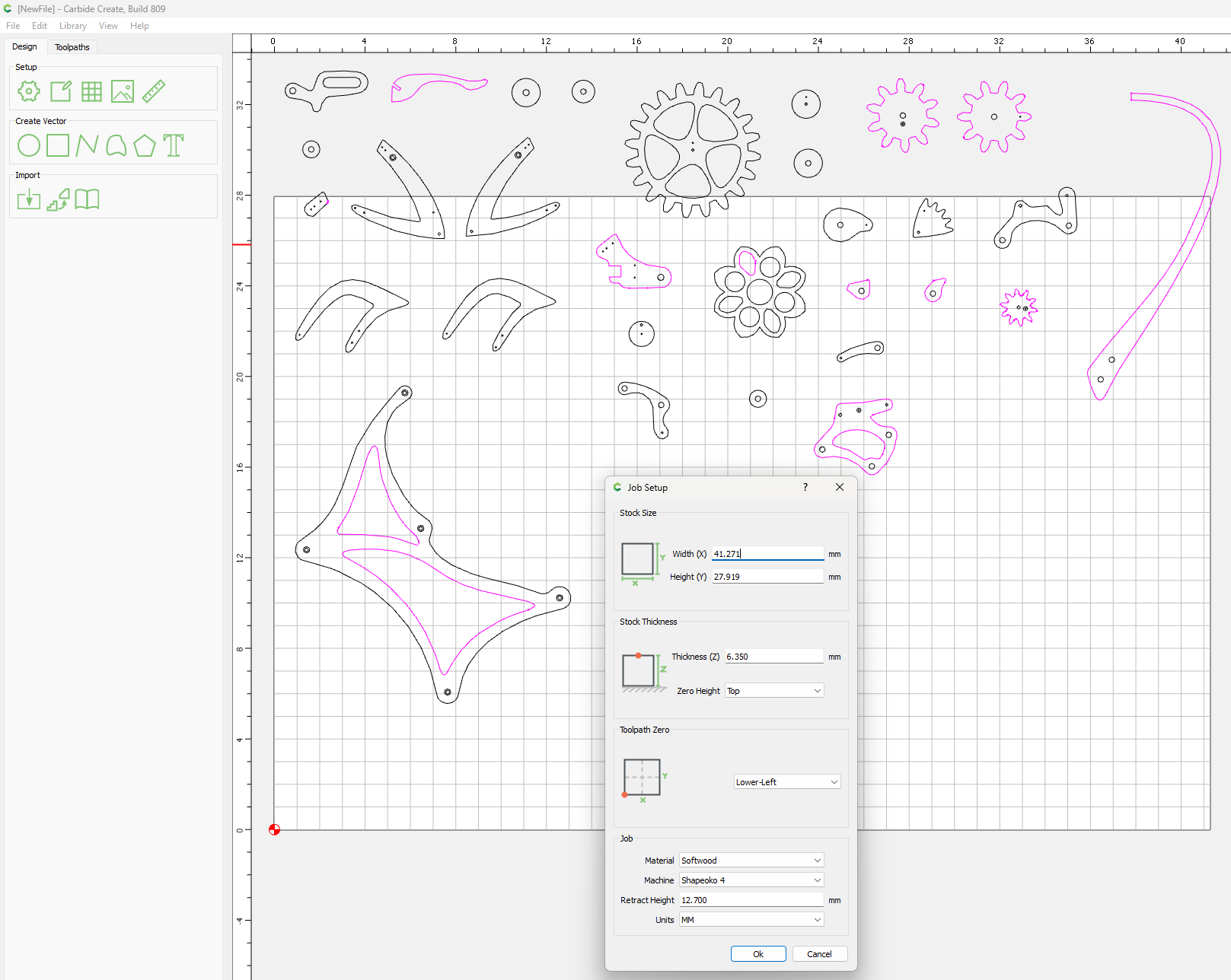
However, the scaling here is 25.4 times too small. These parts are actually larger than the CC import job setup defaults to with the stock size of 41.271 mm width and 27.919 mm height. CC imports this DXF file for mm units and it should be in inches. The CC job setup is scaled to 25.4 times too small by defaulting to mm. When the job setup is changed to the correct units of inches and by changing the scaling number from 1 to 25.4 as shown here
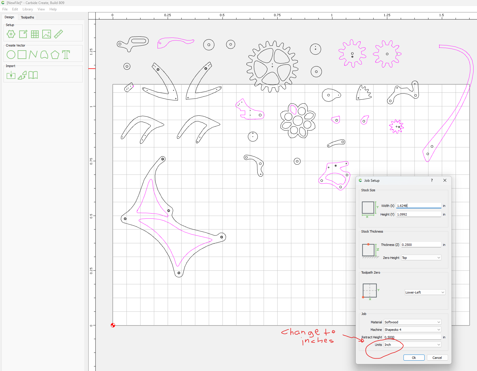
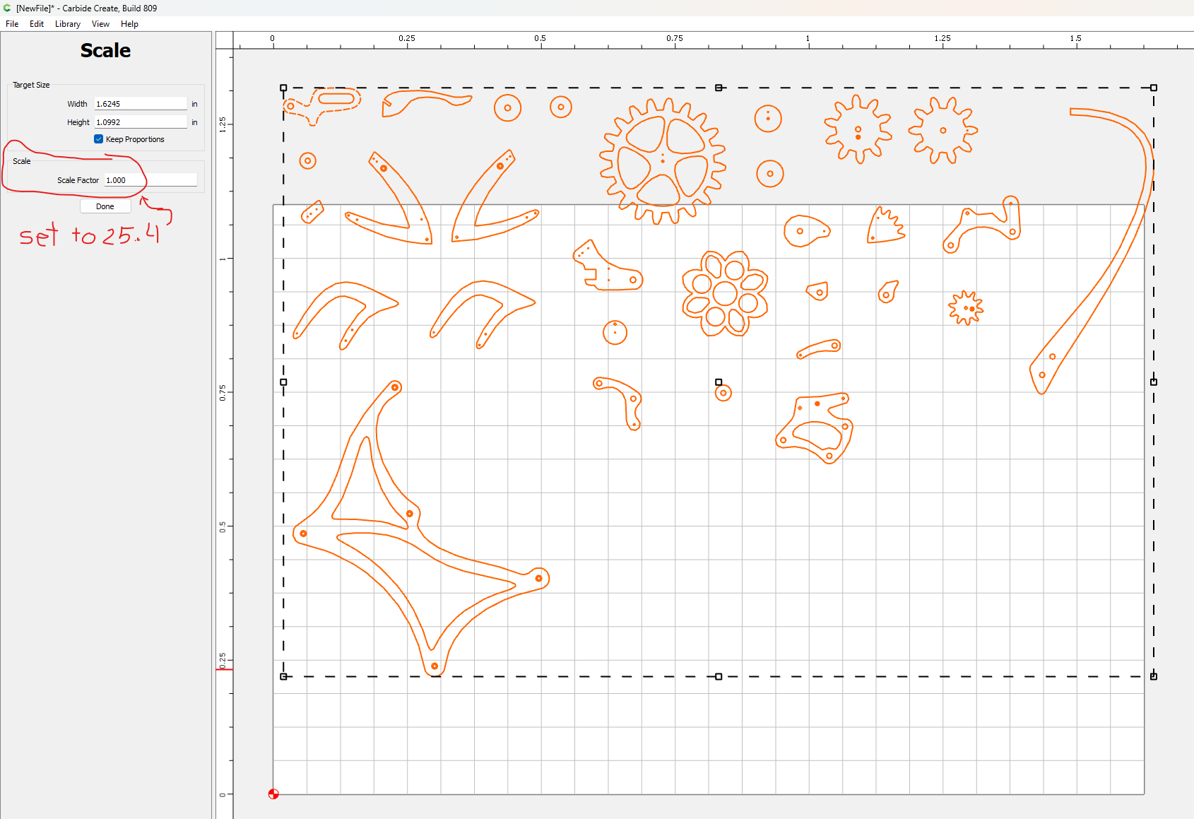
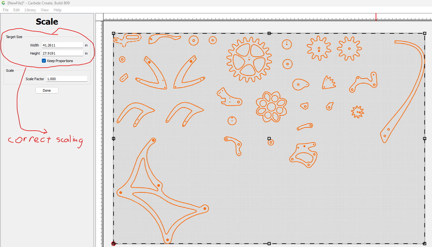
then you get the correct scaling of this imported DXF file shown like this. However, on a closer look at the parts edges you see segmentation on all of the parts edges indicating very low vector resolution.
I have made these parts and this is the correct size scaling of all of them per the drawings I have purchased, but the edges should not have this segmentation on the edges after importing.
I have had to use the work around to import these DXF files to get them scaled correctly with the higher resolution vectors and smooth edges using the support team’s method of opening them in LibreCad and them exporting them as a MakerCAM SVG file. Then importing the SVG file into CC. But this is only because CC cannot open the DXF file directly with the correct scaling and vector resolution.
This work around process results in the following imported CC file shown here. After selecting all parts and performing a join vectors the work around LibreCAD method results look like this.

These correctly scaled parts now have very smooth edges compared to the rescaled parts of importing the DXF file directly into CC. Shown here.
Can Carbide revisit the DXF import feature and get is corrected to scale parts correctly like the LibreCAD work around process?
It would be interesting knowing if the original DWF file was created with units. This article explains how to check using a text editor
As I recall, 25.4 is the magic number - mm to in conversion. We used to have that problem importing STL files, but it was resolved. Not sure if it was done for DXFs, or if it’s just that you created it in inches and brought it into a space in mm (or vice-versa)
- Gary
Just been designing up a bracket & noticed that Rest Machining does not seem to be able to correctly calculate where a 1/4"(6.35mm) bit toolpath would fit - thus it calculates extra/useless toolpaths for a smaller bit.
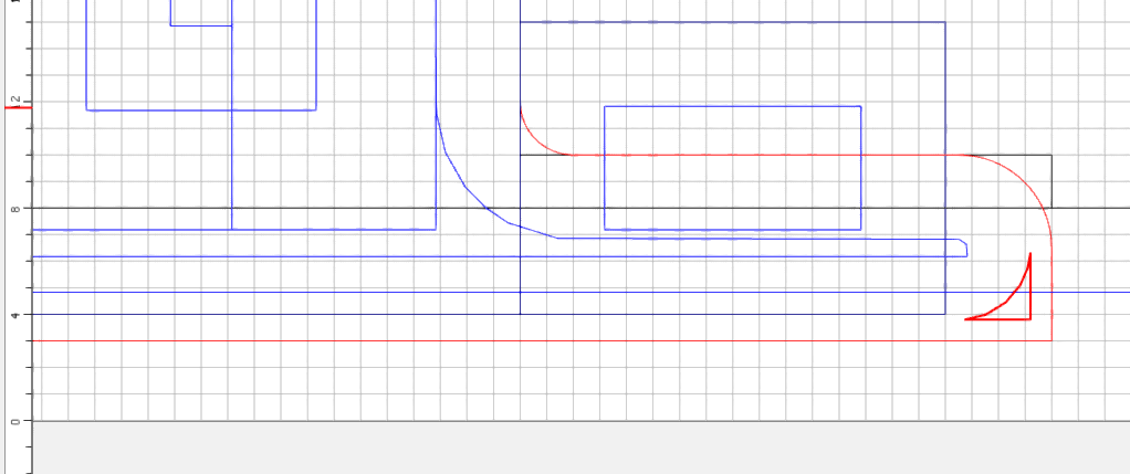
In this setup, the pocketed notch is 7mm tall which allows a 1/4" bit to clean it out - you can kind of see the Blue toolpath under the Red one. Added a pocketing operation with Rest Machining to clear out the one sharp corner more with a 1/16"th endmill, but it generates a toolpath to cleanout the entire notch.
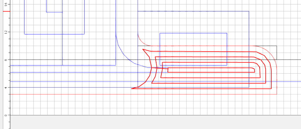
Adjusting the Previous Diameter value to 1.5-1.7mm less than the 7mm height of the notch gets it to make the toolpath I want for 1/16" bit.
1 Like
Reported before:
Short version - for the previous size bit, use previous diameter minus current diameter.
3 Likes
Hello Mooselake, I just want to remind you that in my post I mentioned that I used Carbide’s workaround to import the DXF file using LibreCAD to open the DXF and then exporting it from LibreCAD to a MakerCAM SVG file and then opening the SVG file in CC. As I stated in my post, this workaround method resulted in getting the DXF file into CC with the parts correctly scaled and displayed with nice high resolution smooth edges. This means that your question “was the DXF file created with units” is answered because the workaround approach works which means the DXF file therefore has all the scaling and units information you are referring to. Otherwise, how would the LibreCAD/MakerCAM software be able to get it right. The issue is CC is not using the scaling information in the DXF import correctly. The workaround method can get it right why can’t CC get it right. How about you, can you take the DXF file that I uploaded in my post and open it both in CC and using the LibreCAD/MakerCAM workaround to find out if you can duplicate the issue. I am hoping Carbide3D will finally do something about this to fix it. I believe CC users would appreciate this getting resolved. I have been alerting Carbide about this since CC version 5.
Hello GJM, I didn’t create the DXF file. I am just trying to open it in CC. The right question to ask is if the DXF file wasn’t created with the correct units, how is it that the LibreCAD/MakerCAM workaround gets it right, but CC gets it wrong? The conclusion is CC is not implementing the import correctly.
Not necessarily. It may just mean that the program which made the DXF and LibreCAD use the same default value for units.
Hi Mooselake, BTW I opened the DXF file in notepad and looked at the article you mentioned. Sure enough, the file is coded for inches based on the article you referenced.
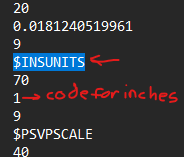
So CC is ignoring or overriding this code for inches because it opens this DXF file in CC with units set to mm.
I suspected as much. Hopefully @WillAdams or @robgrz notices your post. With any luck it’ll be easy to sort out. According to the all knowing, some telling, Giggle $INSUNITS was added in AutoCad 2000
Will, If that were the case, then the bottomline is CC needs to produce the correct resulting import as the LibreCAD method does. Because the resulting import produced by LibreCAD is correctly scaled. Importing directly into CC results in the incorrect scaling and units for these parts. You can see this problem for yourself and duplicate it because I uploaded the DXF file in my original post so it can be tried both ways at Carbide 3D. Why not give it a try at your end and see the errant file imported parts sizes in CC and then compare it to the correct part sizes when DXF file opened in LibreCAD and then exported to the MakerCAM SVG file and then open the SVG file in CC. You will CC display parts that are way too small. This shouldn’t be a difficult fix in CC.
Ok, this one is a bit dangerous. We just uploaded 810 to Carbide Create Beta Downloads and it’s got a big change that we’ve wanted to make for a while.
Now, if you create a V-carve with a pocket toolpath, they exist separately in the list view so you can reorder all of the pockets and Vees together. If you edit one, it will affect the parameters of both. If you delete one, it will delete the other.
If you create a V-carve without a pocket, you cannot go back and add one later; you need to create a new toolpath.
It works in our testing so far, but there might be (probably are) some edge cases we haven’t found yet.
Good luck- let us know what you find.
11 Likes
Ha!..that’s not a phrase that you usually want to see ![]()
I’ll give it a few shots …
- G
1 Like
I thought “Good luck” was better than “YOLO!”
6 Likes
OK…found one:
I don’t know whether it’s because the pocket turns out to be an empty path - or it’s something else (I will continue to play a little and try other cases)…but:
I start the VCarve on some text - and the toolpaths start to calculate and hang around 23-26%
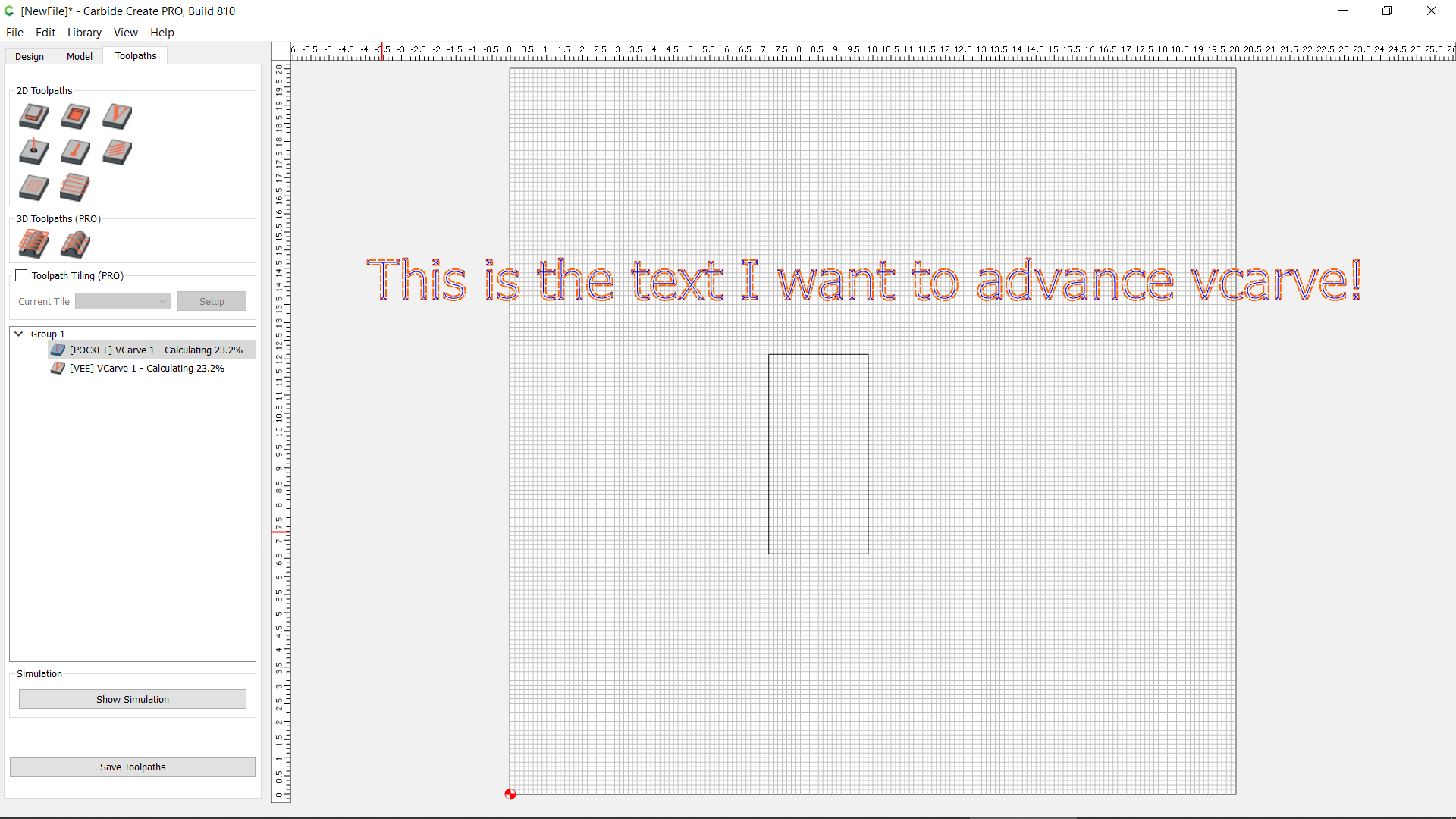
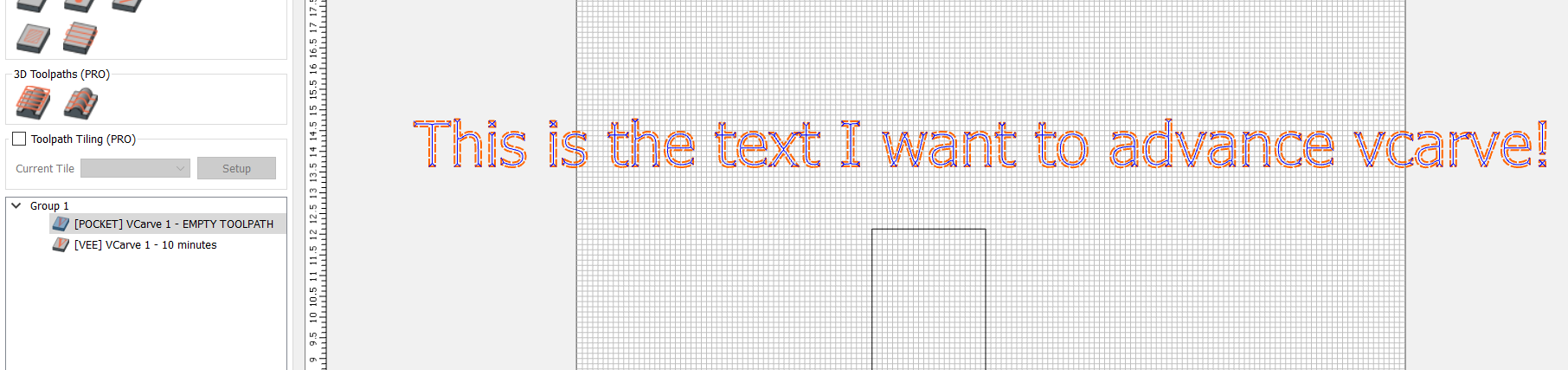
It will stay there forever - but when I click on any other window - or press the prt scr button (i.e., lose focus on CC), the screen refreshes and shows the toolpath calculations completed:
EDIT: More info. I does not seem to happen on text or on empty toolpaths…not sure why it’s happening on that specific line
Now you’re going to ask me for the file, but I already closed it without saving — will try to reproduce it.
I’ve seen that behavior, but I can’t always make it happen. That behavior should not be affected by anything we changed in the last week, so it’s tough to track down. We’ll keep looking out for it.
OK…I was able to reproduce it in this file. Just change the text and go back to the toolpath dialog and it will freeze while recalculating. I changed the font and it didn’t seem to happen…but then, when I tried to do that again (same fonts), it did ![]() so…I don’t know…
so…I don’t know…
But anyway…it’s happening with this:
simple vcarve 810 bug.c2d (332 KB)
I can’t duplicate it, but I’ll keep trying.
For what it’s worth, I don’t think the toolpath is freezing, but the progress notifications are not triggering a render when complete. Just moving the mouse over the list seems to update it.
True true true…it’s definitely not the toolpath…the work is done. It’s the refresh of the screen…the release coming back