CCPro V7 3d model renders different than toolpath sim

Hello! I’m new to CNC, but I’ve done a bit of 3d printing over the years, so I have at least some understanding of X,Y & Z. I’m using CCP V7software on a S5P 4x4. However, I am getting stuck on the rendering difference between what is shown on the 3d model, as shown here


and what I’m seeing on the tool path simulation, shown here

What actually gets carved is what is shown on the tool path simulation.
I just can’t figure out why the 3d model shows it just how I want it carved, but the stars end up being cut as a positive instead.

I wish I could go back and show my 3d model component details, but once I hit done, it’s…done. I think the wave was .35" add, the stars maybe 4mm subtract, and my white stripes .5mm subtract.

Hopefully it’s just something simple I am missing, but after countless hours searching the internet & YouTube, I can’t figure it out. BTW, I saw similar title post, but could not figure out how to add to the thread since it was already closed… Thanks in advance!

It looks like you’re including the stars in the geometry associated with the toolpath — if you do that, you get islands.

Thank you for response!
I can’t fully wrap my mind around that. It makes sense, but I’m not sure how to not do it geometrically. I am importing a wavy image and then using a template on top for carving out stars in the location I want. My understanding was that if I lay my pattern on top my carving would fall within the pattern that is already there. (Making the stars track the angles of the waves) But maybe I am doing it incorrectly. Would it be more of an order operations thing?
In my imperfect brain I am doing it like every tutorial I’ve reviewed, but I’m probably not. :slight_smile:

On top of that, I don’t understand why it worked for my stripe cutouts, but not my stars.

Post your .c2d file and we’ll walk through this with you.

Or see:

https://my.carbide3d.com/gswccpro/08/

Says the file is too big to post here. (over 4MB) I tried compressing, but get the same error message.

Mail it in to projects@carbide3d.com

1 Like

You have 64 vectors associated w/ the 3D toolpath geometry:

You want to have only geometry which defines the region to cut, so instead draw:

but increase the dimension all around by the radius of the tool which will be used:

and round the corners to save a (tiny) bit of toolpath time:

Then edit the toolpath:

Change Vectors

image

Use Current Selection

Ok

repeat for the other which gets us a bit closer:

adjusting the stepover we arrive at:

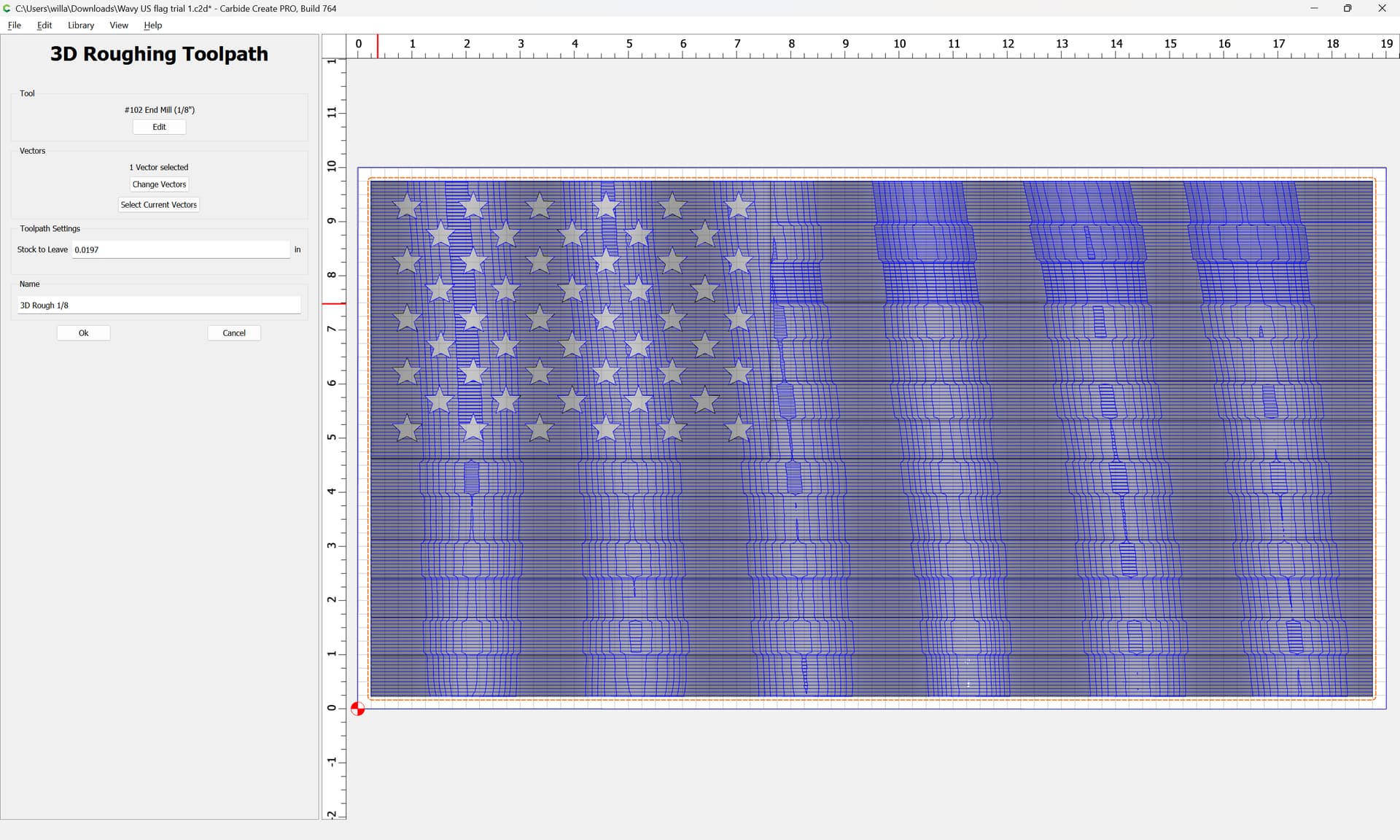
You may want to consider using a smaller tool, (so long as you don’t over-run the cutting flute length) or possibly a tool with a geometry which matches the appearance which you wish to cut.

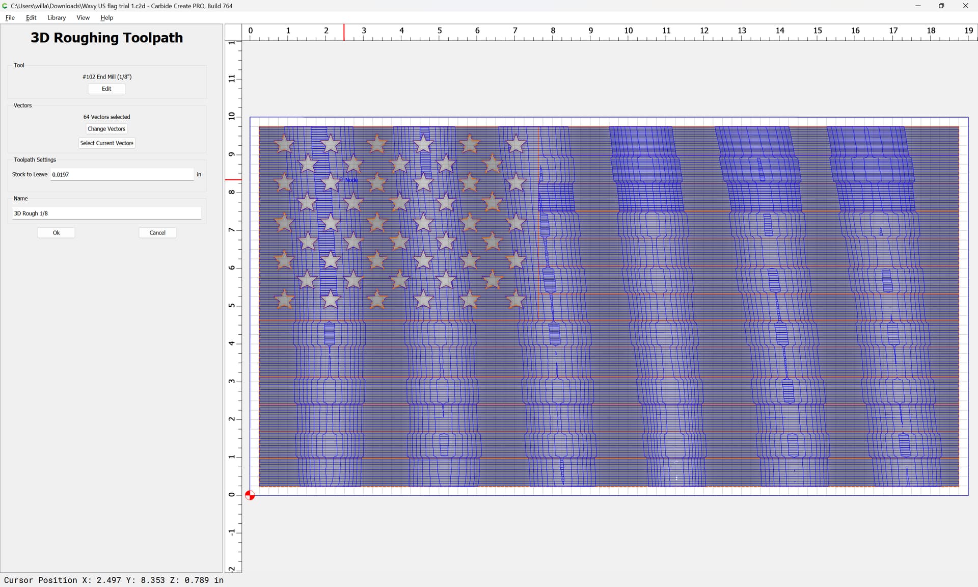
Note for the cutout profile that you don’t want to cut a slot as narrow as the tool but almost 8 times deeper than the diameter of the tool and almost twice as long as the cutting flutes on the tool.

Ideally you would use a tool which has 1" of cutting flute length.

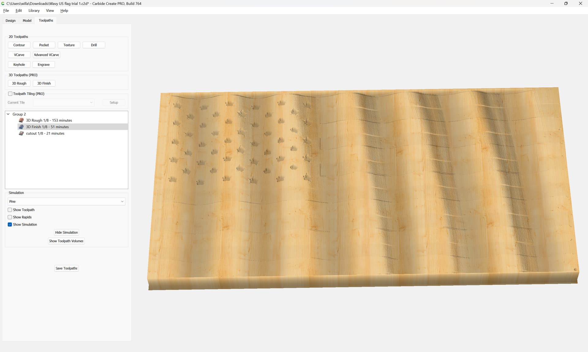
At a minimum you should offset by endmill diameter and cut as a pocket down to tab height or the penultimate pass.

Where possible avoid slotting and add geometry and cut as a pocket

and/or

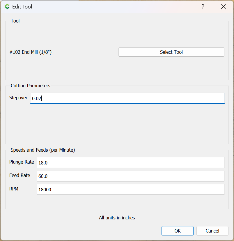
and consider leaving a roughing clearance and taking a finishing pass.

Will, you are my new hero! While I still don’t completely understand how that made it work, I got it to based on your instructions. and I have some new resources I haven’t had the chance to review just yet. I will look at those as well. Thanks so much for your help along my new journey!
Here’s a pic of it roughing out now! I’ll have to go in a little tighter on a finish path with a 1/16bit most likely too. :slight_smile: :grin:


Thanks!

1 Like

Make sure that the smaller tools which you use have cutting flute lengths longer than the height of the most vertical feature which you will be cutting with them.

Absolutely! I will probably redo the depth of the stars and trim them in a millimeter or so with a 1/16 or 1/32 to make them pointy. But thank you so much for the reminder. This was my first test run on a 3d print so I don’t need it to look quite perfect. :joy:
Or should I consider using a 90/60 vee on the stars while going 1-2mm deep?

I think stars look better when angled — perhaps try modeling them thus? That should then allow using an arbitrarily small tool to cut them.

This topic was automatically closed after 30 days. New replies are no longer allowed.