Closed loop steppers

@BartK mentioned closed loop steppers in his post in the Quiet Air Blast Setup discussion.

Anyone have any experience with doing this? I’ve see a number of versions of these on various sites with the control in the stepper driver.

I have questions:

  • If you miss a step: the pid controller will attempt to correct the miss but this will lag the plan the controller has computed. So unless the closed loop control is part of the controller this doesnt really work does it? I guess the result will be better than a total miss.

  • more interesting to me (I hope I’m not the only idiot who sometimes forgets the ground clip) is detecting unplanned motion and stopping. Anyone know if this is possible?

(The HDZ is less forgiving than the old Z.)

I ordered an interesting nema 17 closed loop stepper that uses a magnetic encoder from AMS and has source code for the controller on github… [https://banggood.app.link/tCoqknrQV1] to do some experimenting.

Norm

1 Like

Closed loop does sound interesting. However isn’t it just addressing the symptoms and not the problem? How come steps were skipped in the first place?

The shapeoko is designed very balanced with available cut force/speed. It’s not a production machine that you should be leaving alone and rely on auto stopping imo. The 125oz steppers provide plenty of cutting force (18lbs on weakest axis) yet skip easy enough to not do much damage to anything when things go wrong.

Keep us updated, would be interesting to see something like this integrated with the stock controller

5 Likes

I agree, hobbyist cnc has gotten by without closed loop control and the quality and accuracy is very high.

As I said I’m more interested in the idea of stall detection primarily for the Z axis.

Unfortunately I don’t know how it could be integrated with the stock controller without respinning the board. Too bad the stock controller doesnt use socketed stepstick style drivers… that would make hacking a lot easier.

There are new stepper drivers from Trinamic like the TMC5160 that have the ability to do some forms of stall detection using the back emf from the steppers. Unfortunately there is a minimum/maximum speed that it can work on and probing would be too slow.

My hope would be that when the expected position of the stepper motor doesnt match what the encoder is returning “following error” the program could be paused and the z immediately retracted.

I think I can also answer my first question. If the following error stays within an acceptable range then the resulting path will not have deviated enough to cause a noticable error. But that means that an external closed loop controller would need to be programmed to raise an error if it deviated too far and that would need to be fed back to cause the program to stop.

I assume you are talking about probing here?

The easiest here would be for you to ground the router so it has same potential as the probe. Then you dont need the clip anymore.

I have used similar controllers on my XL as the once you have purchased, and they have a “homing mode” where the current / torque will be reduced, this can be programmed for the stepper to stop once a certain angle of deviation is seen. (Z axis not stopping during probing)
The idea behind this mode is to preset/home your machine against mechanical limits using slow speed and reduced force on the steppers without using the homing switches.

I did some experimenting on my XL with the closed loop controllers supplied from misfittech
I prefer calling these “single axis closed loop control” to avoid confusion.

After installing these on all axis and ran for a while with only position feedback active, no position control. I realised fairly quickly that I dont push my machine so hard that I will be needing this. The estimated position and calculated position was bang on after long jobs in aluminium.

In my opinion there should be no use for closed loop control on these machines, if its assembled correctly and you find the limits of your machine and operate within that, we can fully rely on the “Estimated positions”. However if the machine is being pushed to its limits and steps are lost, this is a indication that the mechanical load on the stepper is too high / overloaded.

Also, if you lose steps on for example the X axis, the CNC controller will not be aware of this (neither will you until you see it on your work), and therefore it will not reduce the speed of the other axis for the X to correct itself to prevent damage to your work. So in case of lost steps, there will be damage to your work, the damage will however be reduced as the standalone closed loop controller will notice the deviation and “immediately” correct for the deviation.

The standalone closed loop controller for each stepper will not give any higher accuracy of your machine.

Im currently using the closed loop feedback for testing of accuracy and repetability on different types of swithces for homing. This is in my opinion the weakest link when it comes to precision on our machines. I will make a seperate thread for that once I have all numbers ready.

EDIT :Please excuse my english as this is not my native language.

It has an errorpin that is set high if the “following error” is greater than a set limit. This can be wired to the door switch on grbl in order to stop the program and the other axis.

These are called a servo. The way it works is by having what amounts to a smart controller monitoring the current position, and the targeted position, usually with a PID capable controller (Proportional, Integral, Derivative). They work quite well in many, many situations, and work well here as well. The nice thing about them in this case is that they have the same interface to the controller as a regular stepper - step, clock, etc. They don’t “miss steps” they increase torque as appropriate to make the step, and if there is insufficient torque in this application, it keeps applying it instead of simply “giving up” and missing a step. With a cutting too, that means as the tool cuts, the required torque will decrease, so effectively, it can’t “miss a step”. The whole process is pretty cool. There are open source solutions that strap onto a plain old stepper, but don’t seem to have gotten much traction.

In this situation, it’s not easy to hook them up to the stock carbide controller - they simply aren’t set up for external drivers, which is the capability you need to do this. I’m using a SuperGerbil board to drive my external steppers, and it works quite well. Not perfect, but I’m happy enough and have line of sight to fixing the problems I have (I can finally build code for it!) . I haven’t bit off servos - they’re pretty expensive compared to a stepper (they add a set of hall sensors to the motor assembly itself, and the drivers for them are more expensive) and I find I just don’t need the extra capability. If I was made of money, I might try it on an axis (if anything, maybe Y) but again, not really necessary.

My 2 cents.

3 Likes

The one instance of it in hobbyist opensource I’m aware of is the Lobo CNC — my understanding is it depended on inexpensive encoders from a stock of PS3 controller repair parts — when that source dried up it stopped being commercially viable.

The most interesting aspect of the design was the positional encoding facilitates manual use as a manual mill with DRO.

I have also looked into upgrades as far as motors go

Closed loop steppers are barely an upgrade, they will just halt if the following error becomes higher than the set threshold.

Servos are king: they use an encoder to move to a position, regardless of how many steps it takes to get there. You can also drive them in step mode but the still look at the expected position and adjust as required.

I reckon 400w DMM servos would be perfect for the SO3, alas the price makes it an uneconomical upgrade for me

Using closed loop steppers on the ballscrew driven so3 helped me find my machine’s limits without putting unnecessary stress on the components. Using too high accelerations and speeds on a dual ballscrew driven axis might result in one of the motors stalling and misaligning the gantry, which will not be a pretty sight. The entire machine will twist like a pretzel - putting a lot of stress on the joints. That might loosen the bolts, causing further damages. Sure I could lower the accels and speeds, but how do I know that I’m maximising my machine’s potential? This will most likely not be an issue with a belt driven machine, as the motors and drive system don’t have enough power to cause any damages to the machine’s frame? At least that’s my experience with belt and screw driven hobby cncs. Like most of you said, it’s absolutely not necessary to use closed loop steppers but I like to believe that if there’s even the slightest chance of something going wrong the controller will throw an error and stop the machine - and I’ve had that happen many times when fine tuning my so3. Especially during jogging, because CNCJS doesn’t allow for adjusting jogging speed unlike UGS does. Now, let’s say, one of the ball screw bearings might start giving up after some time, or bolts that are holding bearing blocks will loosen. This is something I won’t be able to notice, but the stepper driver will. Besides, this topic only makes sense to those who changed the controller on their so3 and use external drivers. Closed loop steppers cost only slightly more than open loop ones with external drivers, so why not? They also come with much longer cables - something you normally don’t care about unless you build your own system and realise how much PITA wiring really is. You guys don’t have to worry about it because Carbide3d solved this issue for you. Just my two cents.

One thing I’m uncertain about is - I’ve crashed my machine (without closed loop steppers) due to an error in a tool path - I had a 3/8 end mill try to slot 6mm deep in aluminium. Clearly that’s something in a vmc territory not a aluminium router. 3/8" is too thick to break so the machine without a feedback loop was trying to continue executing the program, but the cutter was stuck. It was a new code, so luckily I was babysitting the machine and hit the
estop immediately. What if I weren’t around? The results would be catastrophic. Will the closed loop steppers stop execution of a program in such case?

3 Likes

I have closed-loop steppers on my HDZero (Luke’s CNC project, before he joined Carbide. Think the HDZ scaled up to a whole CNC) and I’m happy with my choice, but I don’t know that they make a lot of sense for a Shapeoko. I really like that my system will stop when something goes wrong, rather than trying to break things even harder. It’s also helped the couple times I’ve accidentally mis-calculated my machine’s limits–once I tried boring M12 holes slightly too close to the X limit, and instead of a completely broken run with lost steps and everything being crooked, I ended up with the last row of M12s having a flat on one side of the circle. It also makes it really obvious if I over-drive some component, and made tuning easy.

But, the performance limits on my CNC aren’t really stepper-related. On paper, I should be able to do ~22,000 mm/min rapids, but ballscrew resonance limits that to ~15,000 mm/min on the X axis. If I go faster it’ll start shaking and then the steppers fault out. I’ve cranked acceleration up a few times, but my table wasn’t solid enough to accelerate at the limit of the machine, so I backed off. In just about every other case, the limit is either my endmill or my spindle, and I end up with either a broken chunk of carbide or one filled with melted aluminum.

The closed-loop steppers don’t help at all with accidentally ramming the endmill into the surface and breaking it. Nor do they help with using too high of a feed rate and stalling my spindle (I should really upgrade to something with more torque). In both cases, I end up with broken endmills, but rarely any more damage (although I killed an ER16 collet once by breaking the endmill and then ramming the stump into the collet).

I don’t think it’s really possible to get 4 closed-loop steppers for much under $500, and I don’t think there’s any way to drive them with the Carbide motion GRBL board, so you’ll have to switch to a GRBL board with support for external stepper drivers. Which probably means that Carbide’s software will stop working.

All in all, the thing I probably like most about my steppers is their really, really low inductance. Leadshine lists them as 1.18 mH, which is really low. That means that their RPM/torque curve is much flatter than most steppers, which means that they have enough power at high speeds to actually be useful. They’re actually more torque-y at 2,000 RPM than pretty much every NEMA34 stepper that I’ve seen. All in all, they’re only slightly worse than AC servos would be, and servos would have cost ~3x as much and been really hard to mount.

As for BartK’s question: would closed-loop steppers protect from stalling a 3/8" endmill in 6mm aluminum? Probably. I’ve stalled 1/4" endmills in 1/4" aluminum, and the endmill broke first. I suspect that with a 3/8" endmill, one of my steppers would fault before the bit broke. That is, unless the machine was in the middle of a high-speed rapid move when the endmill hit the aluminum. If that happened, then I suspect I’d have more damage than just a broken endmill.
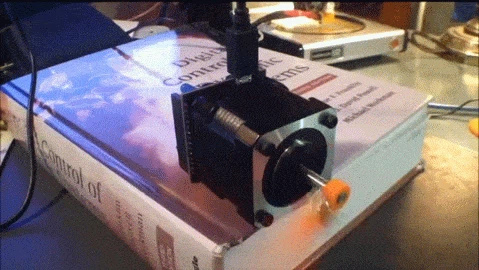
5 Likes

@ScottLaird Thank you for this perfect explanation. This is exactly what I needed to confirm.

Unlike servo motors, isn’t the torque of stepper motors limited by the current limit set by their drivers and their power supplies? So, isn’t the ability to electronically (rather then audibly) detect skipped steps the only real advantage of closed loop steppers?

1 Like

Same underlying technology - the servo motor also increases torque with current, it’s just that the current is basically regulated based on position - if off position (overshoot or undershoot) the current increases in the correct direction to bring it back into the correct position. Put force on it to bring it out of position and the current increases to bring it back into position. In a CNC application like this, they’re usually “overdamped”, which prevents the overshoot case as long as you aren’t actually hanging onto the spindle and trying to drag it around.

This had some promise, but I guess never really got traction:


image

1 Like

Back to steppers. ShopBot has options for both open and closed loop steppers on their more expensive machines. For the closed loop option: “With constant positional feedback to the drivers, if an obstruction is hit or cutting too fast the drivers will attempt to correct the position of the motors before activating an alarm, stopping the machine and displaying an alarm on the monitor. Once reset and homed, cutting should be able to be resumed.” But, isn’t “positional feedback” likely just motor shaft position feedback from an encoder?

1 Like

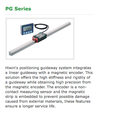
Wouldn’t rails like these enable to accurately define machine’s position?
30

2 Likes

That’s more like what I think of as “position feedback”, but the position sensors would need to be fast and accurate enough for the feedback loop. Torque control of the drive motors would then provide the ultimate machine! Does anyone do that?
OOPs - the controller would need to monitor spindle power too!

1 Like

Adding some sort of absolute linear encoder (like BartK’s linear slides, above) would be cool, but integrating the inputs from those and motors is way above GRBL’s abilities. I think some people have done similar with LinuxCNC, but a minimal LinuxCNC controller with modern hardware is around $500. In theory that could drop to ~$200ish with a RPi 4 as a controller, but I don’t think it’s really stable enough yet.

I have no idea how much those HiWin encoders cost, but I’d be amazed if a full set of them could be had for under $1k. I’d guess that they’d be closer to $1k each. I’m not really sure what that’d buy you in an aluminum-extrusion CNC, given how flexible the frame is. There’s no point in being able to measure axes to the nearest micron when the whole frame can flex 50-100 microns.

They’d be a great solution for the “my homing switches aren’t accurate enough,” though.

Monitoring spindle + drive power is probably interesting, though. I’m in the middle of moving my HDZero from GRBL to LinuxCNC, and I’ve included spindle and individual stepper power monitoring in the build. I should be able to collect power stats at ~1 kHz (although I’m not sure how useful that is with AC). That should be enough data to detect things like burying a 1/4" endmill in aluminum before the motor completely stalls and breaks the endmill, but I’m not sure what I can really do with that data without creating a false-alarm problem that’s bigger than my broken-endmill problem. It’ll certainly be useful for monitoring and optimizing cutting performance, though.

Based on this, I doubt that those types of encoders are accurate enough over the required X and Y spans to be of much use anyway. Some sort of optical or independent mechanical sensors are likely necessary.

IMO it would be difficult to measure stepper motor power and there’s likely little value in measuring it. But, there’s lots of value in measuring and monitoring spindle power and it’s easy to do.

If you used the linear magnetic encoders from AMS you can get 14 bit positional accuracy for every 2mm. That’s a lot of accuracy. Even with the ± 2 lsb claimed on the data sheet that’s .02 thou! It uses a magnetic strip that has individual magnets bonded together into a long strip of alternating magnetic poles.

Interesting devices. Any thoughts on where to get magnetic strips meeting the length and accuracy requirements?