How did you establish the original scale of the geometry ?
I’m sorry, I don’t know what that means.
I used Sketchup for many years but it will not export in the format needed for CNC.
I believe jtclose is asking you what is the scale of your parts? How do we know what size to make them on the cnc?
Export to DXF (first) or SVG. That will give you the path to whatever CAM system you would use.
Be sure the arcs you created in Sketchup show up in the target system.
That is acceptable to Carbide Create to import
DXF has many versions, if you have an import issue on the CAD/CAM side, try an export and older version from Sketch up. Real old systems may require version 12.
There are a number of options for using SketchUp for CNC.
As noted, it should export DXFs:
https://help.sketchup.com/en/sketchup-education/exporting-model
and there is a free STL export:
and there are also various CAM options directly w/in Sketchup (let me know if we need to look those up).
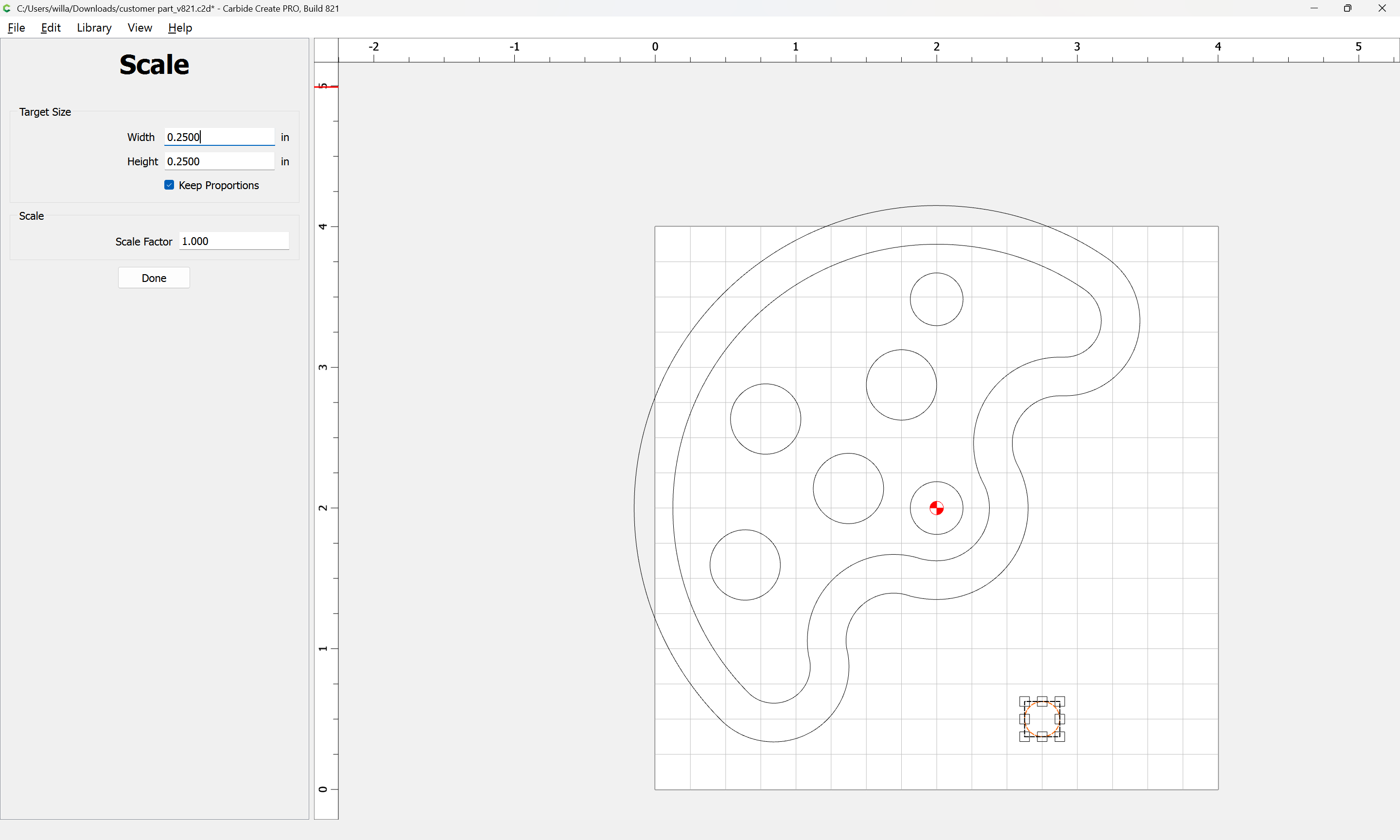
I’m trying to be careful here with copyright laws and all. I scanned that drawing from the plans. It’s on a 1/8” grid with the darker lines being at the 1” points. The diameter of the large outer circle is 3-¾”. My intent of those whole thing is to determine if a CNC fits into my workflow. My experience with the small pieces on these models can sometimes be difficult. They get more complicated when: 1) There are multiple copies of the same part and 2) These parts are connected by a dowel so they must all be exactly alike and in line. So my original query was to determine if the time taken to reproduce these parts in CAD, is worth it. Right now I can convince myself either way that I “need” a Shapeoko Pro. Certainly not for all the parts, but for ones similar to the sample that I sent. My model building goal is to make the moving parts line up perfectly and move smoothly. Thank you all for the responses you’ve provided. I will certainly look further into the Sketchup add-ons.
In that case, scaling to 0.5 should yield the desired result:

That leaves the last question of, “What stock thickness?”
FWIW, IME, if one views CAD and CAM as digital fixturing and jigs and machine setups, then it is faster, and it increases the efficiency of machine time, since setups/workholding for CAM go much more quickly than setting up a traditional tool.
1 Like
The thickness of this piece is ¾”. I agree that a CNC will improve the efficiency of a work flow if the user is familiar and comfortable with the software use to create the part. For me, that software would be Sketchup. I read early on that Sketchup wouldn’t work, but one of the responses in this forum pointed out an add-on that will allow it to work. If that’s the case, I’m sold. I see a new Shapeoko in my shop. Thanks for your help.
1 Like
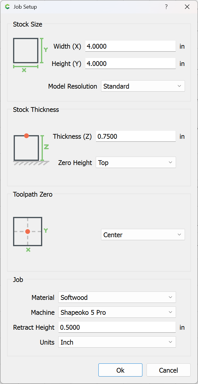
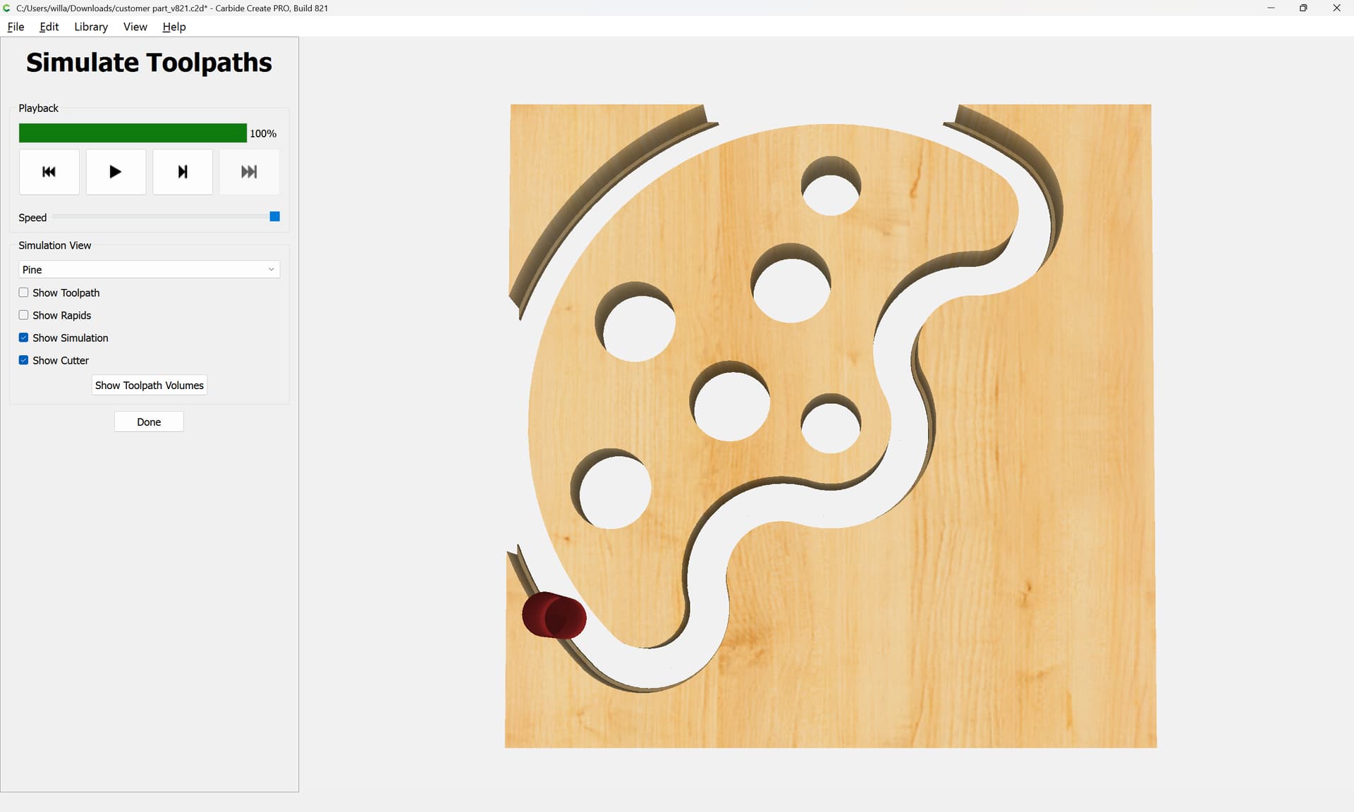
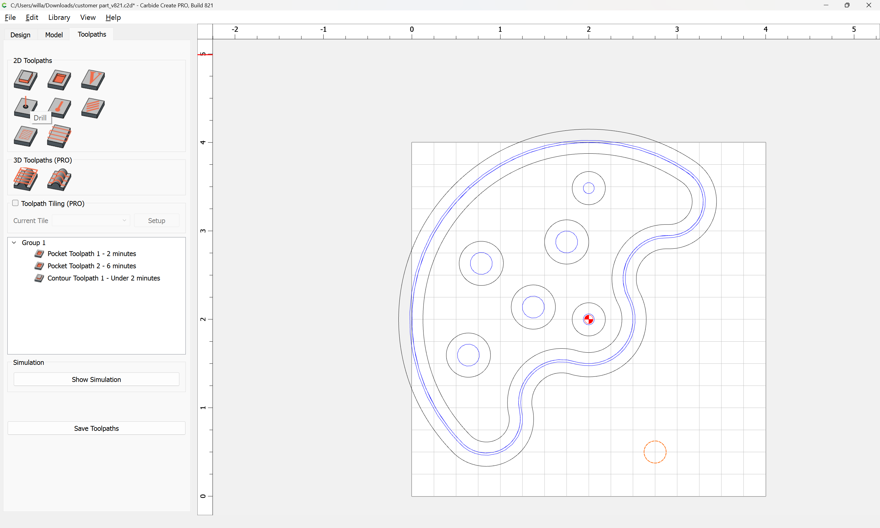
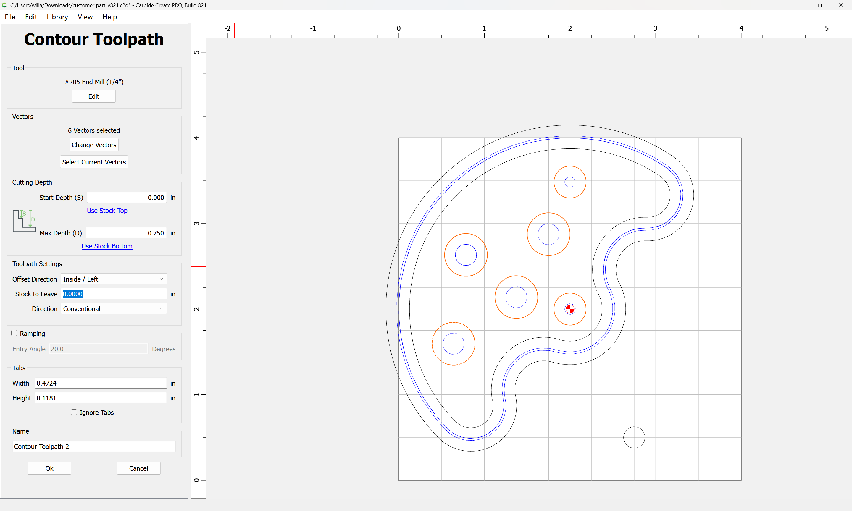
To finish this in Carbide Create, set the Job Setup to the correct dimensions:
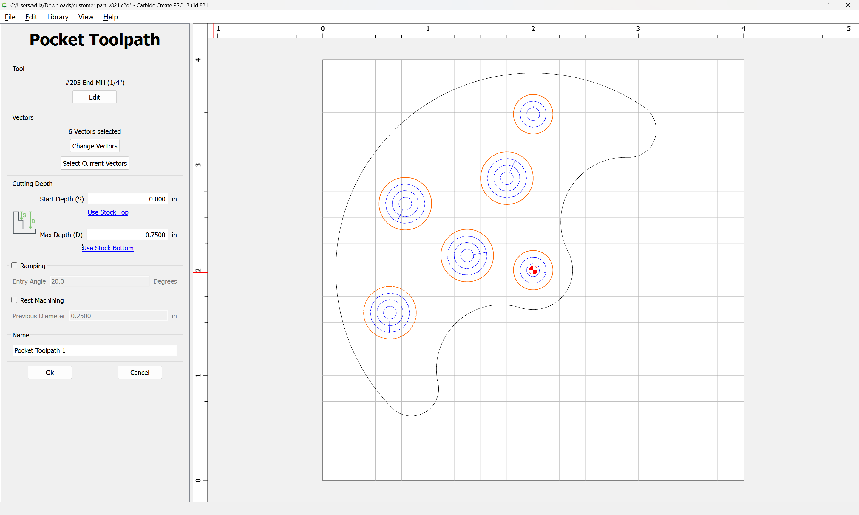
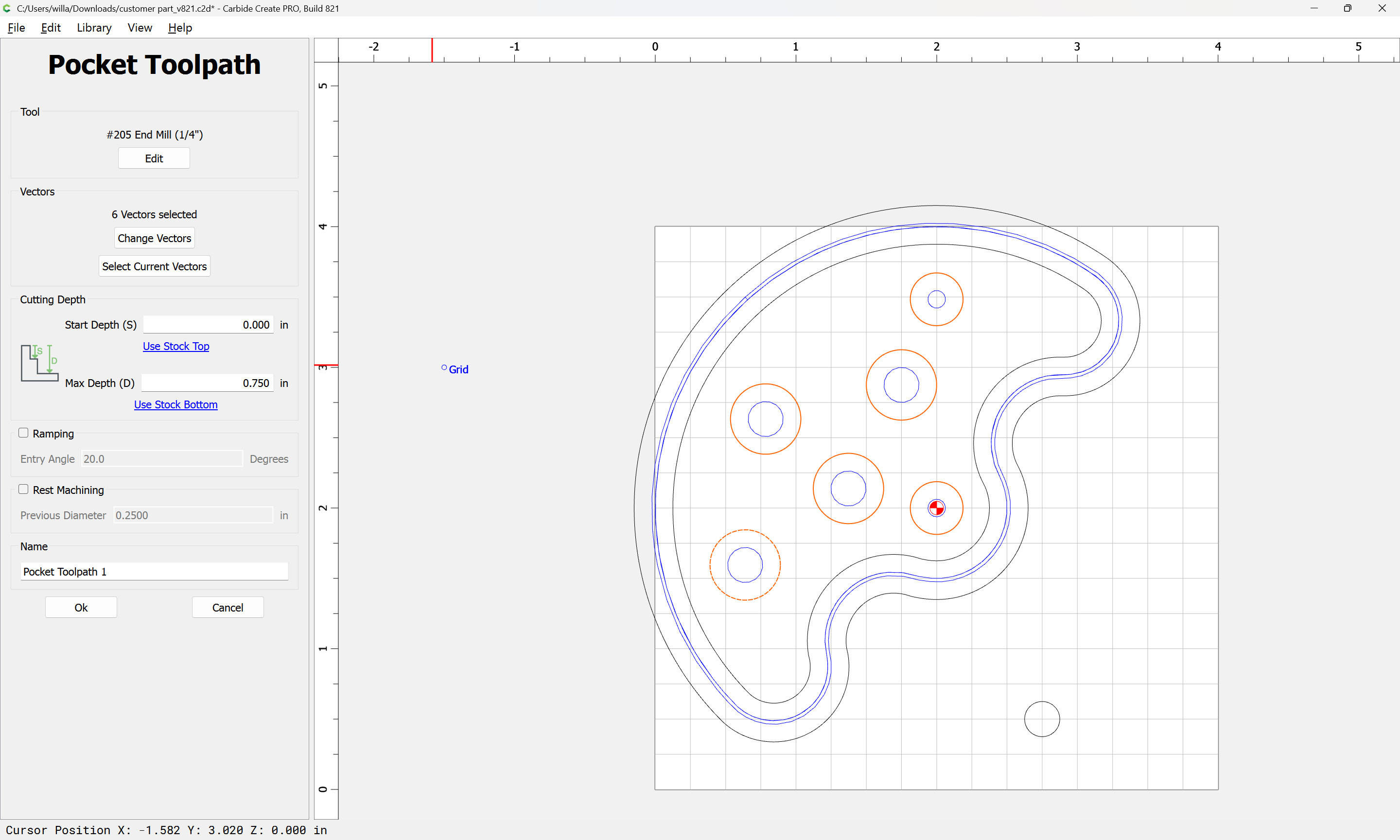
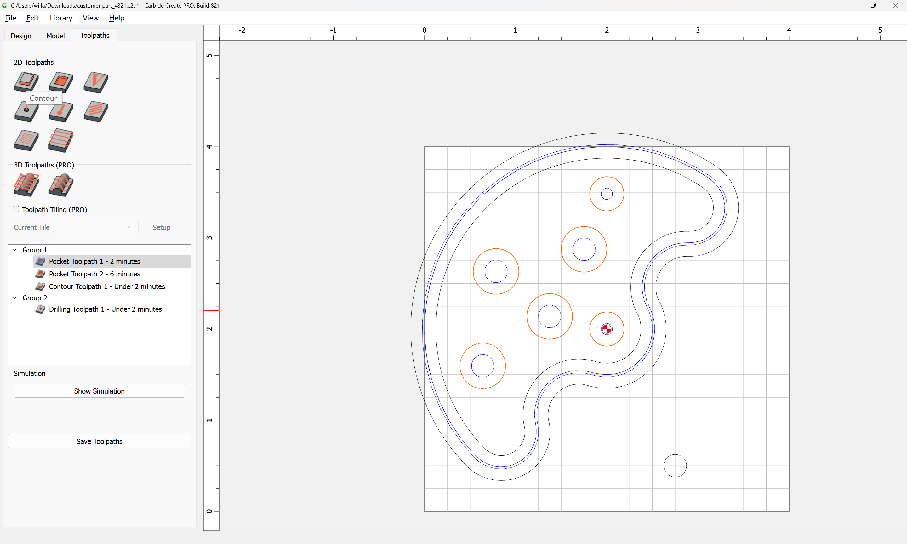
Then assign toolpaths — first a pocket:
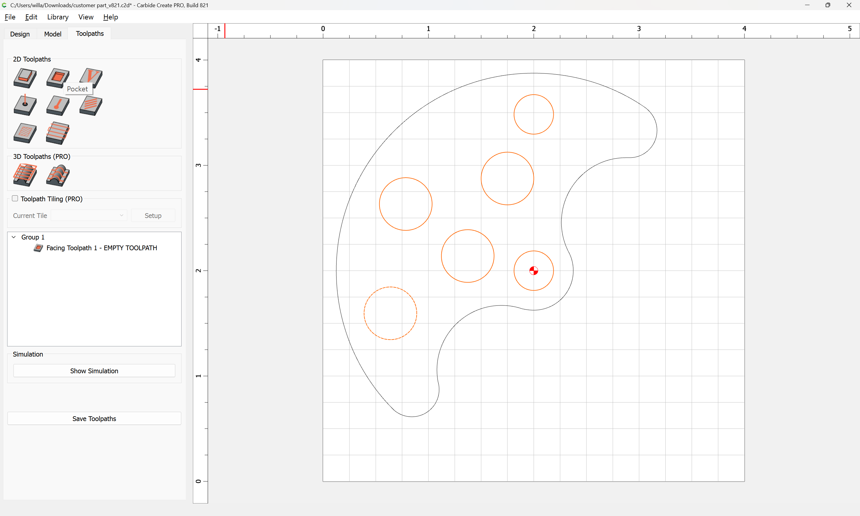
to the interior elements using a suitable tool — note that you will want a tool w/ at least an 0.75" cutting flute length:
For the perimeter, you will want to go back to the Design tab and Offset:
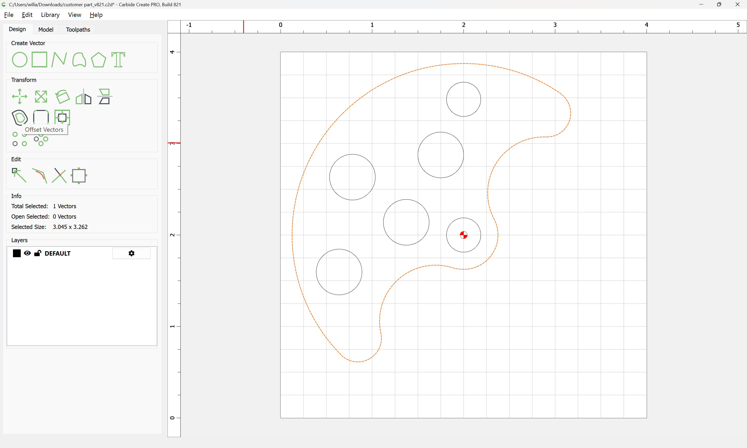
by endmill diameter plus 10%:
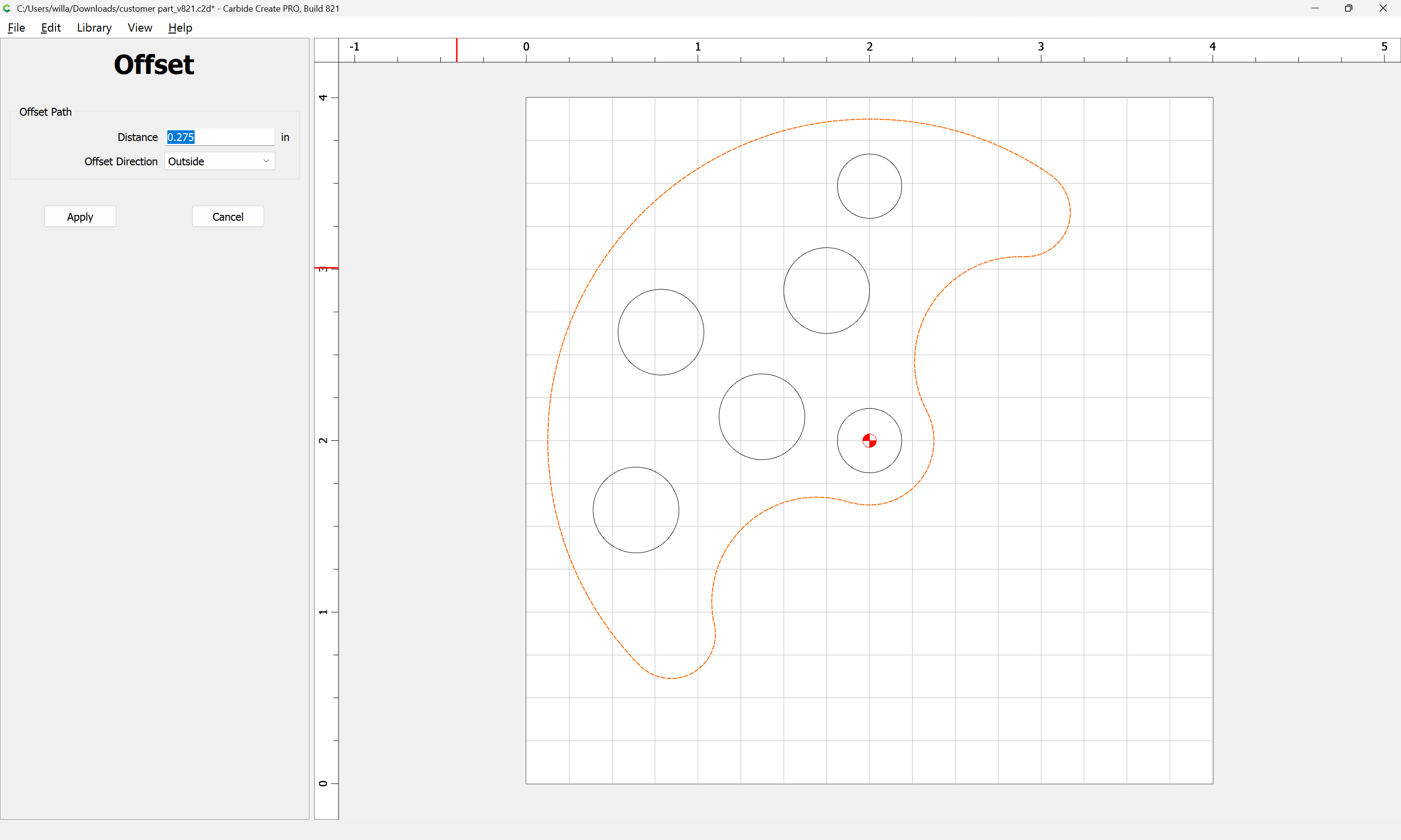
Apply
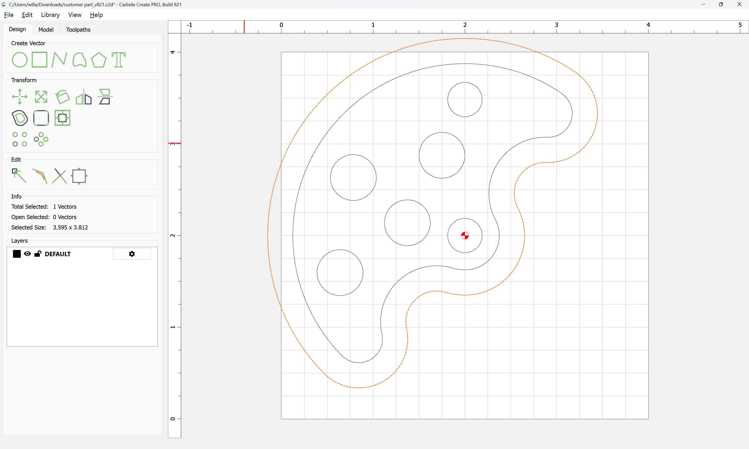
Then shift-click on the original geometry and add it to the selection:

and assign a Pocket toolpath down to tab height:

Then select only the original geometry and assign an Outside Contour toolpath to cut through the stock:
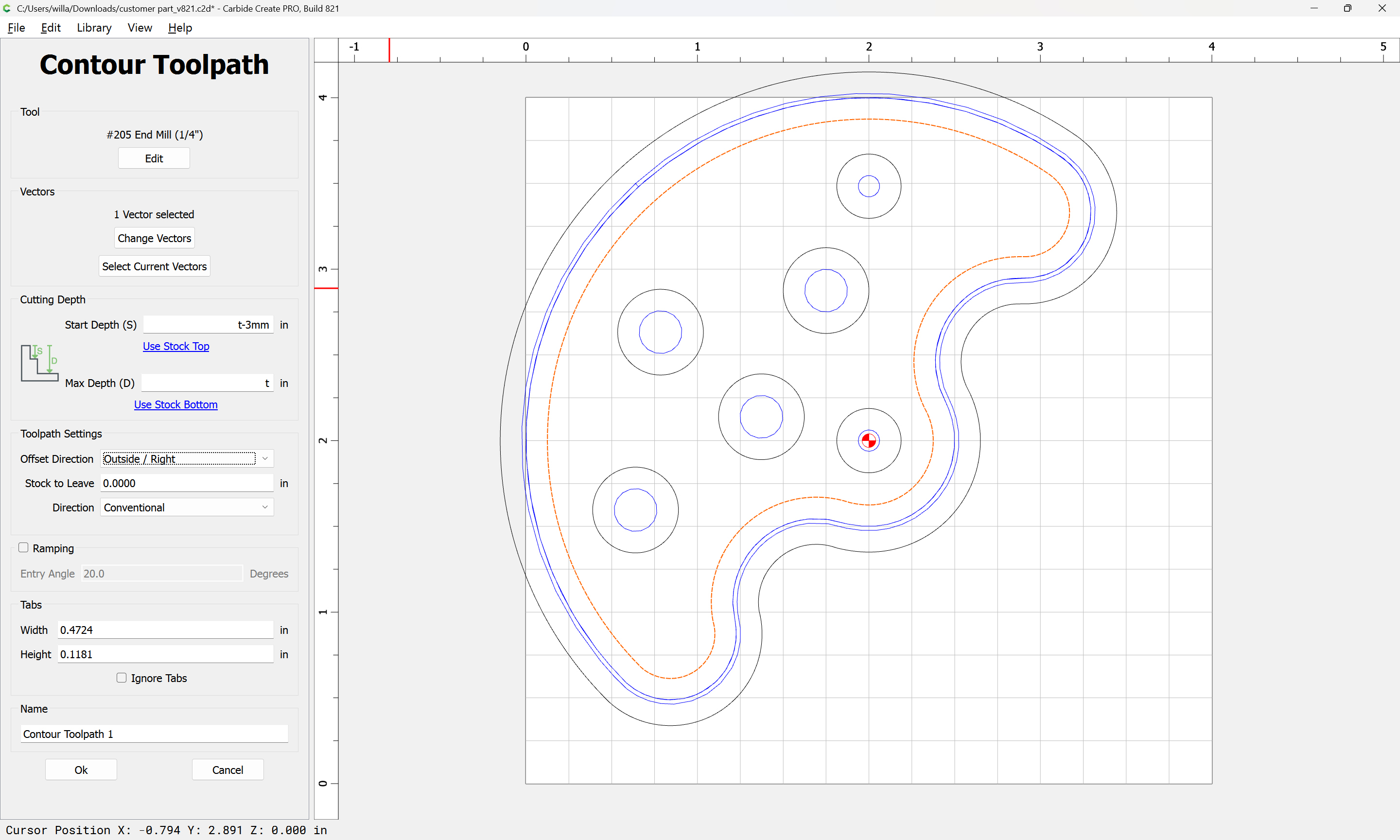
If workholding is such that tabs are needed, go back to the Design tab and add them.
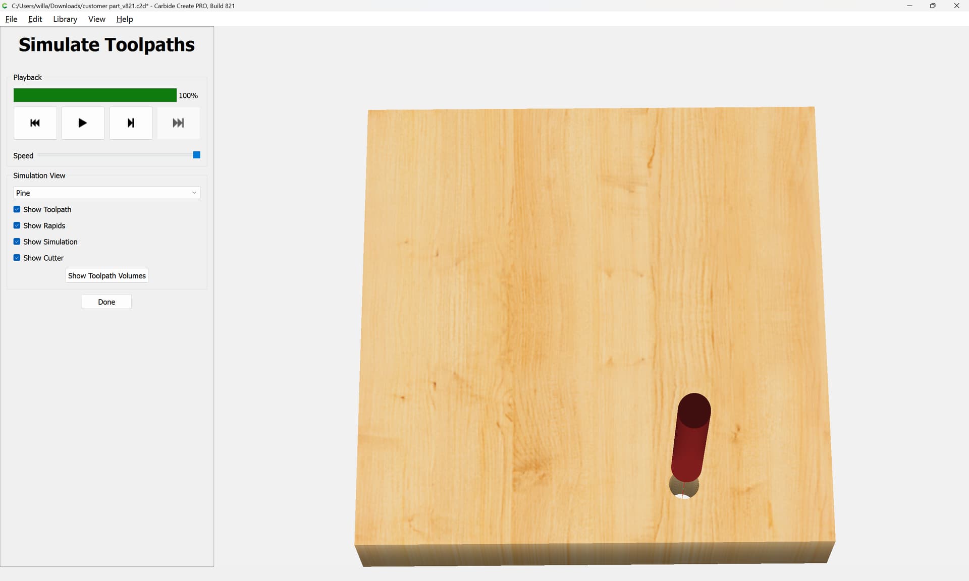
The preview without tabs:
Note that if an STL is exported, Carbide Create Pro or some other 3D CAM program such as MeshCAM will be needed. If a DXF is exported, then a 2.5D CAM tool such as Carbide Create may be used.
2 Likes
I have the Shaper Trace. Anything that is printed on a 8.5 x 11 sheet of paper comes in great. I use it if someone wants to sign a piece that I am carving. Maybe I want to duplicate a logo. The thing about this is comes in exactly to scale. I have found it very handy. As I recall it cost $99.
Douglas
1 Like
For the 2D part shown, the DXF export will do the trick. No need for a 3D STL file.
2 Likes
Here is a link to the whirligig type planes I’ve created on my shapeoko with Carbide Create and V-Carve.
4 Likes
To be clear: If I draw a 2D part in SketchUp and save it as a .dxf (there is a 2D and 3D option, which?) I can load it directly into Carbide Create, make the Toolpaths, and press GO?
Also, can I assume that holes are made with Endmills? If I need a ¼” hole, is it made with a ¼” endmill? Is it done in steps or just plunged through? Also, how fine of control can I get on a hole? In other words, if my part needs a 9/32” hole, will it actually be 9/32” or will it be something close to that?
I apologize for all the questions, I am totally new to this and need a little knowledge before I make the plunge.
Yes, that should work.
2D DXF is what is expected to be imported — 3D will import, but will discard 3D information.
Note that you will need to structure the drawing in Sketchup, and the export options for DXF in Sketchup so as to arrive at a workable file — if you have problems, upload a screengrab of the Sketchup design, a screengrab showing the export options, and the DXF which was made and we will do our best to look into it with you.
There are two approaches for making holes:
- a “Drill” toolpath — this requires a tool which will cut the desired hole dimension, and is vulnerable to issues of tool/machine deflection:
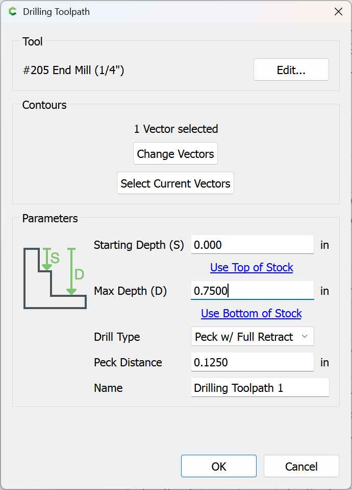
- a “Pocket” toolpath as was shown above:
Select round geometry:
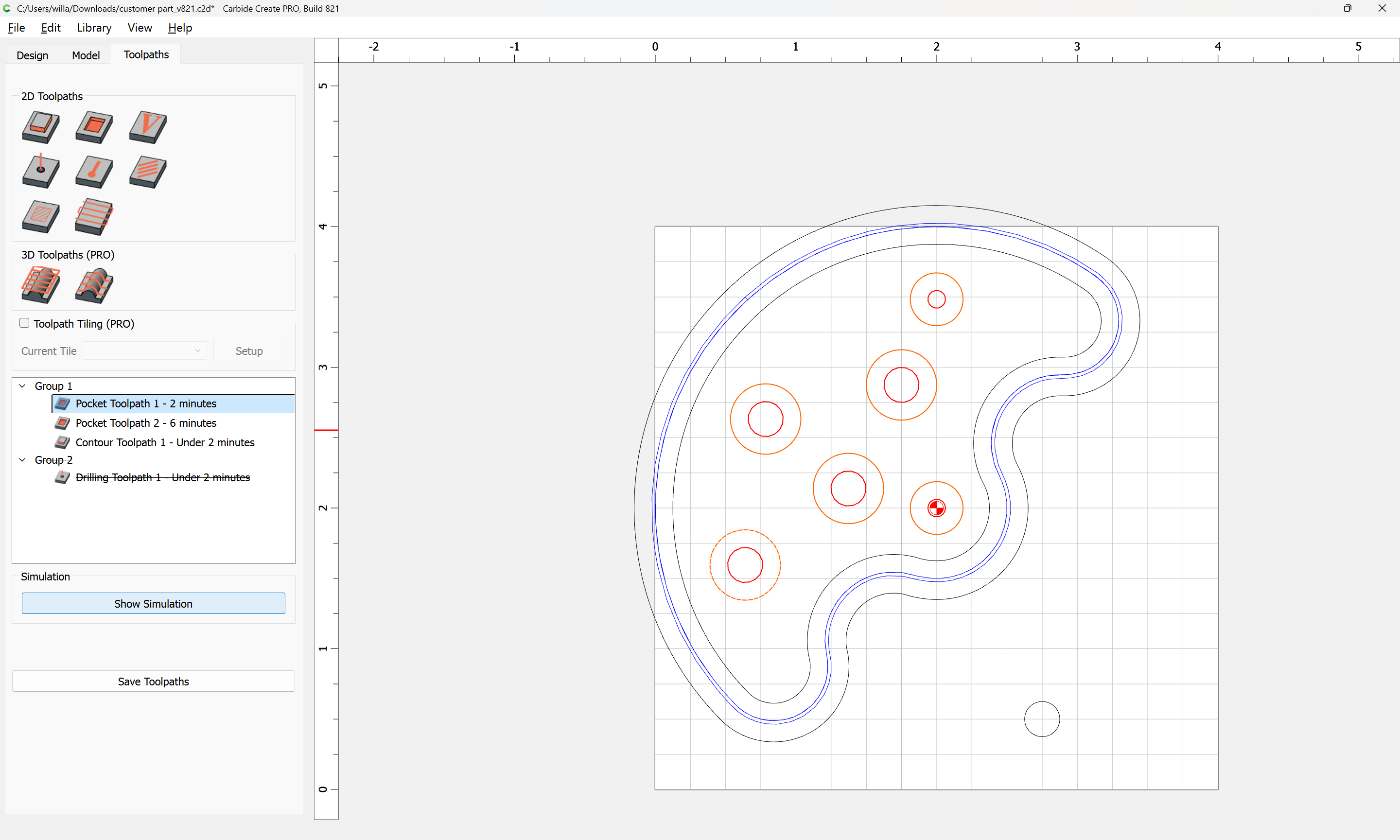
assign a Pocket toolpath:
Note that this allows the option of drawing the hole smaller, cutting it, doing a test fit, then adjusting the size and re-running the toolpath.
Alternately, if you have Carbide Create Pro, then if the hole is smaller than twice the endmill diameter you can use an Inside Contour toolpath
and adjust the “Stock to Leave” parameter:
and then make the cut and do a test fit as described above.
Alternately, this can be used so as to allow a full-depth finishing pass as discussed in:
and/or
and consider leaving a roughing clearance and taking a finishing pass.
For more on this see:
I drew a couple quick 2D parts in the SketchUp free version. I then realized they must be exported to .dxf format. And that feature is only available on the paid version. Looks like I’ll be forced to learn Carbide Create. I’m 73 years old and I just want to build things, not learn another software package.
Yes it will work using a 2D DXF file from SketchUp to whatever CAM application you are using.
Plug it in and GO, not quite that easy to make a perfect part.
It’s kinda like jumping in a race car. It may get around the track ( or not ), but finding the balance so it handles as expected and goes fast is the art form.
Given the products you have made, you have developed a “feel” for your existing tools and the materials you are cutting. That “feel” needs to be developed when using a CNC machine.
Materials - I would assume you are way past me in handling various types of woods.
Cutting with or across the grain presents it’s own challenges as you know. No different in CNC, but you can’t feel the resistance that you get when manually cutting, you have use your ears and eyes.
Fixtures - How not to wear a part. Cutting wood is a lot less force/energy than cutting metal ( another world as far as I am concerned ), but you can see get hurt.
We all make a lot of firewood when the part comes loose or an errant tool path is used.
I use painters tape on the part and table and CA glue between the tape strips. It works well unless you have a strong “up” force ( caused by an up cut end mill ) that grabbed the material.
I do not have a hobby vice as yet. You can use the plastic Crush It clamps secure the part if you tool path does not run it over. The plastic clamps can take a beating.
Data import - You need to confirm the unit of measure is correct so your scale of part is correct.
You should confirm that Arc’s in the CAD data transferred to the CAM application. The idea to to maintain as much accuracy as possilble. Sometimes entities are “stroked” ( meaning a lot of short line segments ) which is not fatal, it just means additional scaling or manipulation maybe limited.
Tool Path generation - I am assuming your are using a hand held router at times, so you know about keeping the tool bit center offset (at least 1/2 dia of the bit) away from the actual part edge.
You must have felt/heard the effects of “slotting” when doing this. Slotting means the bit is cutting on both sides, we try to avoid this when you can. The suggested process is to create a “pocket” that is bigger that the tool, so when you are cutting at the part edge, you are cutting only on one side of the tool bit.
In your example a Contour for the outside profile and Pockets for the holes would be what I would do. If your material is thick ( again a feel ) a Pocket for the outside edge would be appropriate. Drilling holes does not produce accurate holes, you are better off “circle milling” ( a Pocket ) inside the hole with a tool bit smaller than the part hole.
I am going to stop here, because there is probably too much BS I just spewed, that someone else will clarify .
It will work very nicely, once the “feel” is engrained.
Do it !!
Jim
Carbide Create is much simpler than Sketchup, but the same principles will apply/ be used. I believe it will still be helpful to plan out in 3D in it, then recreate parts in Carbide Create for cutting.
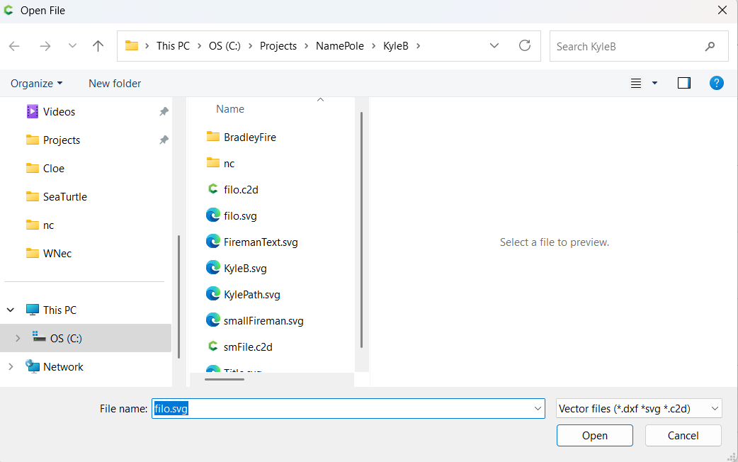
Note that for arcs in DXFs, it will be necessary to use a third software application to import the DXF, then export as an SVG (which will preserve the arcs as curves), then import the SVG into Carbide Create.
If the free STL export from Sketchup is an option, then any 3D CAM tool will work (MeshCAM is about the easiest).
Let us know if you need assistance with any aspect of Carbide Create.
Based on your recommendation in another thread, Will, I am successfully using the free/open source LibreCAD to resave the DXF’s I output from VersaCad, as SVG’s.
2 Likes
@nukebert - Based the the previous thread, it seems that Carbide Create will interpret a DXF files Arc and generate a series of “strokes” that represent the Arc. It works, just not optimum.
If you can export an SVG file, the results in Carbide Create will translate correctly.
I did not know that. Good day, learned something.
You can review the node point coordinates in Carbide Create ( CC ) I believe.