I do not own a CNC but am considering one for use in building my models. All of my models originate as a drawing from a book or a set of plans. My question is: do all of those parts have to be redrawn in a software app?
Does anyone else use a CNC to build models?
Please, any advice would be greatly appreciated.
2 Likes
answer to the question: yes.
There is software that import pixel images, and trace them. Inkscape is a open source example, the tracing part is mediocre, Gimp can do that too, but needs more exercise before one can get nice results, but CC is 1. free,and the tracing part is superb! Recommend to try that. It is little hidden under Import, the second from left. There also are some really good tutorials available in this forum. GL!
2 Likes
![]()
I’d guess the quickest way to get your designs into the computer would be with scanning them on a flatbed and doing some kind of tracing to produce an SVG.
It really just depends on the kinds of models you’re making and the complexity of the drawings. Your standard flat panel should be pretty quick to import.
And you can always practice the digital workflow before committing to a machine to see if it’s for you ![]()
2 Likes
Yes.
For a model adjacent part see:
which is probably the most extreme case.
Also see:
2 Likes
Only the parts you want to cut on the CNC. If you have a part that can be easily cut on a jigsaw, scroll saw, table saw et.al… You can just draw up the details you need to machine. You just need an accurate way to position those details on the workpiece.
What type of models?
1 Like
Yes, I understand the part about not all parts. I have been building models for over 20 years using normal shop tools but not a CNC. My models are usually vehicles and 300-400 pieces. I apologize for not being clear. If I determine that a part or parts would best be made on a CNC, do I have to draw the part in the respective CAD/CAM software? Someone suggested using the TRACE function. Thank you. I tried that and it seems to work but am I losing accuracy? I guess that depends on me. I would like a recommendation from someone that builds models. Does it make your model building easier? I spend up to 500 hours building a model (over 900 on my S.G. DeVries BIG Crane) and there are no plans to ever sell any, so I don’t want it to make money.
Those must be some serious vehicles.
You need to decide what level of accuracy your models require. Be reasonable.
As you know wood has a personality and there are practical limits.
Design:
You need to decide what models are 2D or 3D.
The “smarter” the modeler/mathematics, the better results in quality of data.
3D
A true CAD system ( meaning not a mesh model ) is the best option
A mesh modeler will work, but watch the tessellation to determine if the triangle approximation falls within your accuracy requirements
An image based modeler will need a higher effective resolution ( larger dimensions are more affected ).
2D
Again a CAD system is the best.
Arc’s are the key, if they are “stroked”, then you lost the arc definition and scaling becomes an issue.
A paper world system like Inkscape can be accurate enough and still have arcs.
A trace process is an interpretation of a pixel rendering of the original intent.
This may fall within your tolerances, but it is risky at times.
Using the original source data as the basis for path generation is the purest/cleanest form of data you can make.
1 Like
Can you share an image that needs to be traced so we can see the detail and image quality?
1 Like
If you have access to Instagram, some of my models are under my user name ‘nukebert’. There’s not a lot, I’m slow.
1 Like
In order to use a CNC, one pretty much has to have G-code to cause the machine to move/cut, absent specialty approaches using computer vision/AI — there are a couple of ways to arrive at this:
- draw in 2D/apply 2.5D toolpaths — note that some toolpaths such as V carving and Texture will result in a 3D cut/appearance and with a bit of imagination and planning one can create parts with a great degree of verisimilitude — note that this is simply a computerized version of the way in which you are current making parts using traditional tooling — it’s just that rather than doing a setup or making a jig/fixture you’re drawing geometry and associating one or more toolpaths. Carbide Create should allow one to work thus and we can support and assist you with this.
- model in 3D using a sculpting tool/apply 3D toolpaths — this allows one to make pretty much anything which one’s imagination can arrive at — if one is able to visualize the 3D model on the 2D screen and arrive at it using the software interface — the usual suspects here are Blender and Sculptris and there are some other folks who may be able to assist with this
- model in 3D using a traditional CAD program/apply 3D toolpaths — we sell Alibre Atom 3D for this:
which approach some folks are quite successful with, and which allows making pretty much anything, including sculptural designs so long as one can draw them/realize them in the interface.
A couple of other commercial programs to consider, and some commentary:
- Autodesk Fusion 360 — this was very popular when first made freely available with all features, but since then the “hobbyist” license has become quite limited and anything beyond it which is not a .edu license is very expensive. I mislike the company, the software, and the founder for reasons which need not be discussed. Watch videos on Youtube dating back to when it was free to get an idea of how one does things in it
- MoI, 3D modeling for designers and artists — one of the simplest and most straight-forward 3D CAD programs, the UI was created for tablet computers and would probably be a good fit for me and will probably be the next commercial program I try (I mostly use tablet PCs and rarely sit at a desk with a mouse which has been a big problem for my learning traditional 3D CAD such as Alibre)
- Plasticity — a fairly recent development, it is billed as “CAD for Artists” and tries to bring the simplicity and interactivity of Blender to traditional 3D CAD
There are also a couple of opensource programs to consider:
- FreeCAD: Your own 3D parametric modeler — exactly what it says on the tin, some folks who believe in opensource ideals are able to make it work and are quite successful with it, especially since the recent v1.0 update
- Dune 3D — a nascent development and only on v1.3 last I checked, this traditional 3D CAD tool was created by a programmer noted for making a popular PC Board design program who assembled a 3D CAD program out of a number of opensource components/code, which effort is best summed up by the developer’s footnote:
I ended up directly using solvespace’s solver instead of the suggested wrapper code since it didn’t expose all of the features I needed. I also had to patch the solver to make it sufficiently fast for the kinds of equations I was generating by symbolically solving equations where applicable.
which brings us to the last approach — programming — a quite different approach, it gained an elegant interface, “Grasshopper” in the venerable commercial program Rhinoceros 3D, and the poster child for it would arguably be:
Naturally, a programmatic approach results in many different programmers making many different tools, and a recent development, Python being added to OpenSCAD:
has me applying my own quite basic programming skill to work on:
hang on while I get logged into Instagram and see if I can find a part to draw up…
1 Like
Looking around a bit, the rims at:
https://www.instagram.com/p/CyMcn48rUKD/?utm_source=ig_web_copy_link&igsh=MzRlODBiNWFlZA==
are of course quite easily drawn up and cut as shown at:
If you’ll provide a drawing of a more complex part we can walk through making it in a couple of ways with you and you can determine what approach best suits how you wish to approach things.
1 Like
OK. This is a part as requested.
I looked at your Instagram post.
Freaking incredible work. You are a true toy master !
How comfortable are you with a CAD system ?
That part is 2D and can be drawn in any 2D system that supports tangent arcs.
You can export via DXF or SVG so long as the Arc’s do not get stroked to line segments.
Given what you have created without CNC, I am going to watch what this master does with a new implement of creation.
I will layout the part if you can provide dimensions.
It sounds like you are using someone else’s CNC, so let me know what format they prefer ( DF, SVG or IGES )
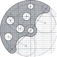
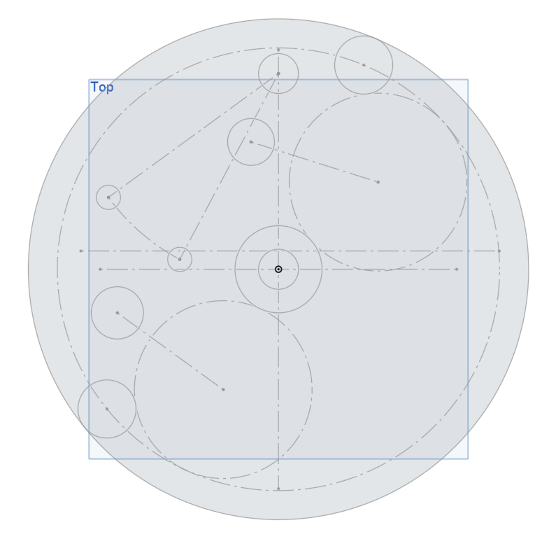
This is quite low resolution:
and I don’t see any dimensions.
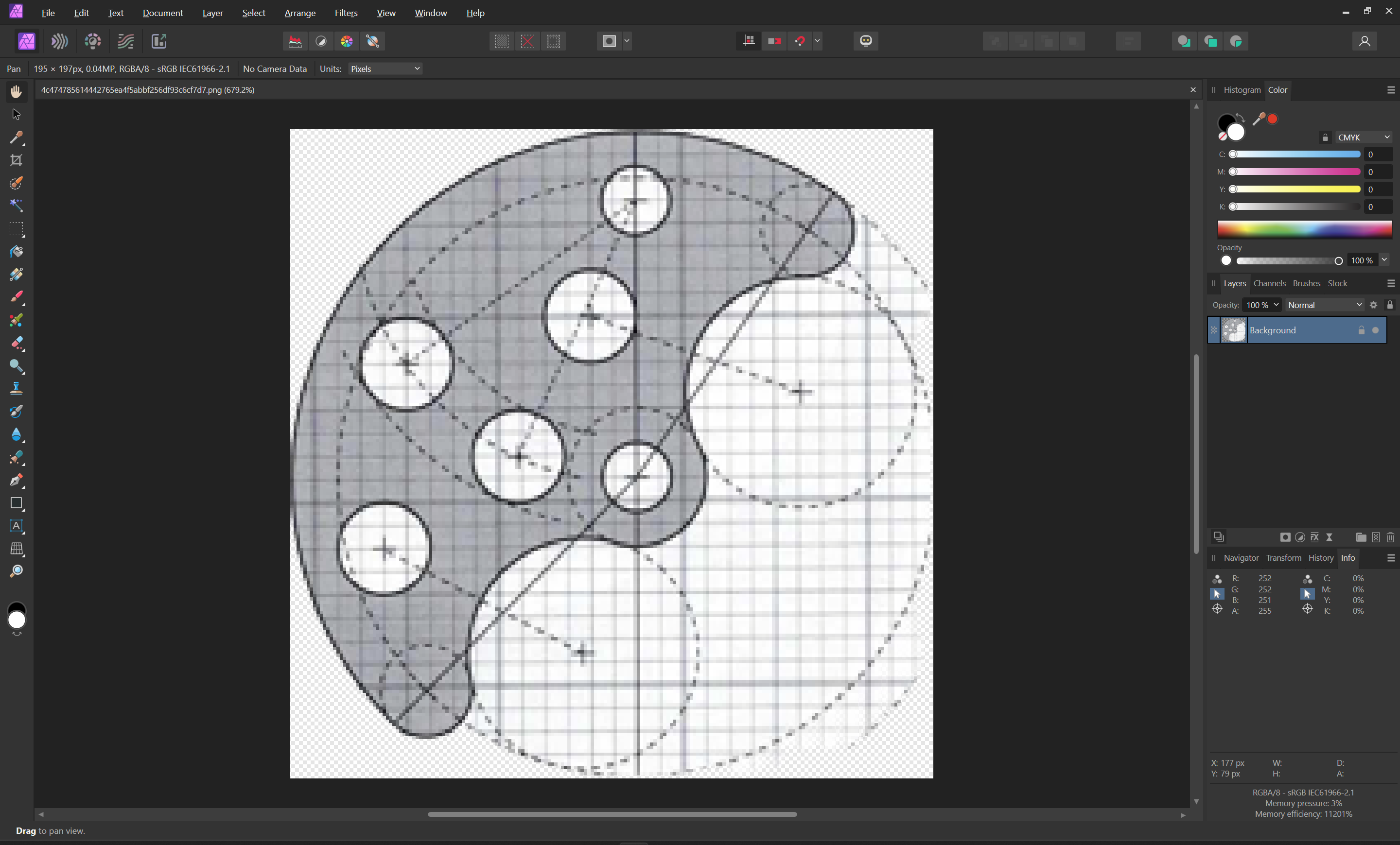
Assuming that the grid is 1" with 1/4" divisions…
(described at: Job Setup)
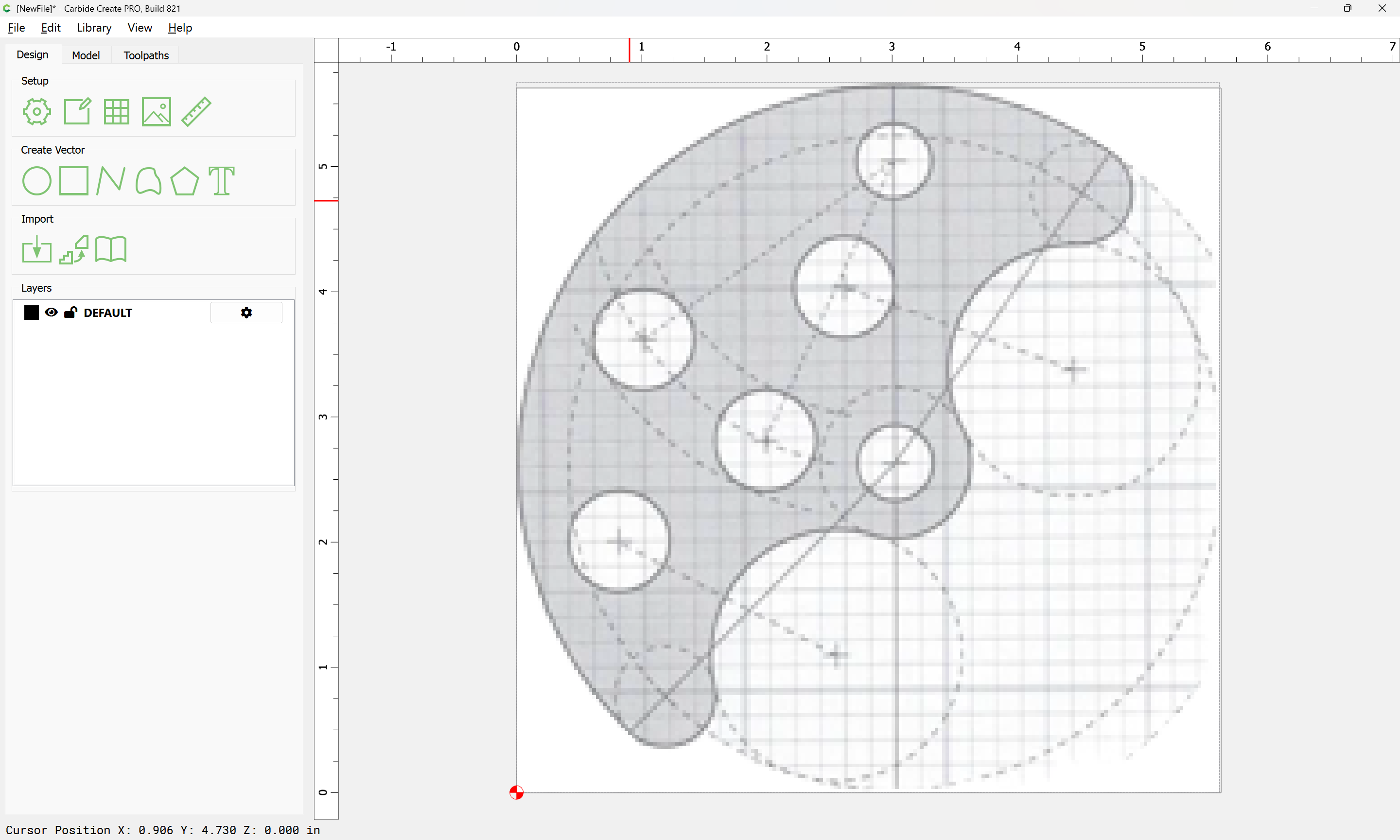
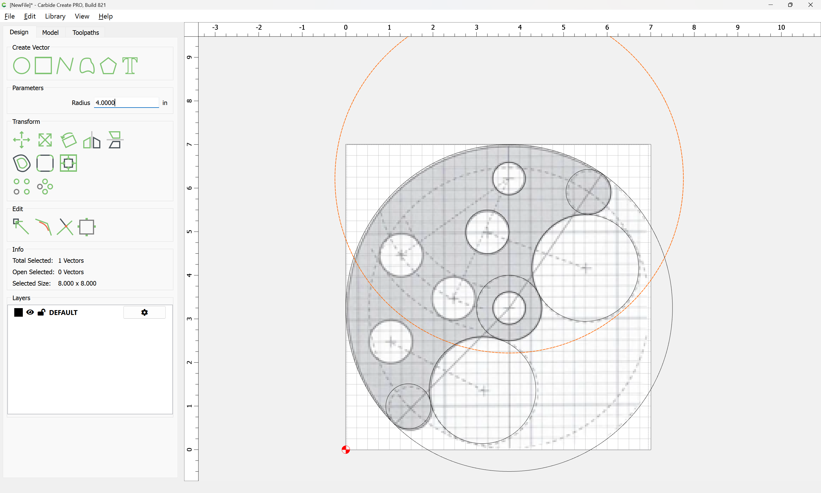
we import the pixel image as a background:

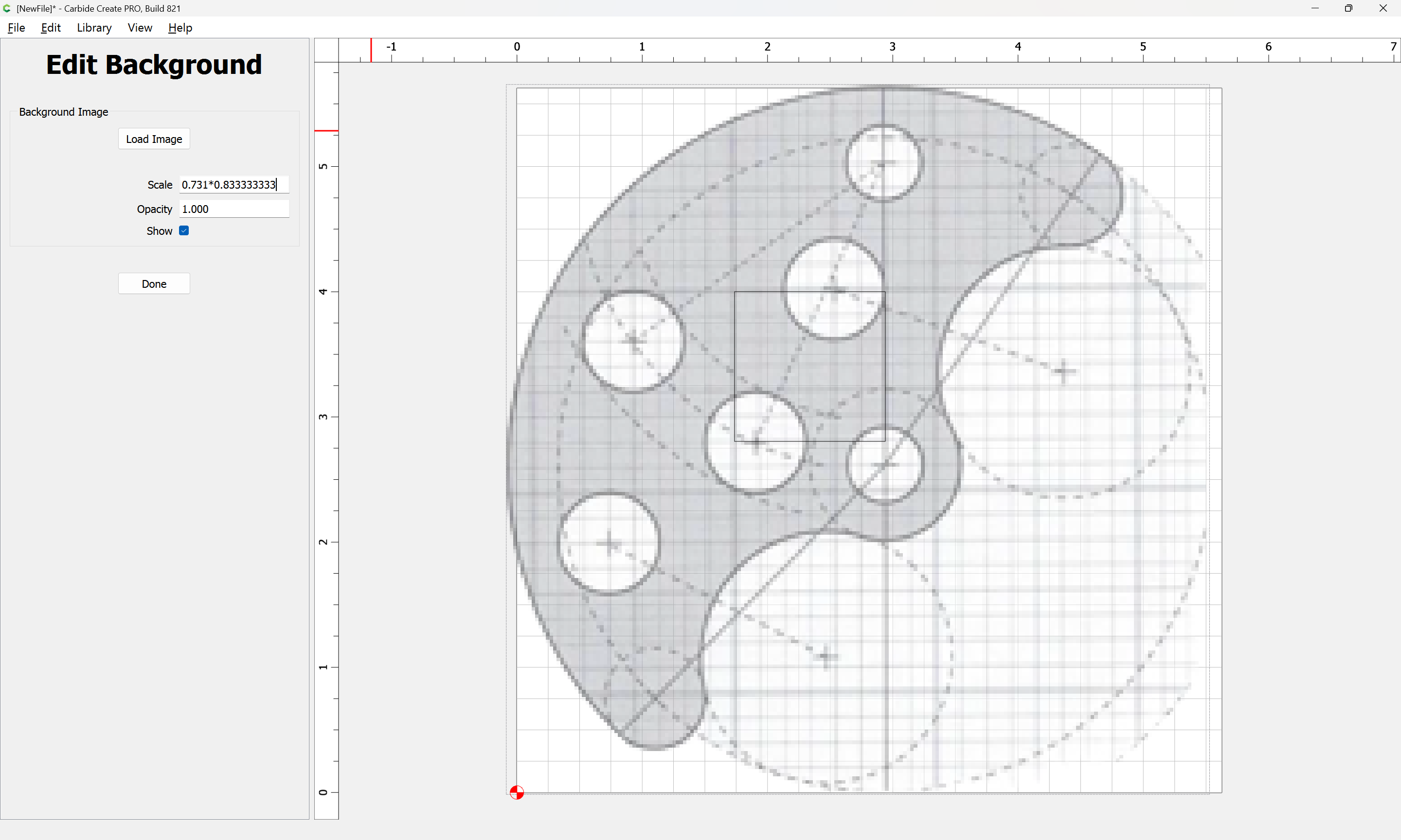
and adjust until the grid lines line up by drawing a square as large as possible:
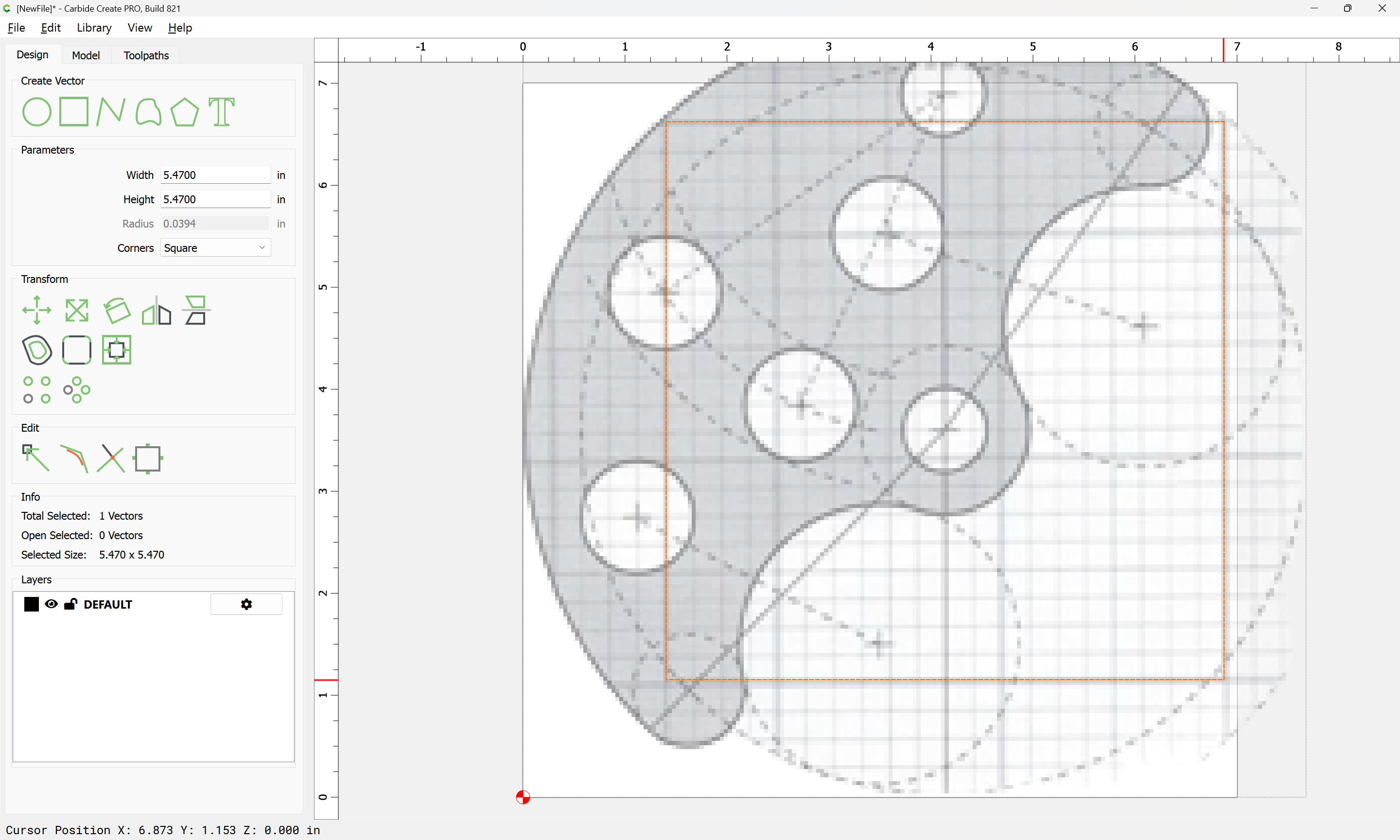
and determining the necessary scale:
4 / 5.47 = 0.731261426
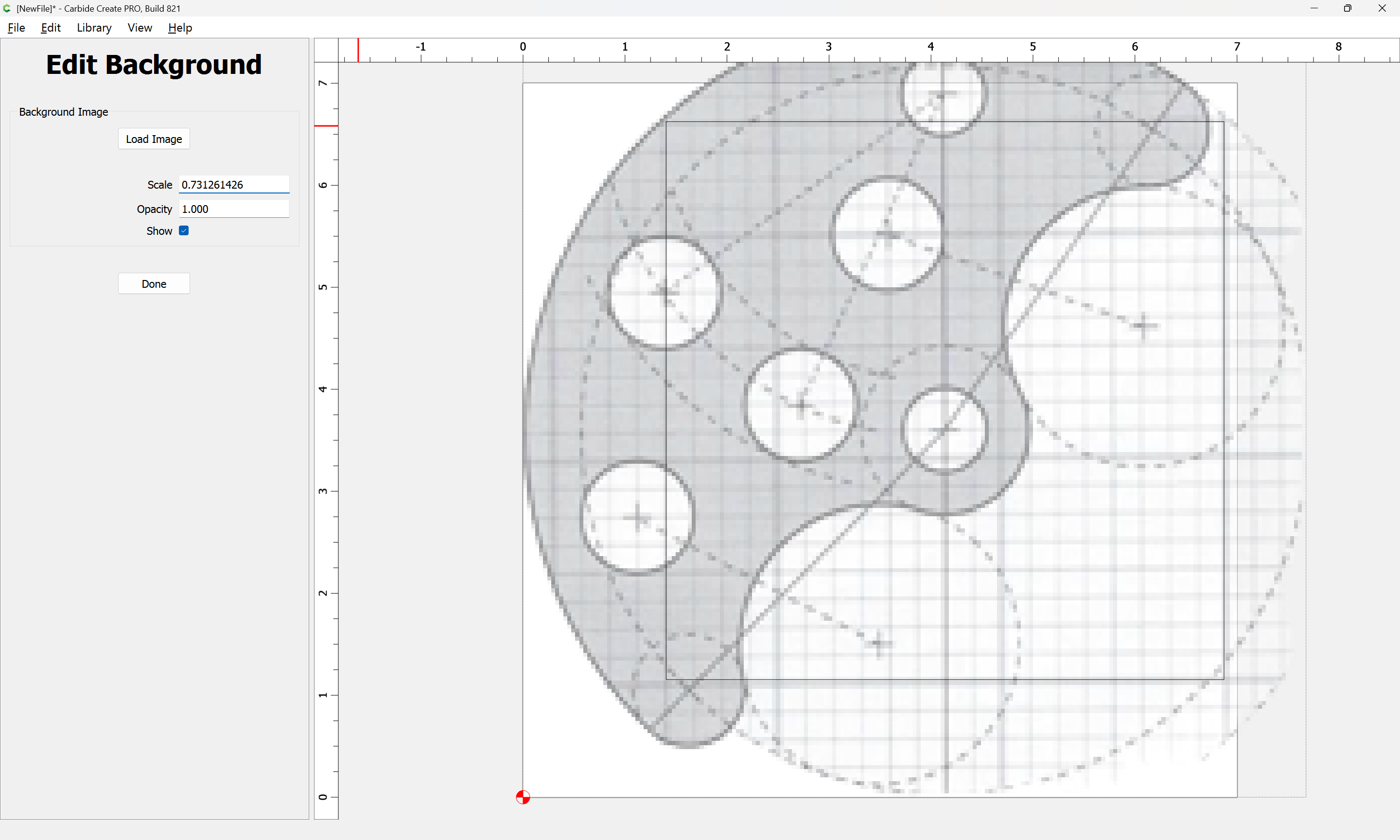
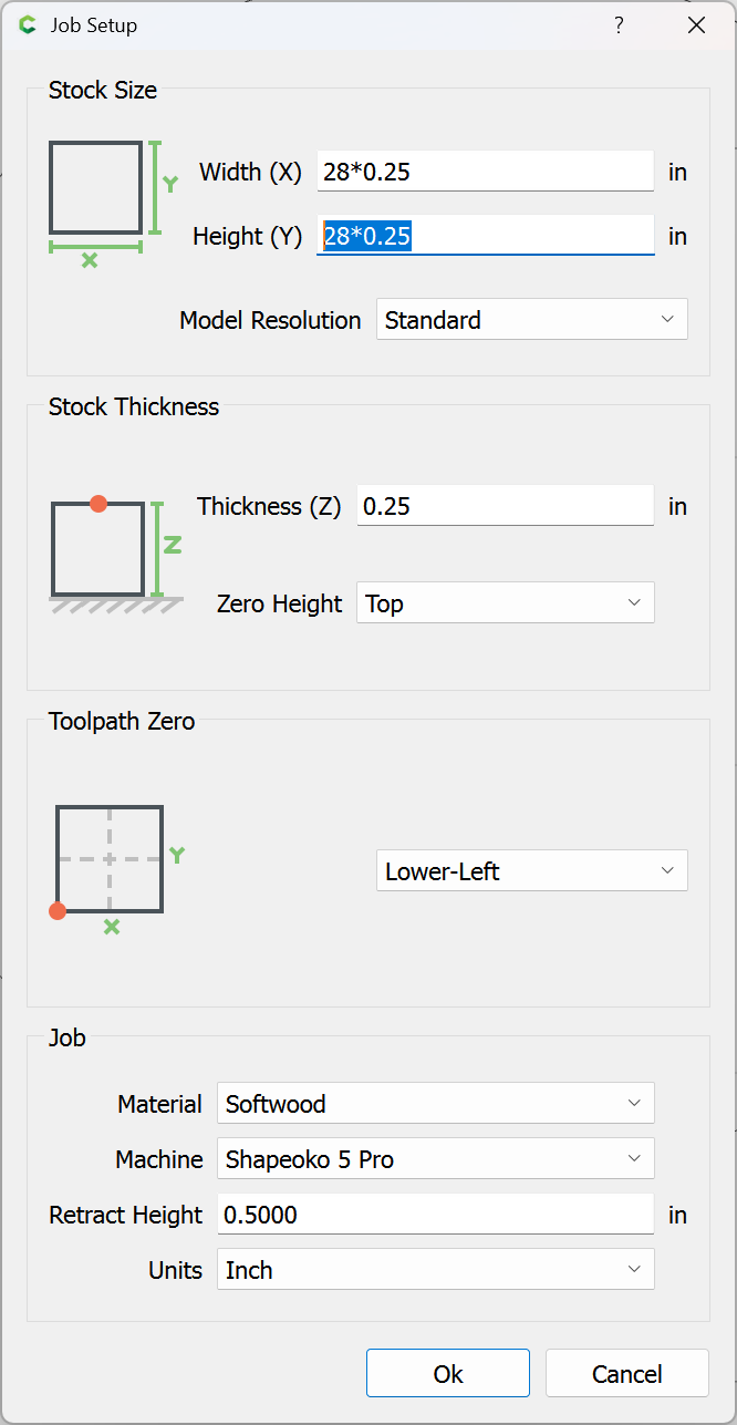
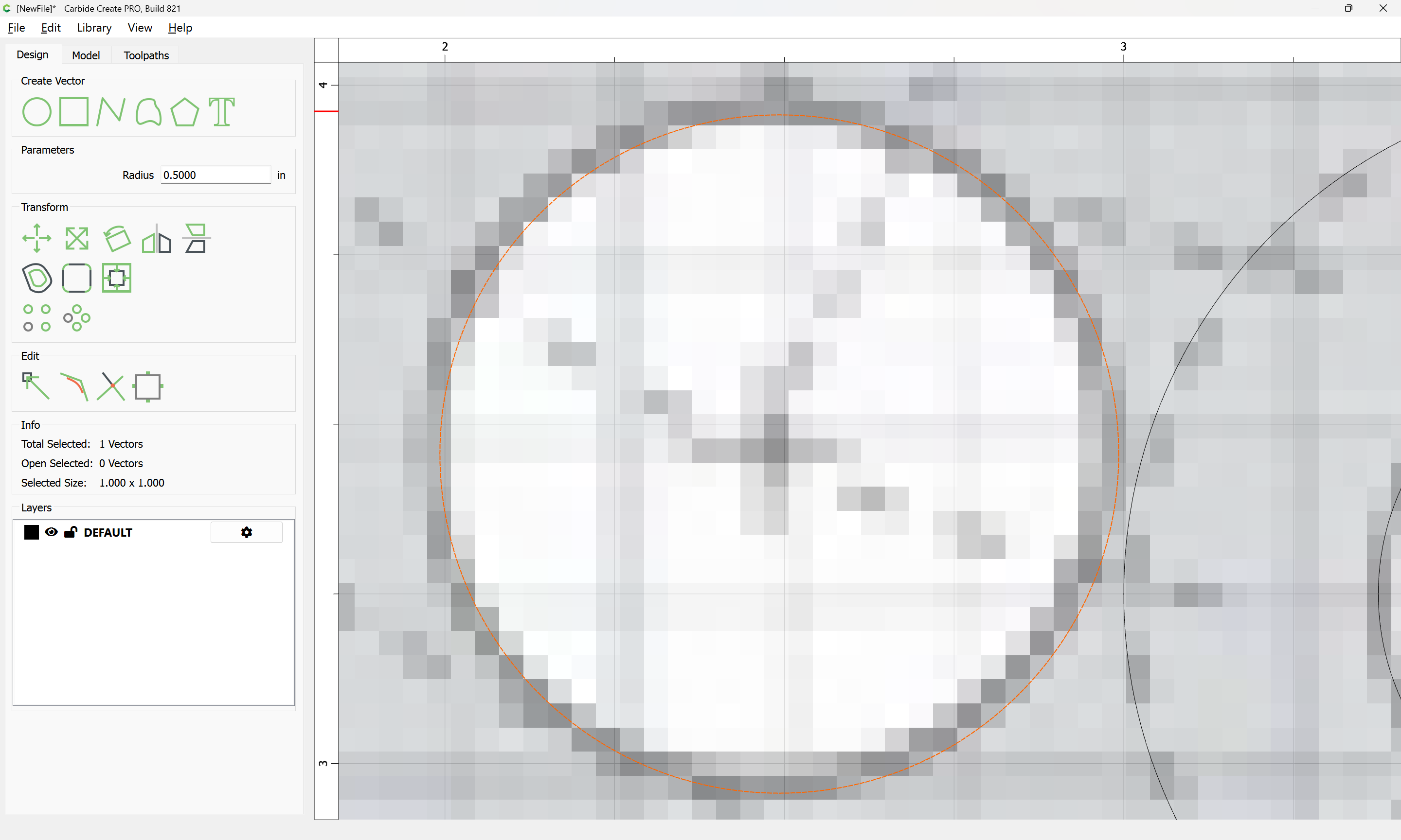
show the Grid:
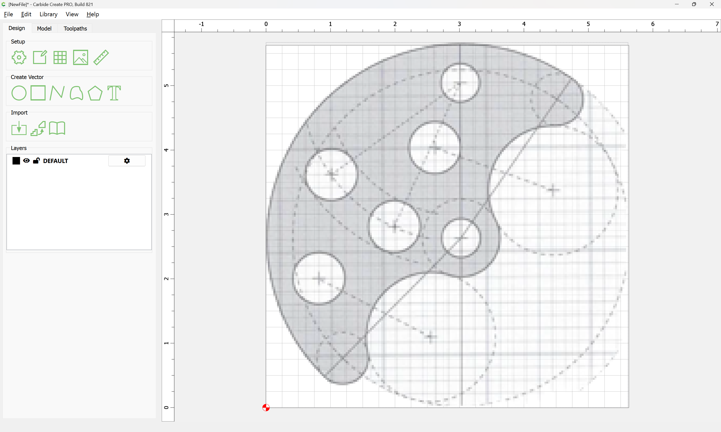
and drag things around until they line up and if need be adjust the scaling further:
After fiddling around for longer than I’d care to admit we arrive at:
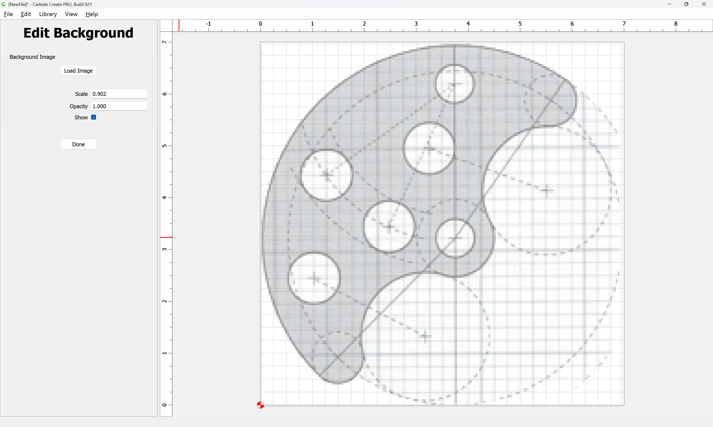
which seems workable…
1 Like
Here my contribution
I think it is geometrically constrained correctly, but I do not have dimensions.
1 Like
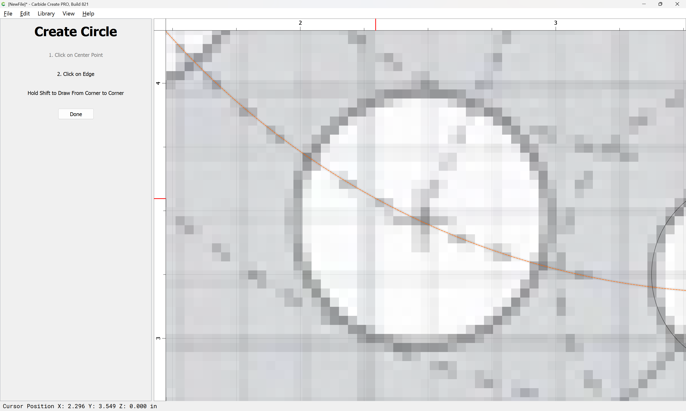
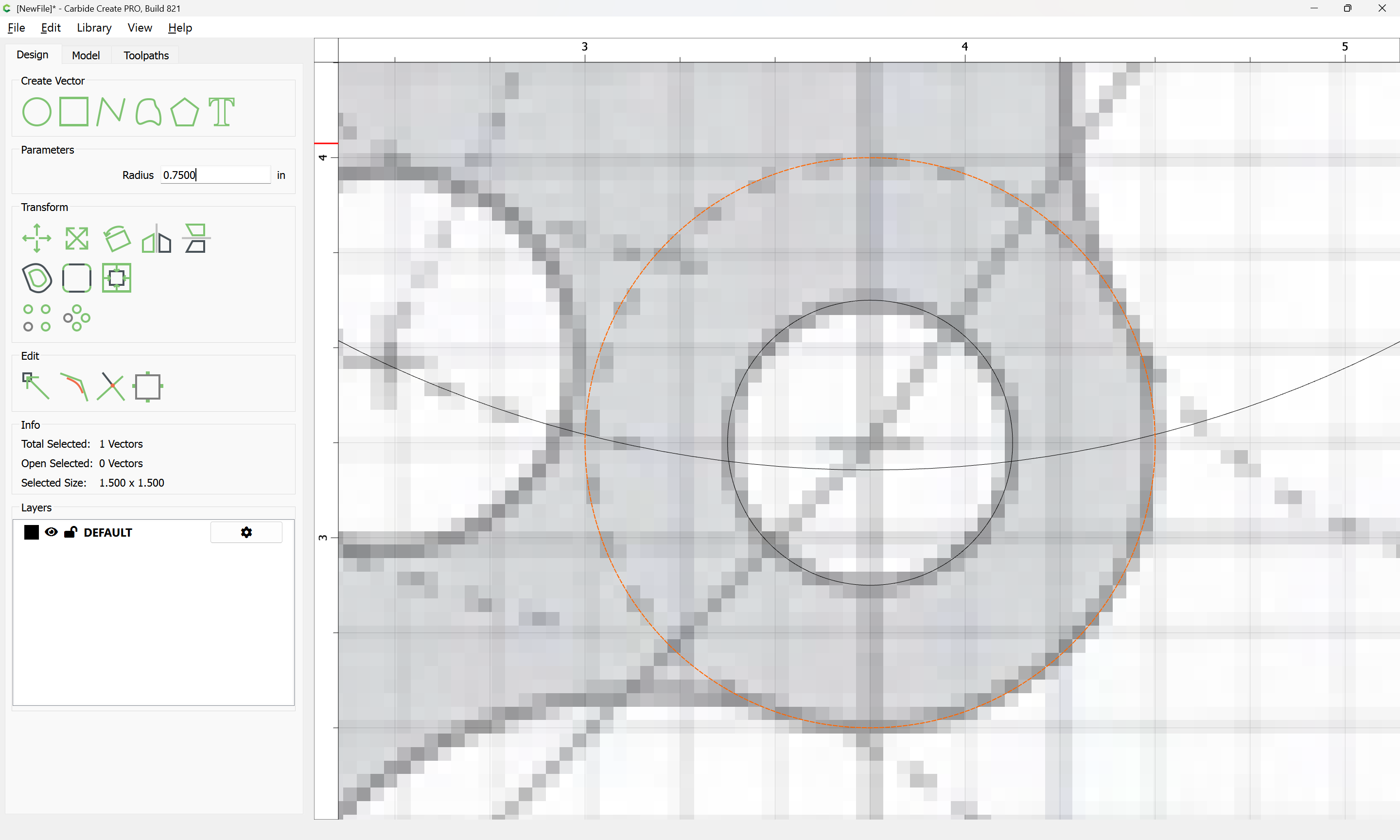
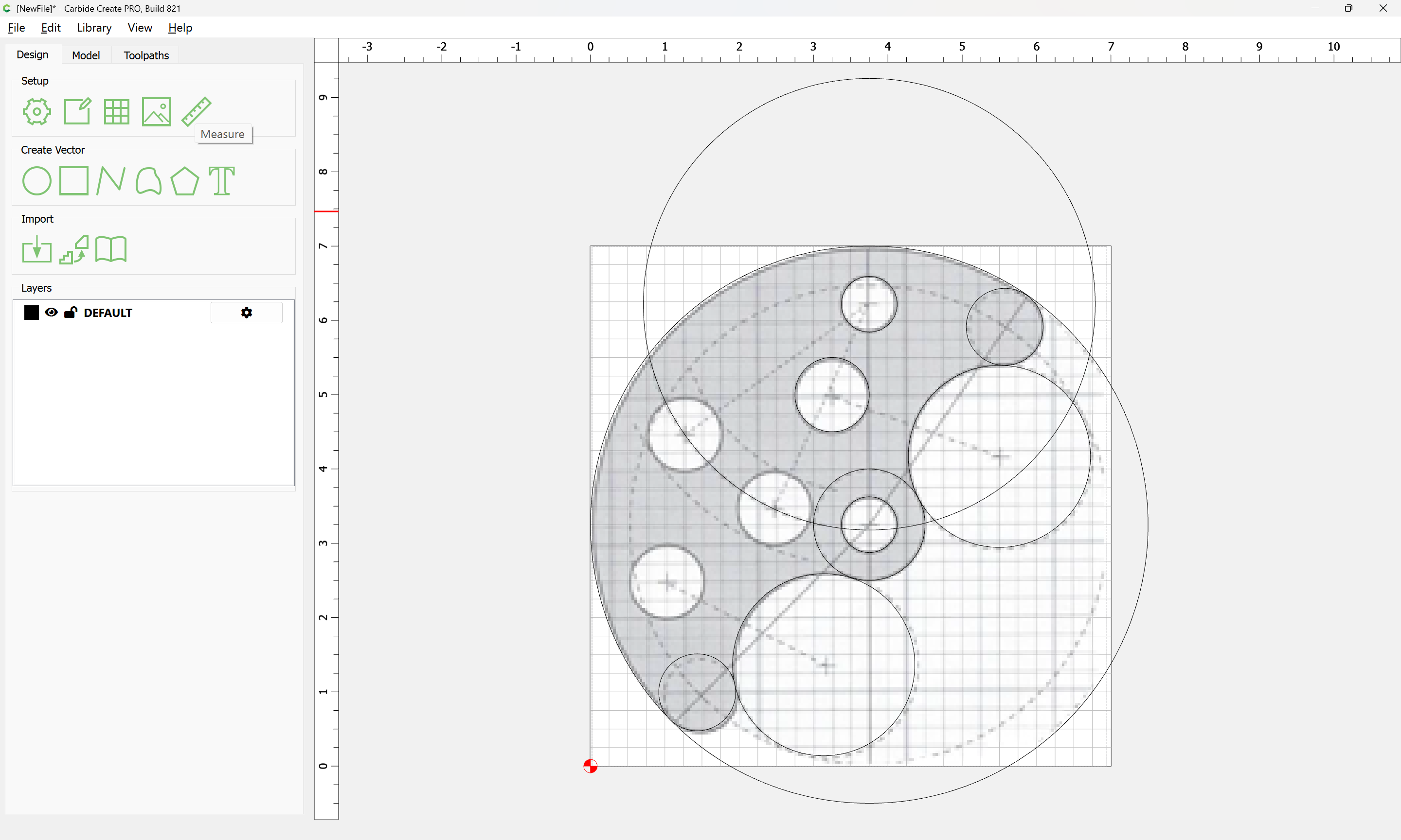
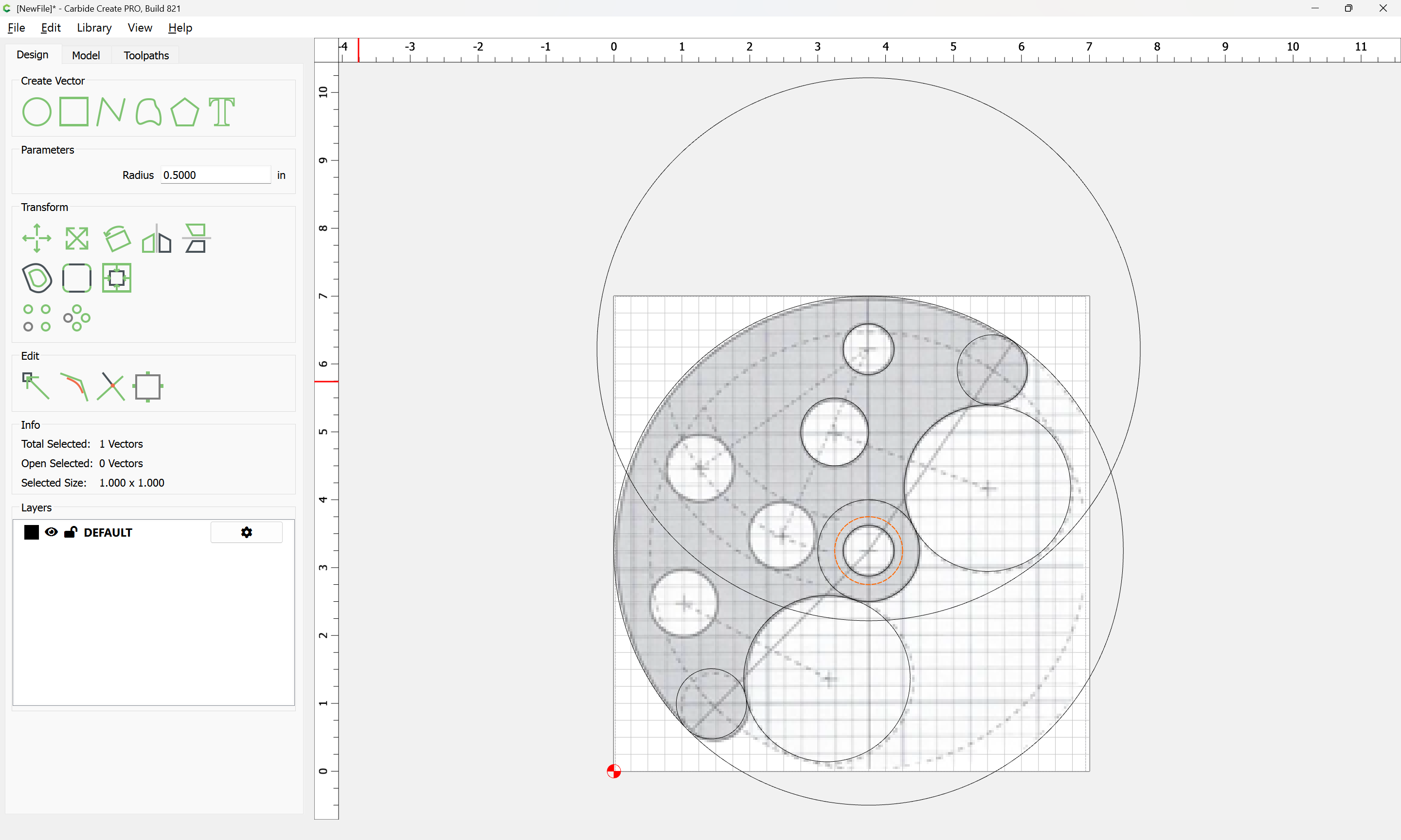
At this point, it’s “just” a matter of drawing circles:
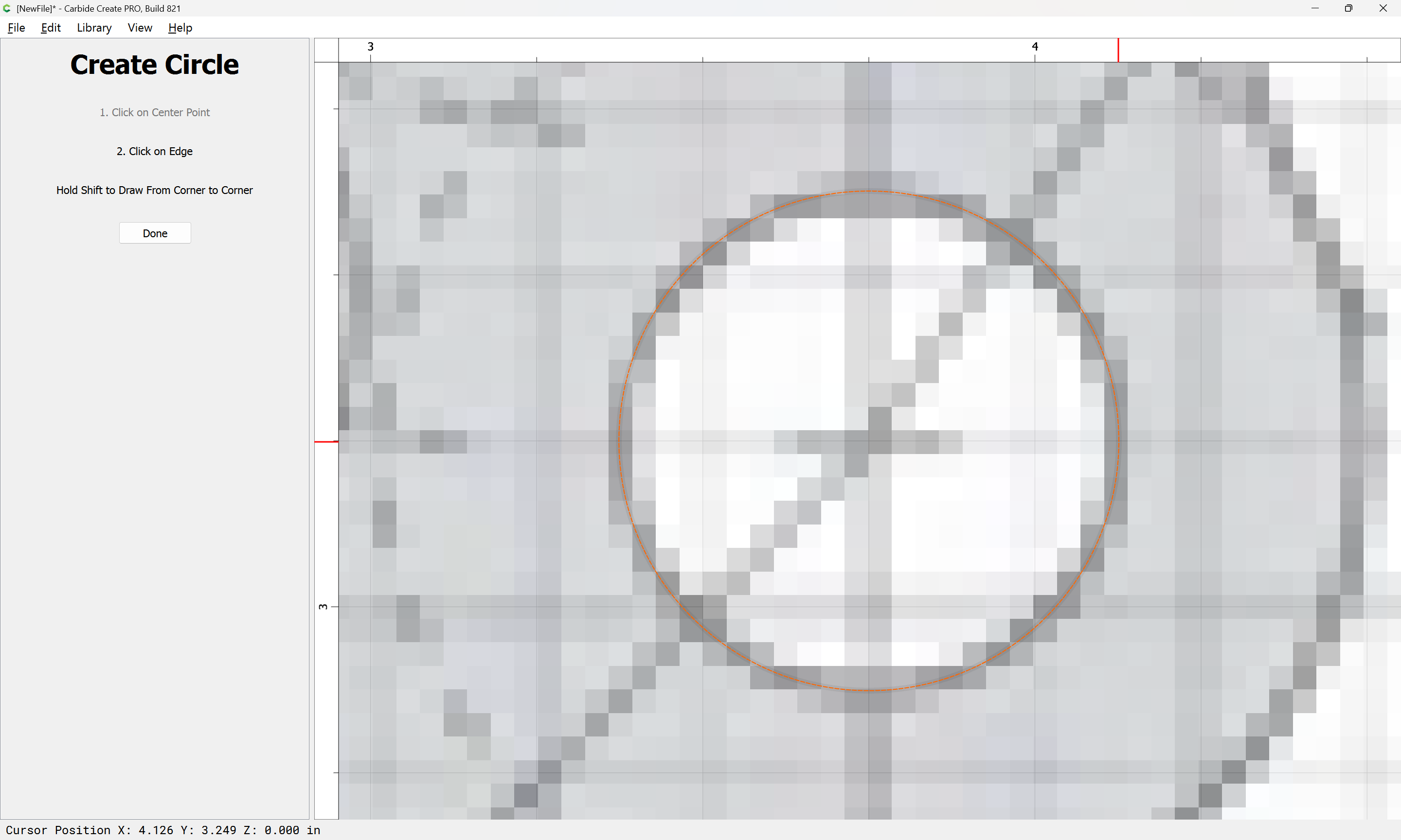
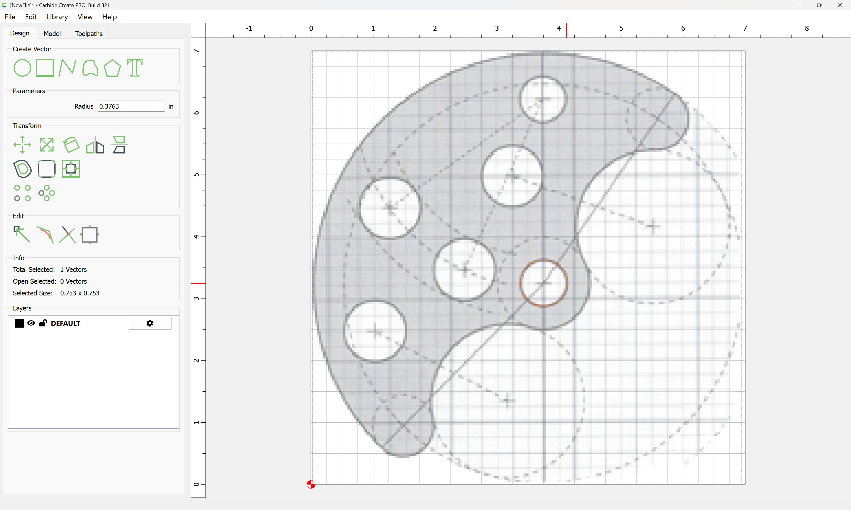
and copy-pasting and adjusting sizes:

and ensuring that things are aligned (since it’s not possible to drag by the center of a circle in the current beta):
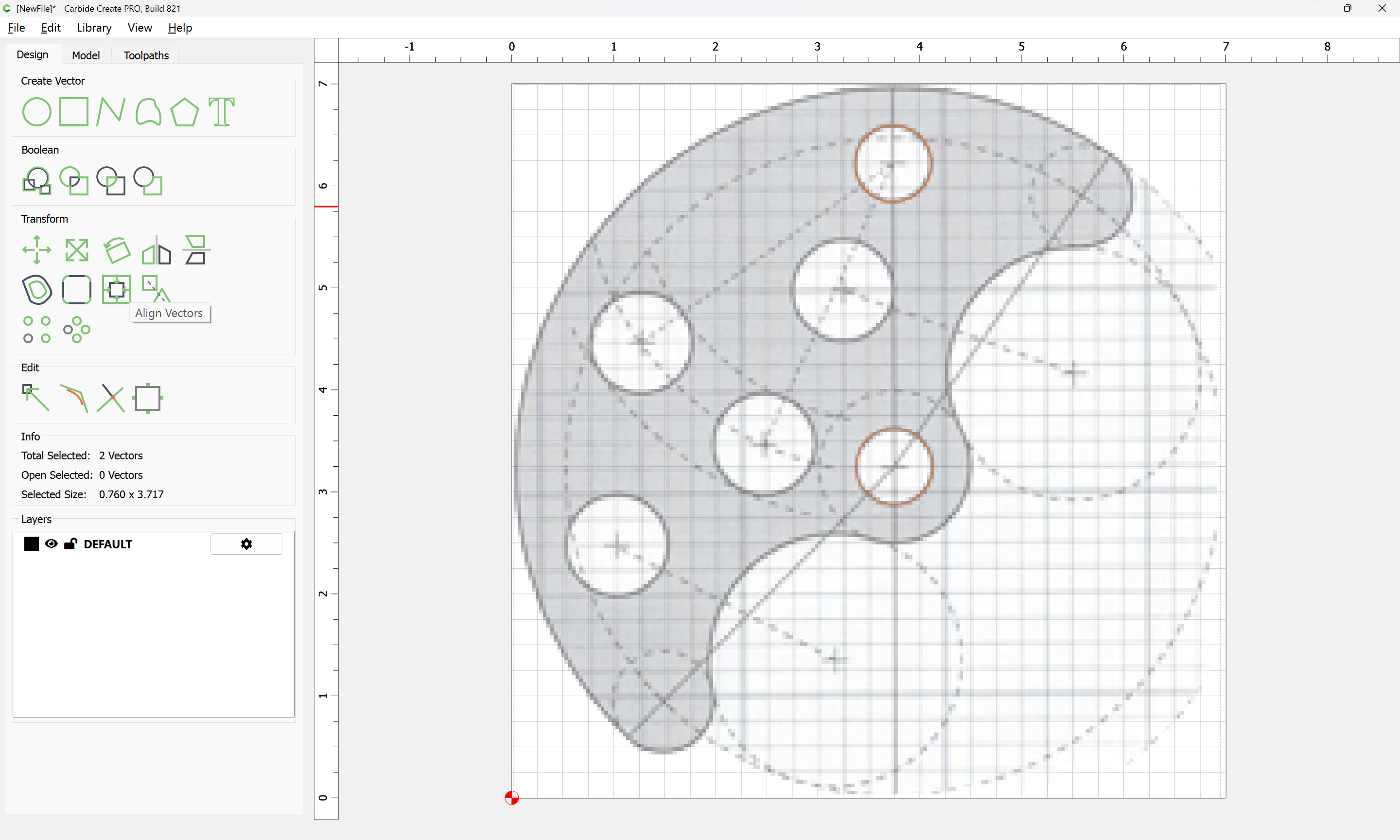
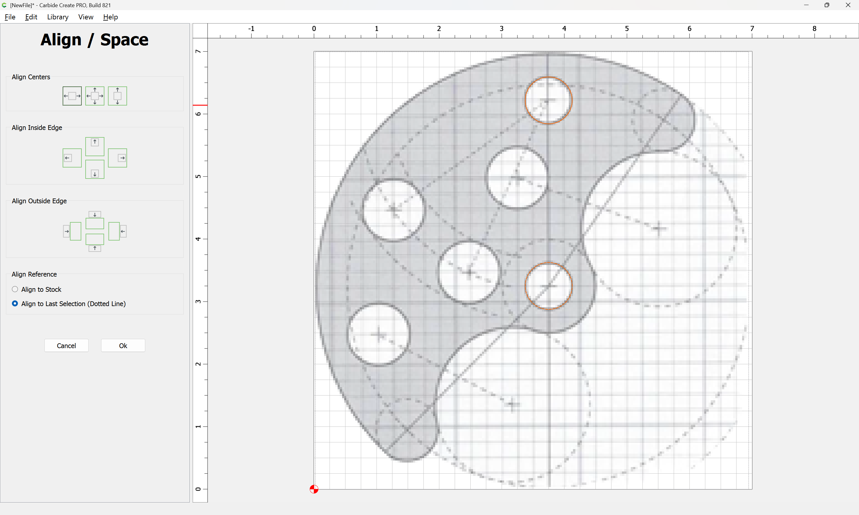
and drawing in circles for arcs:
and further drawing circles and forcing things to align where the coarse pixel grid does not allow them to:
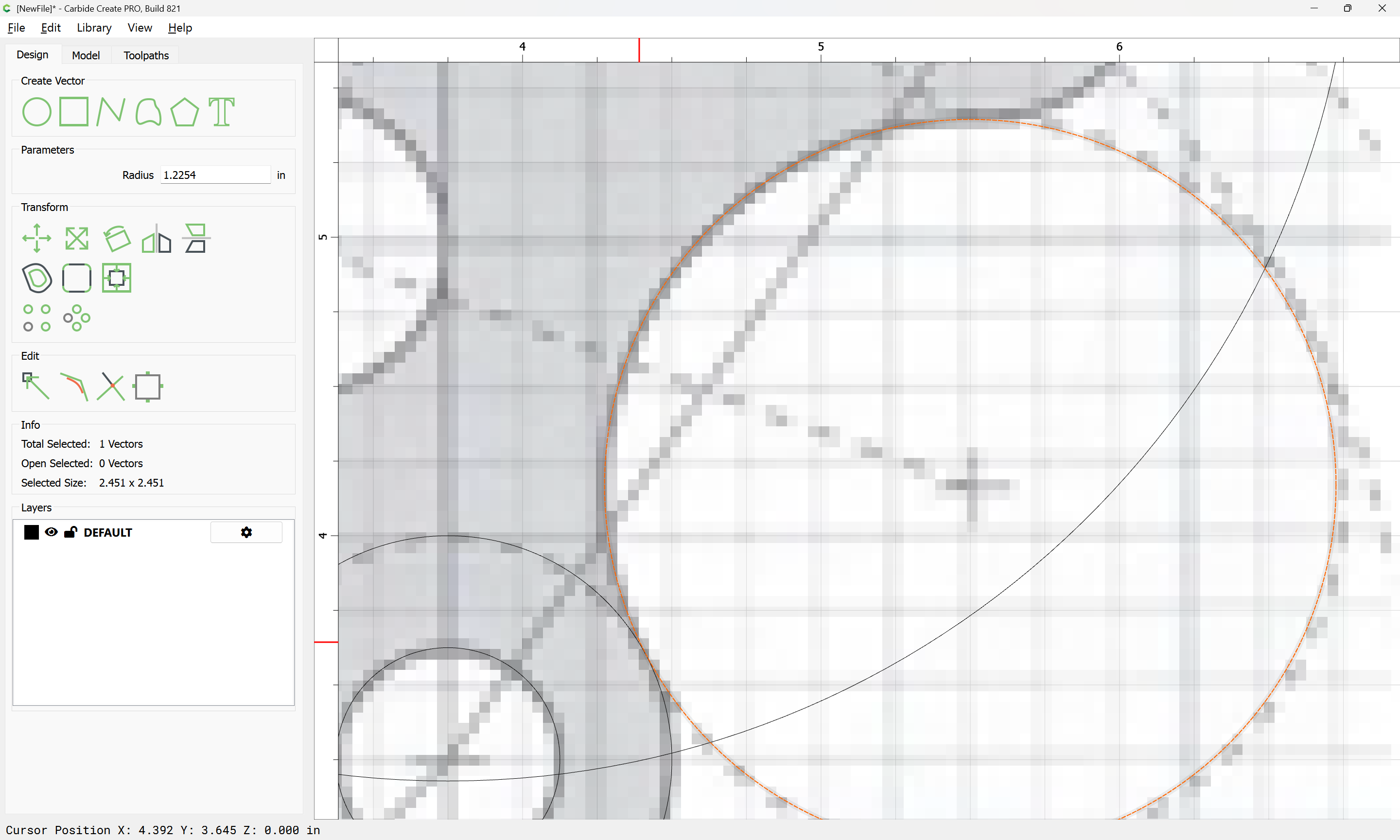
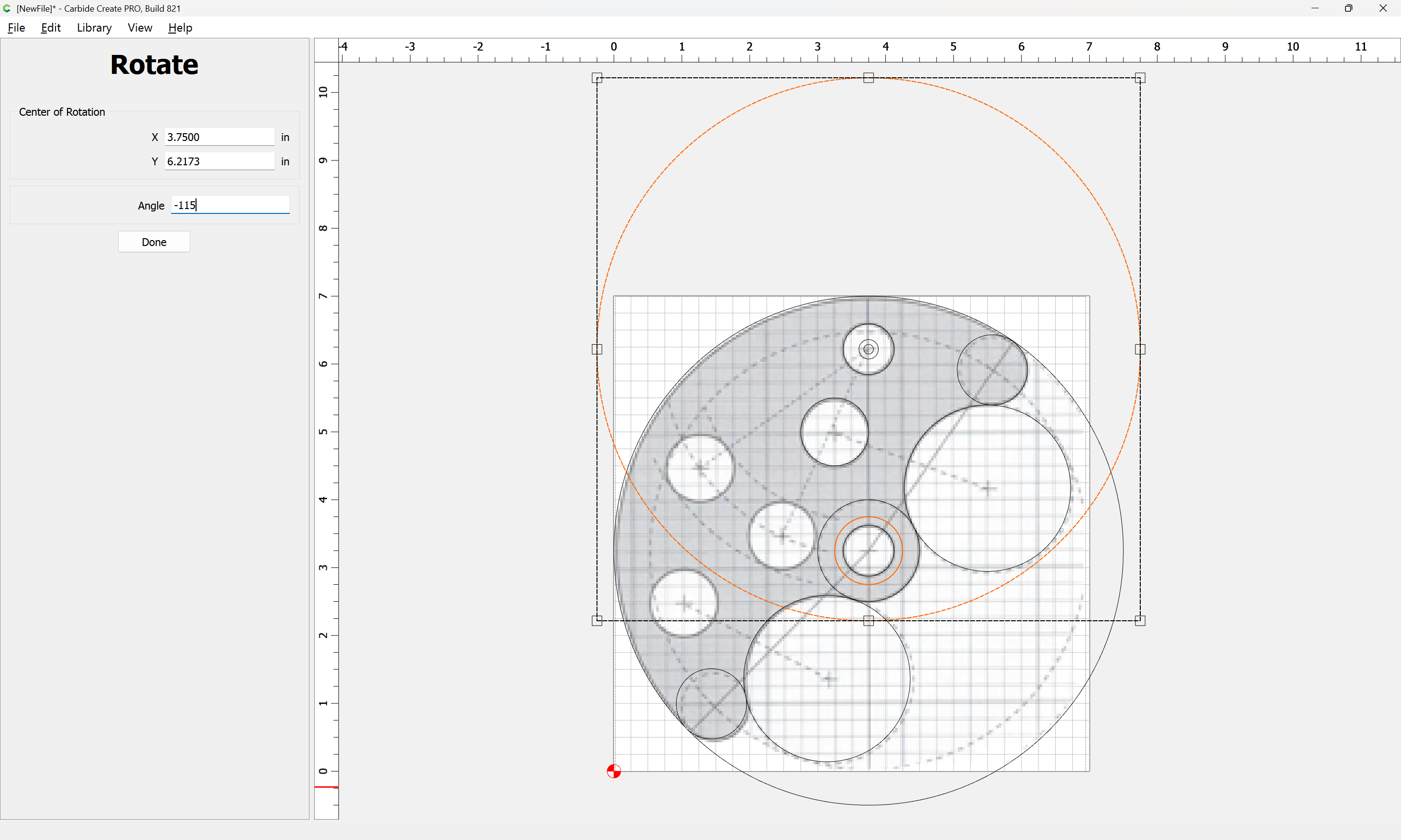
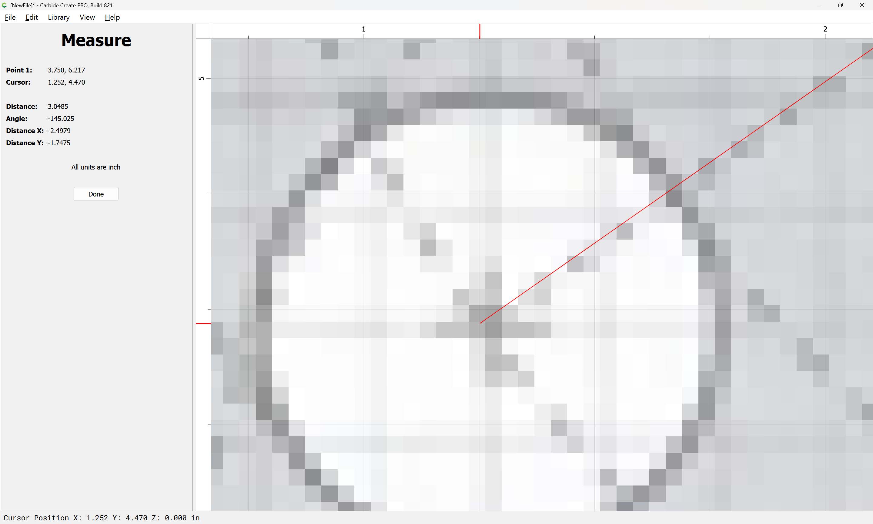
Note that you can use the Measure tool:
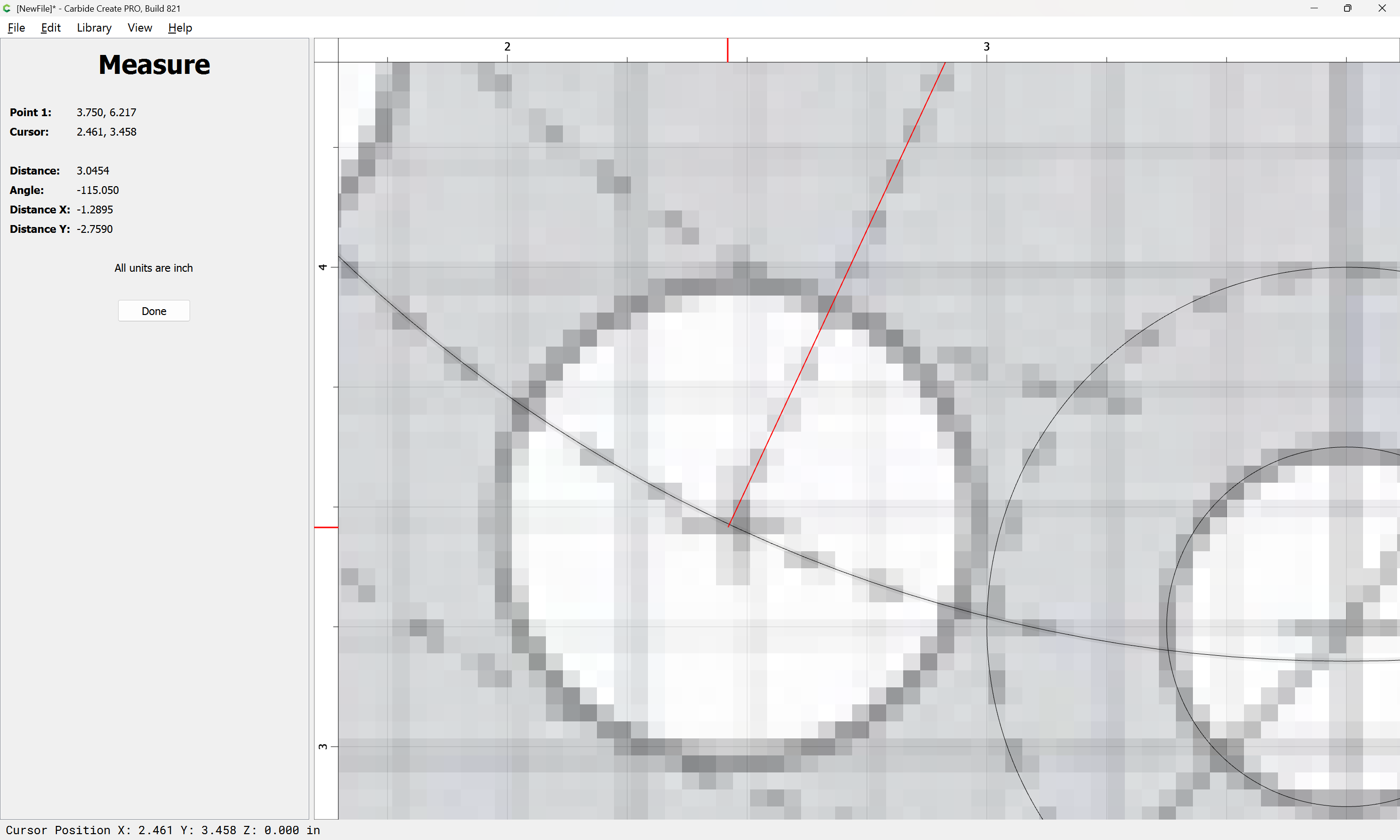
to get rotation and so forth — you’ll just want to increase the radius of the circle so that it is sufficiently larger:
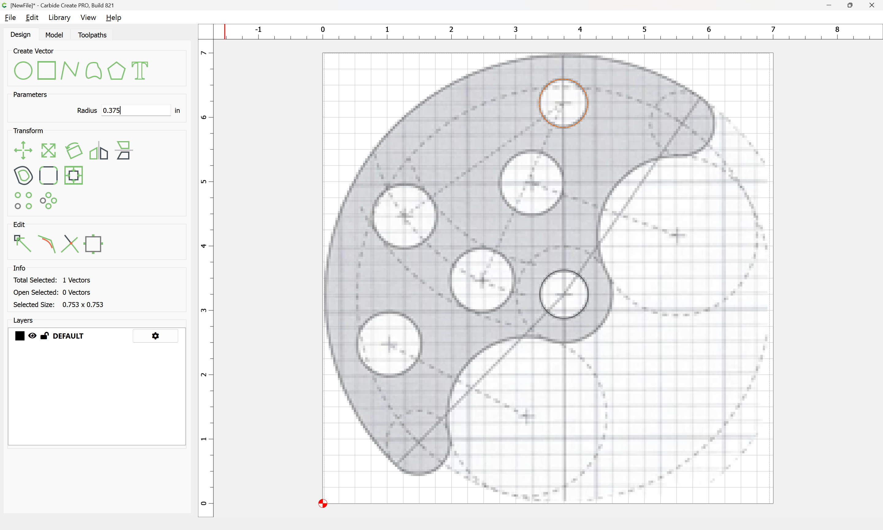
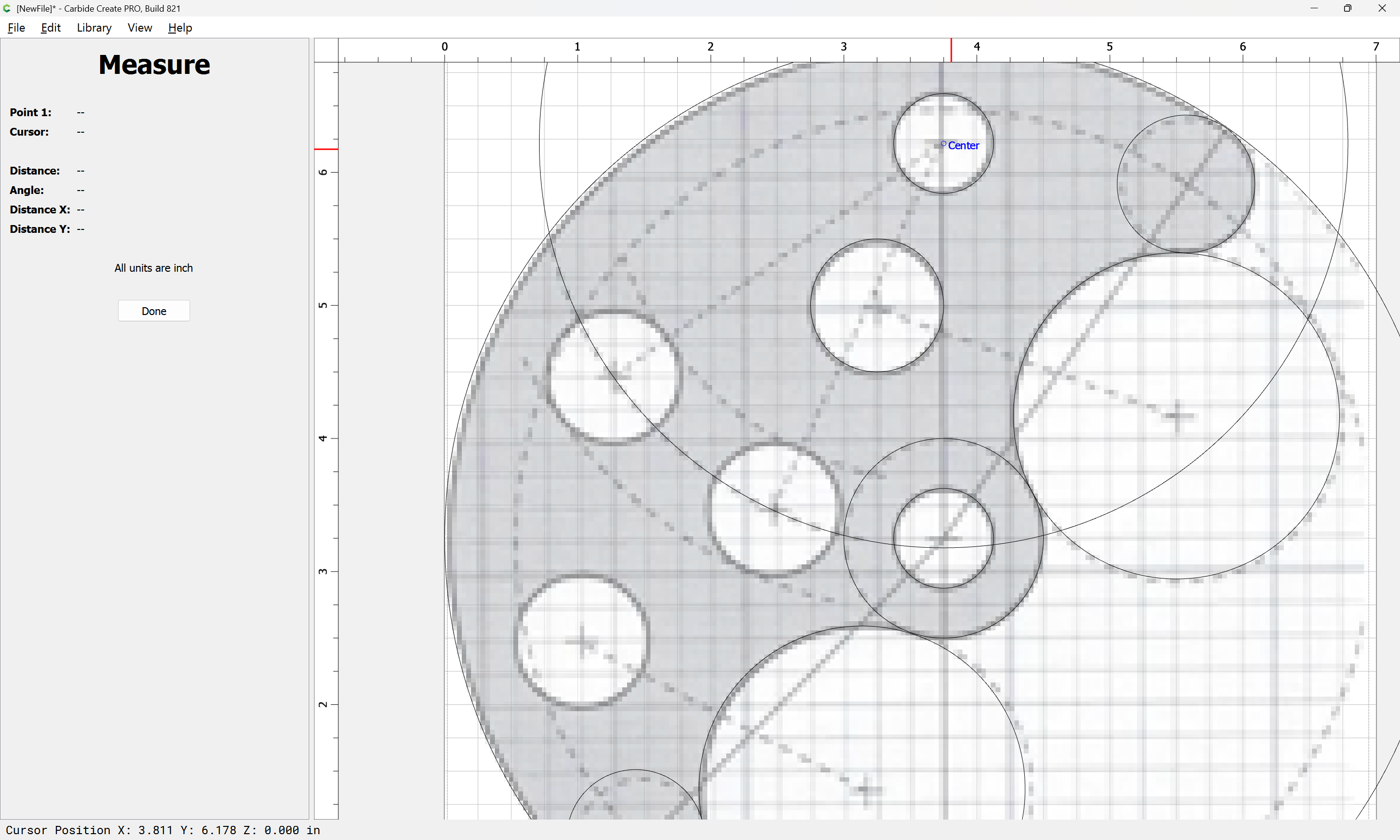
Then draw in a circle of the appropriate size:
and position it at the beginning:
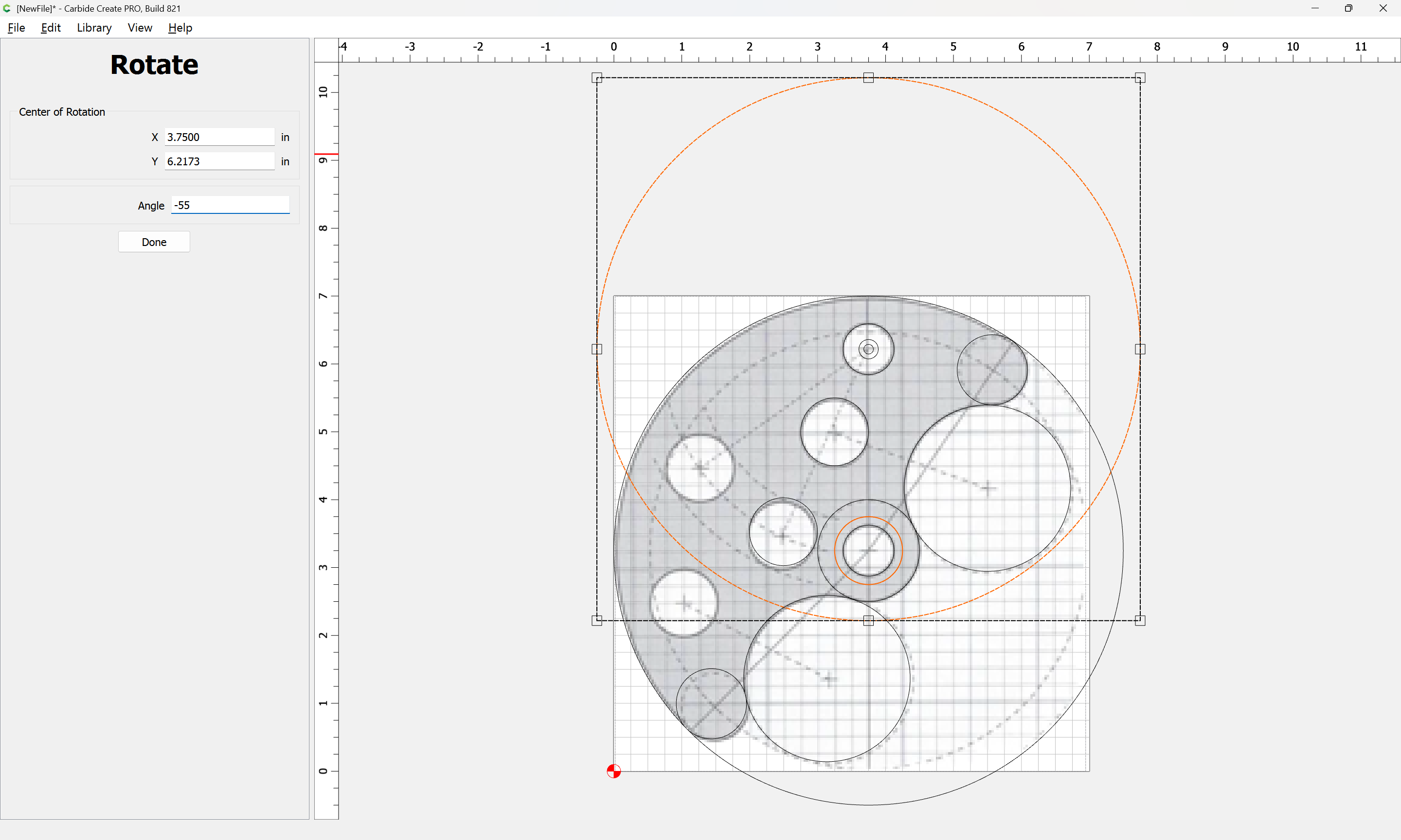
and then use the larger circle:
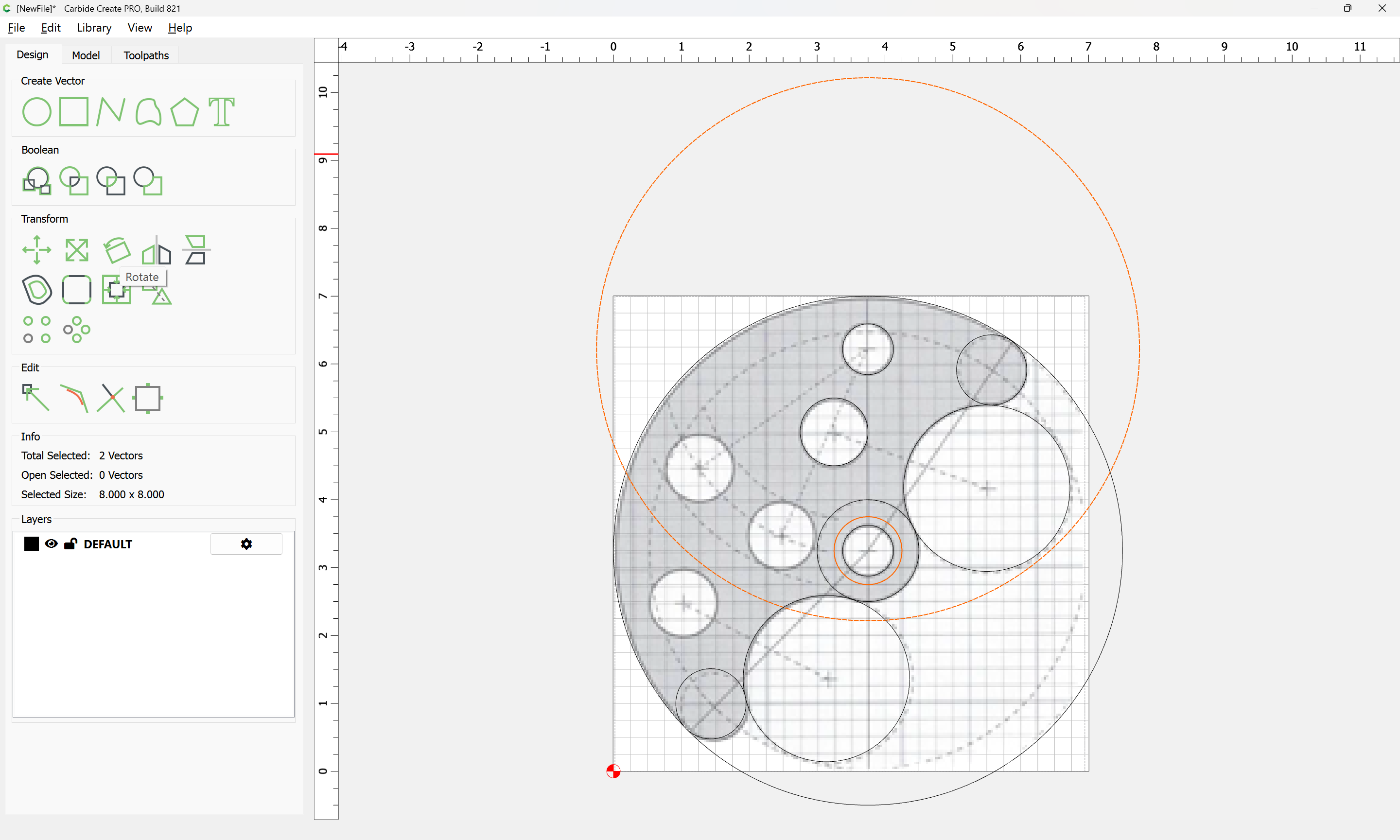
to rotate:

Repeating this for each other instance:
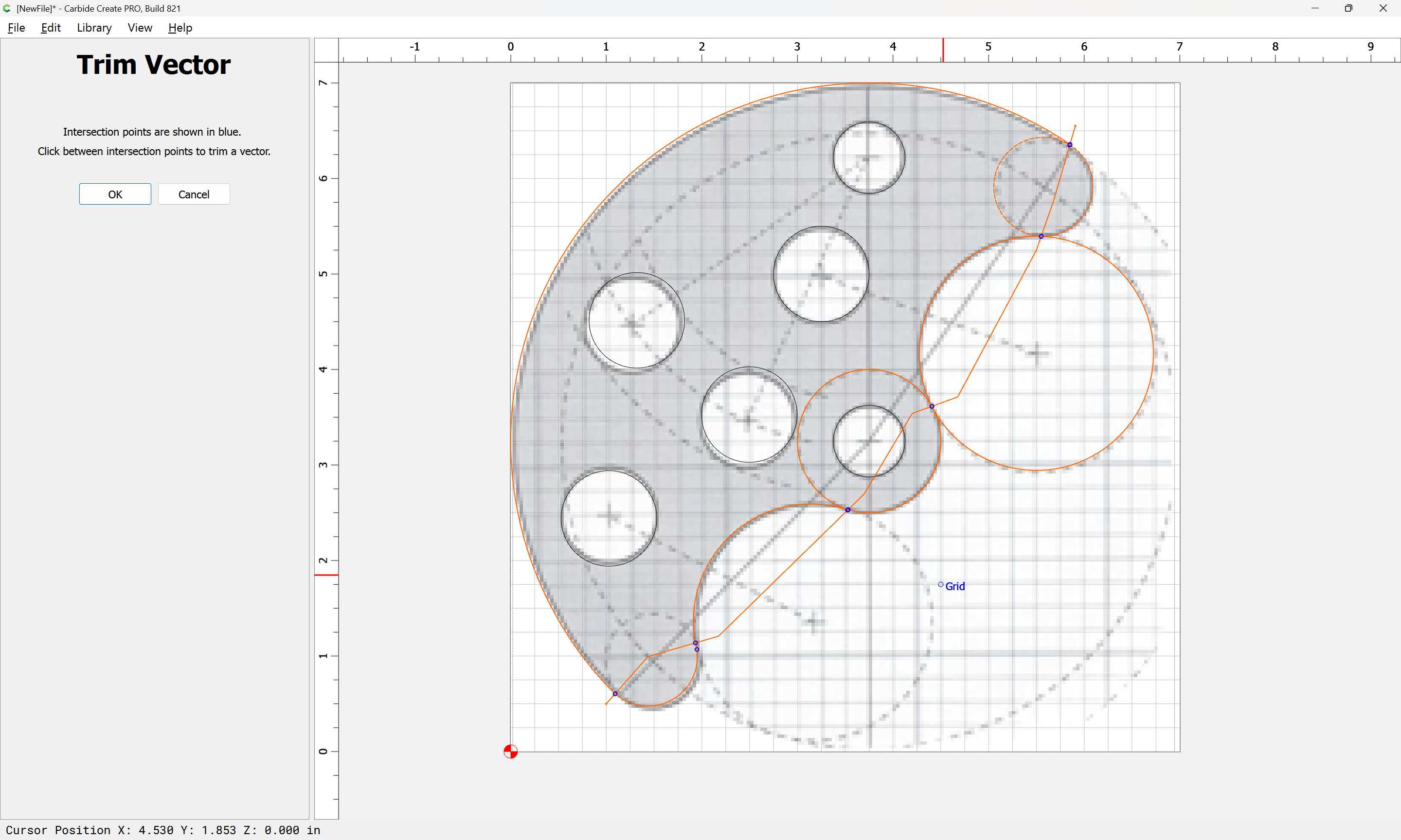
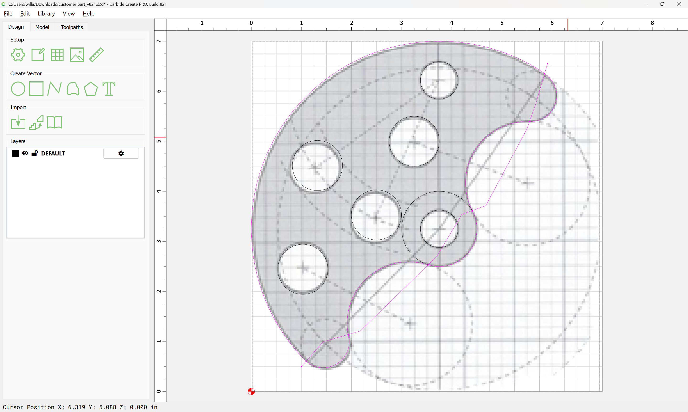
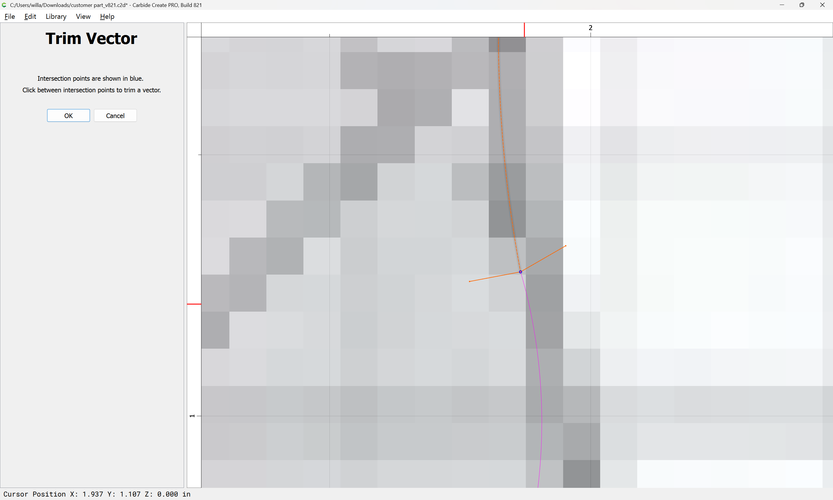
Once one has all the circular geometry drawn in, then draw in a polyline to define each point of intersection:
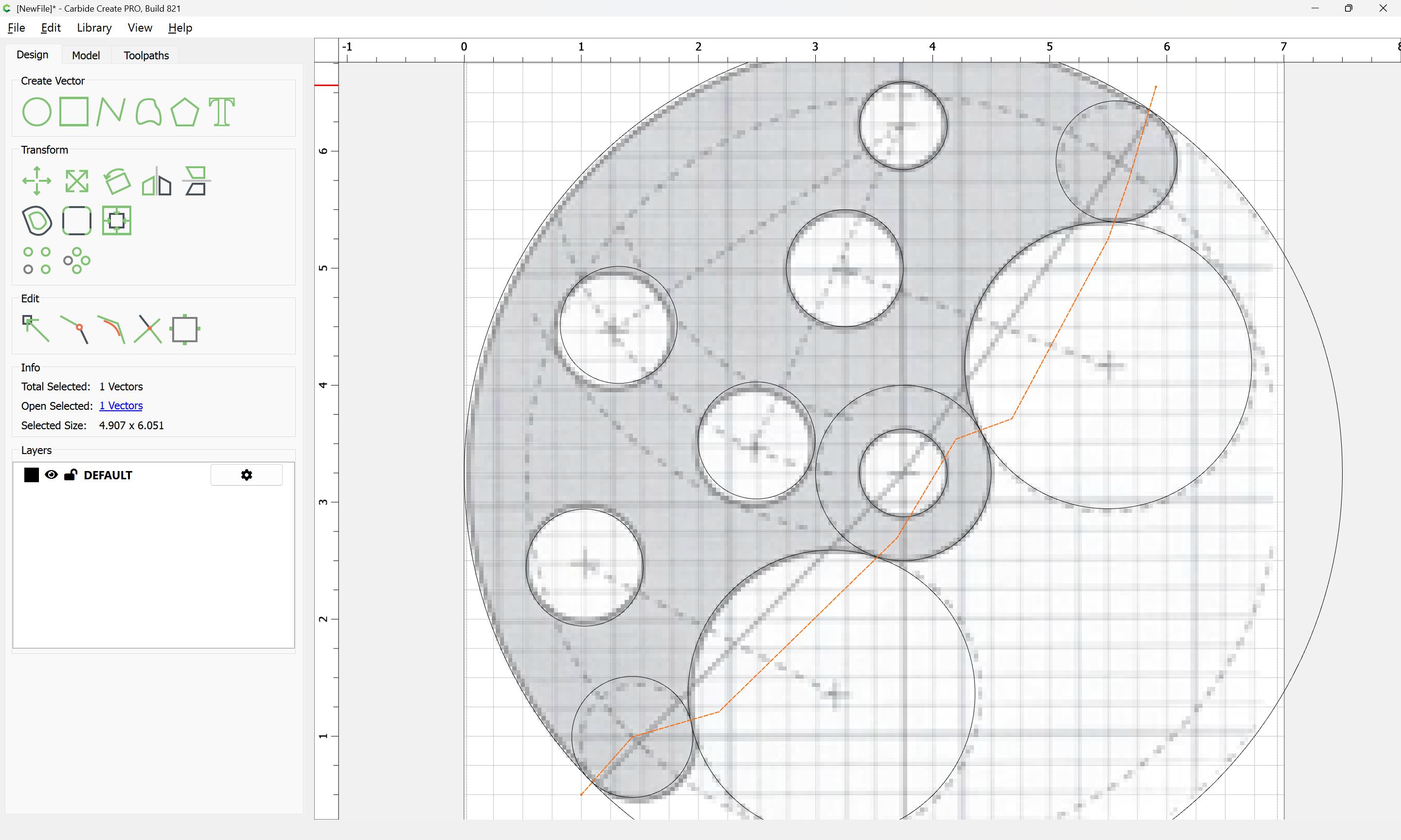
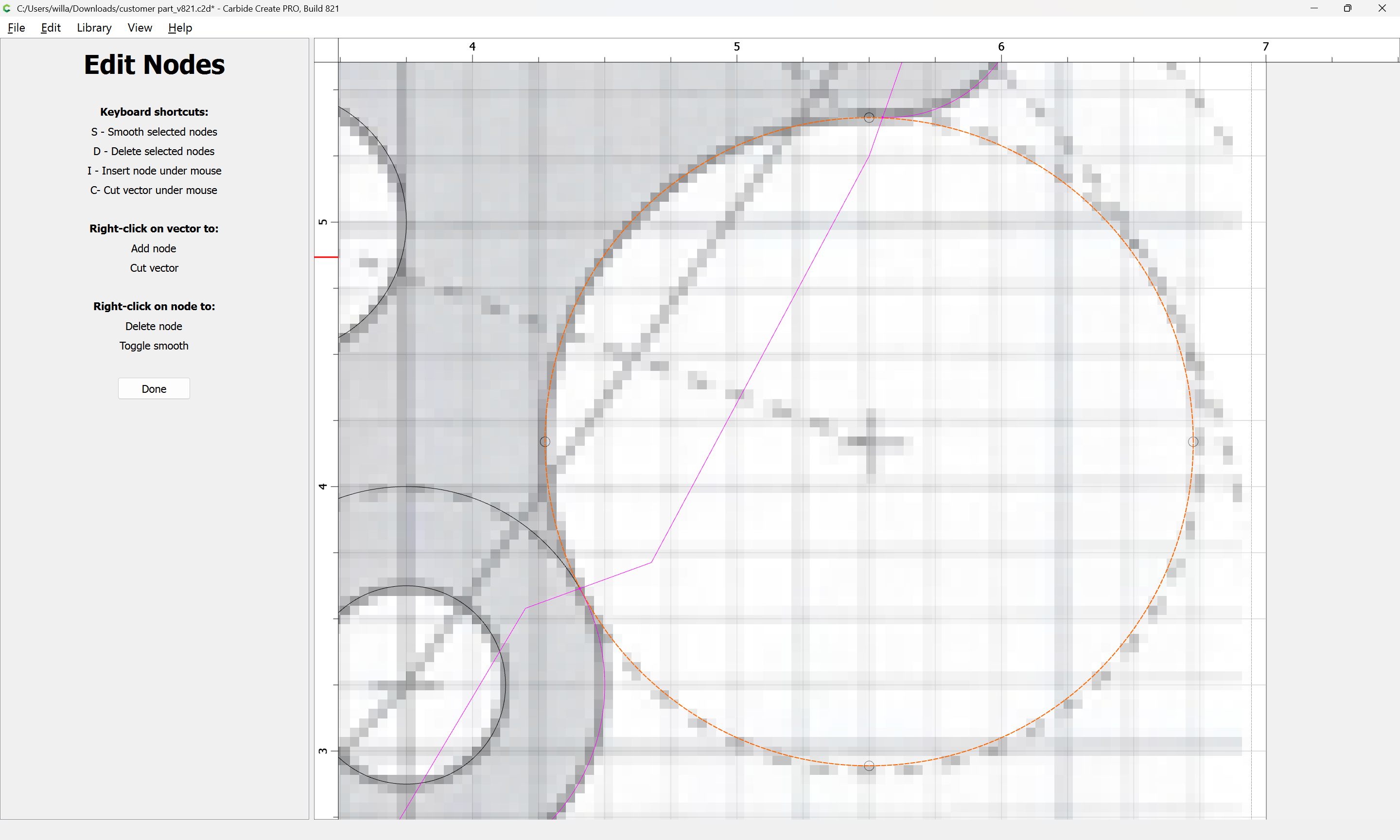
adjust as need be using Node Editing:
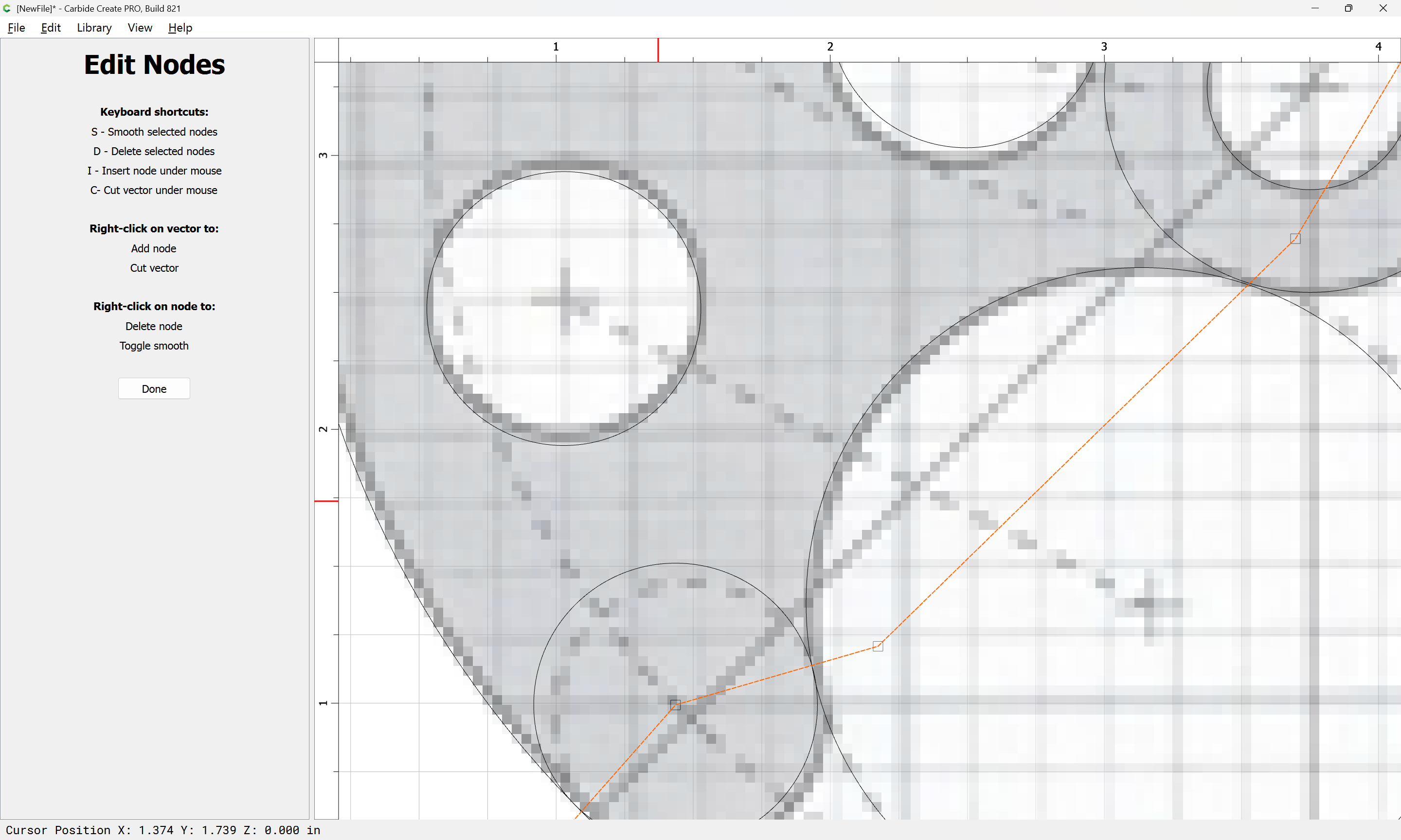
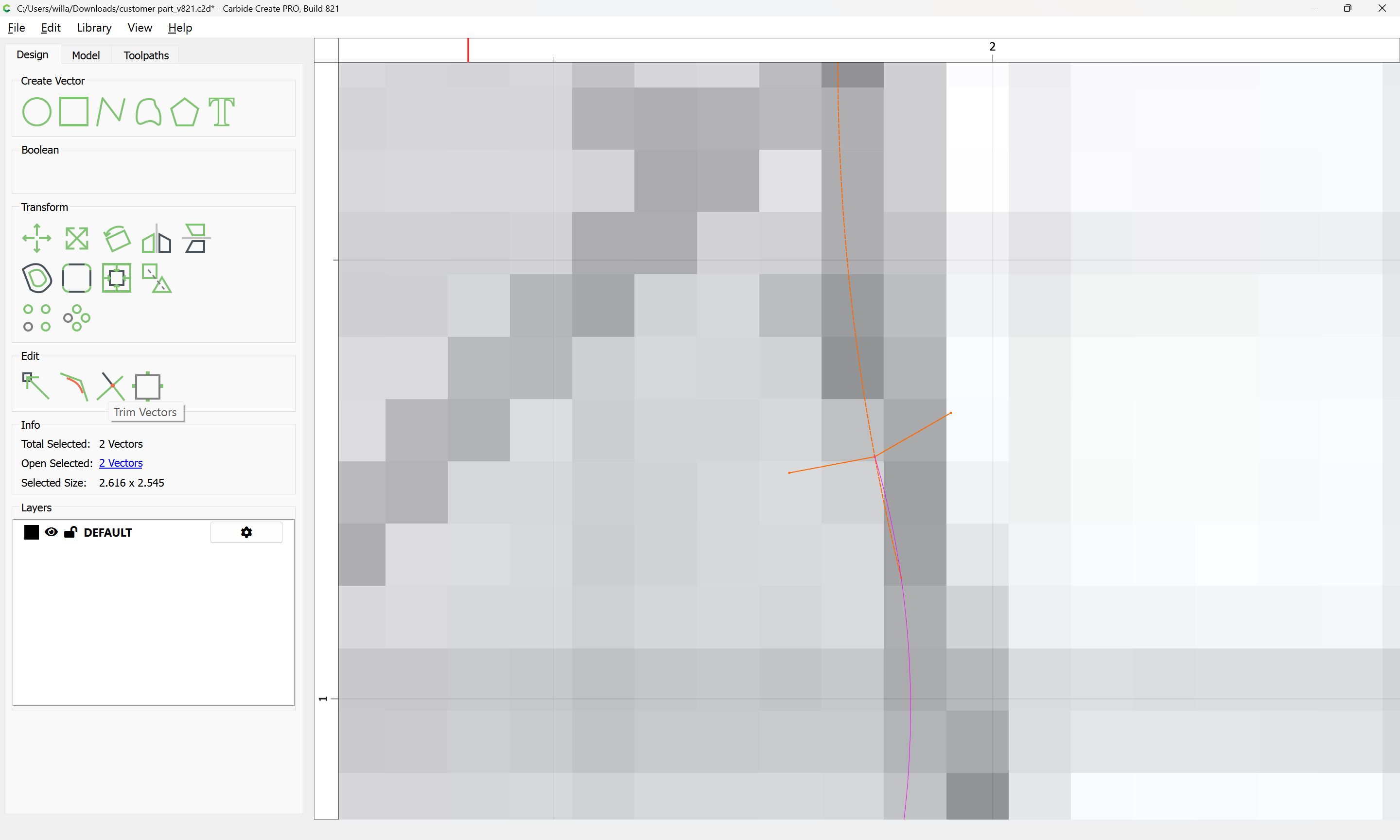
Then select the geometry in question:
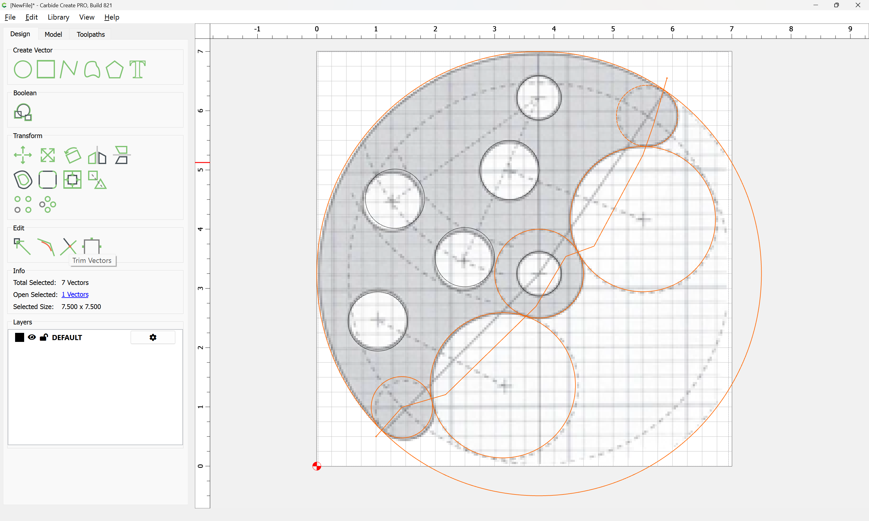
and use Trim Vectors to cut it down to only those parts which are wanted:
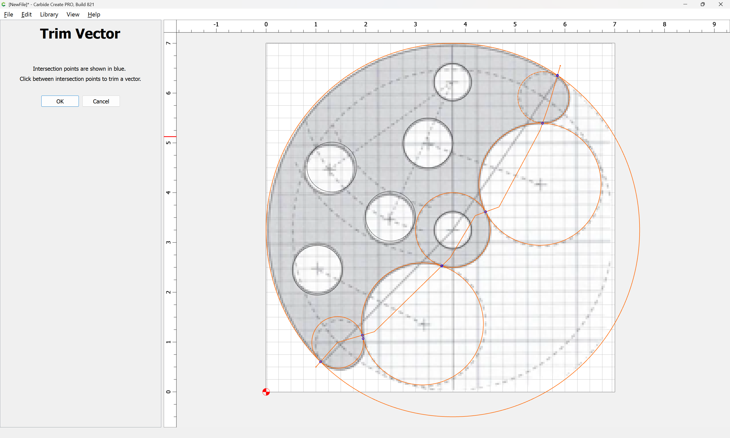

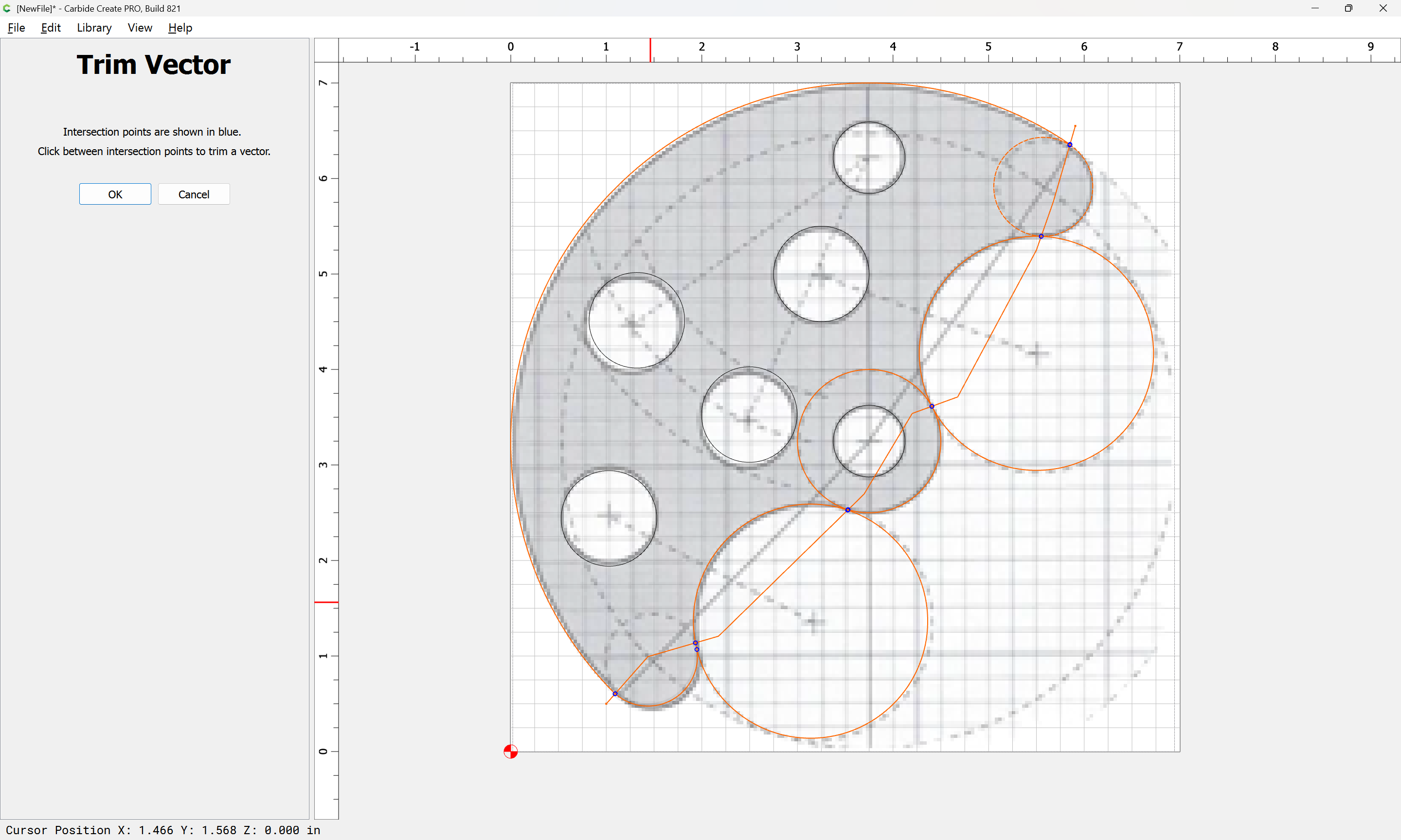
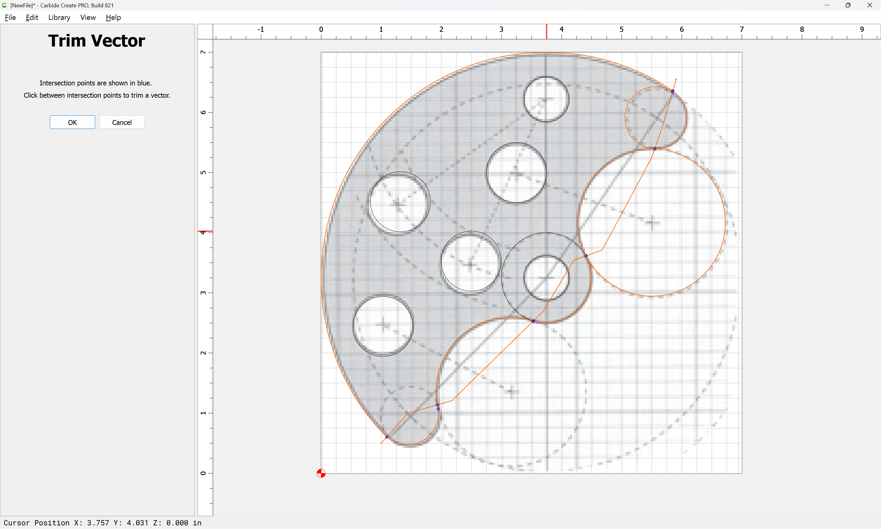

If need be click Done and reselect only what is not yet trimmed:
(or re-draw, or Node Edit)
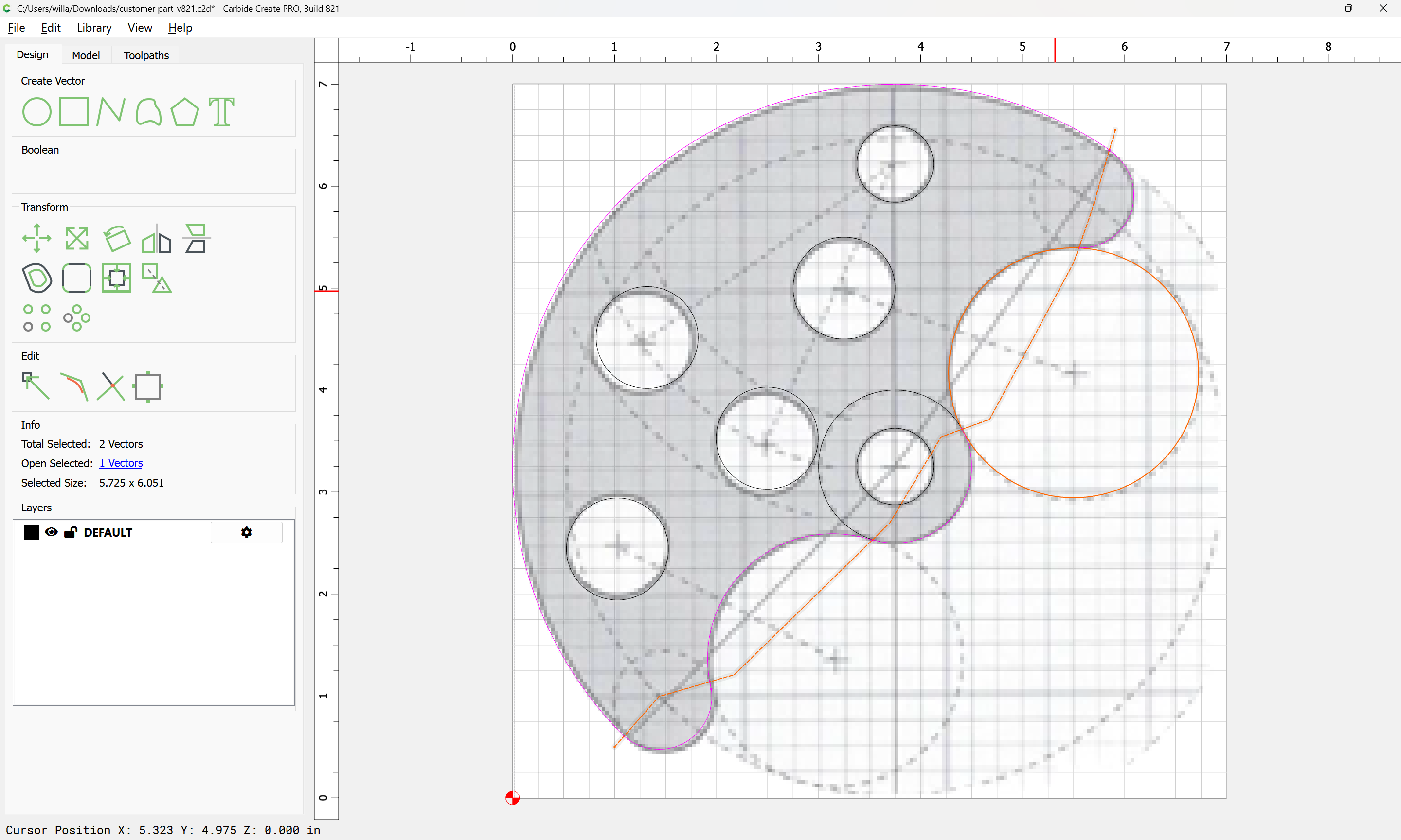
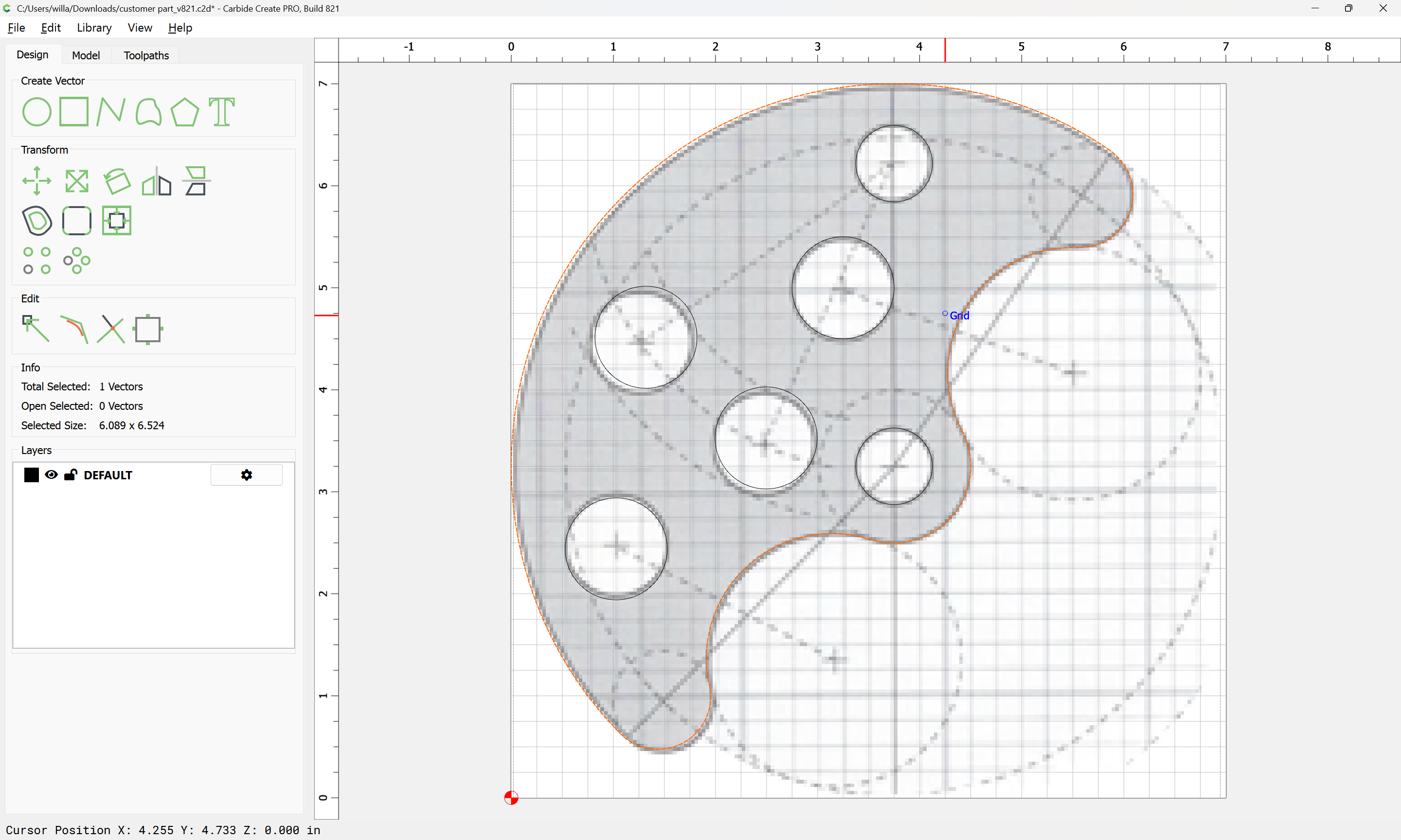
Eventually one arrives at:
and the polyline may be removed and the trimmed geometry selected:
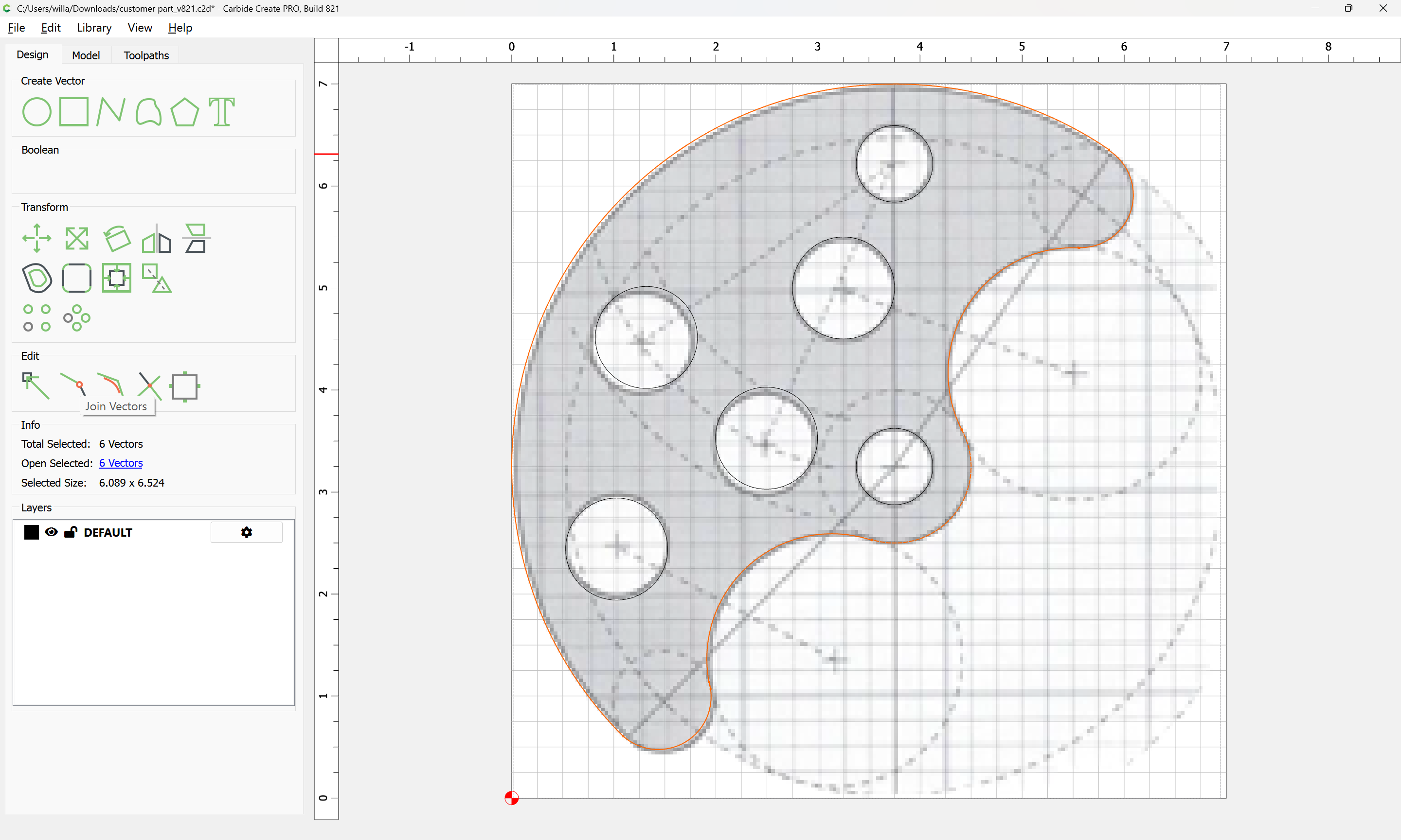
and Join Vectors used to close:
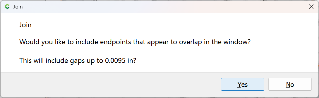
Yes
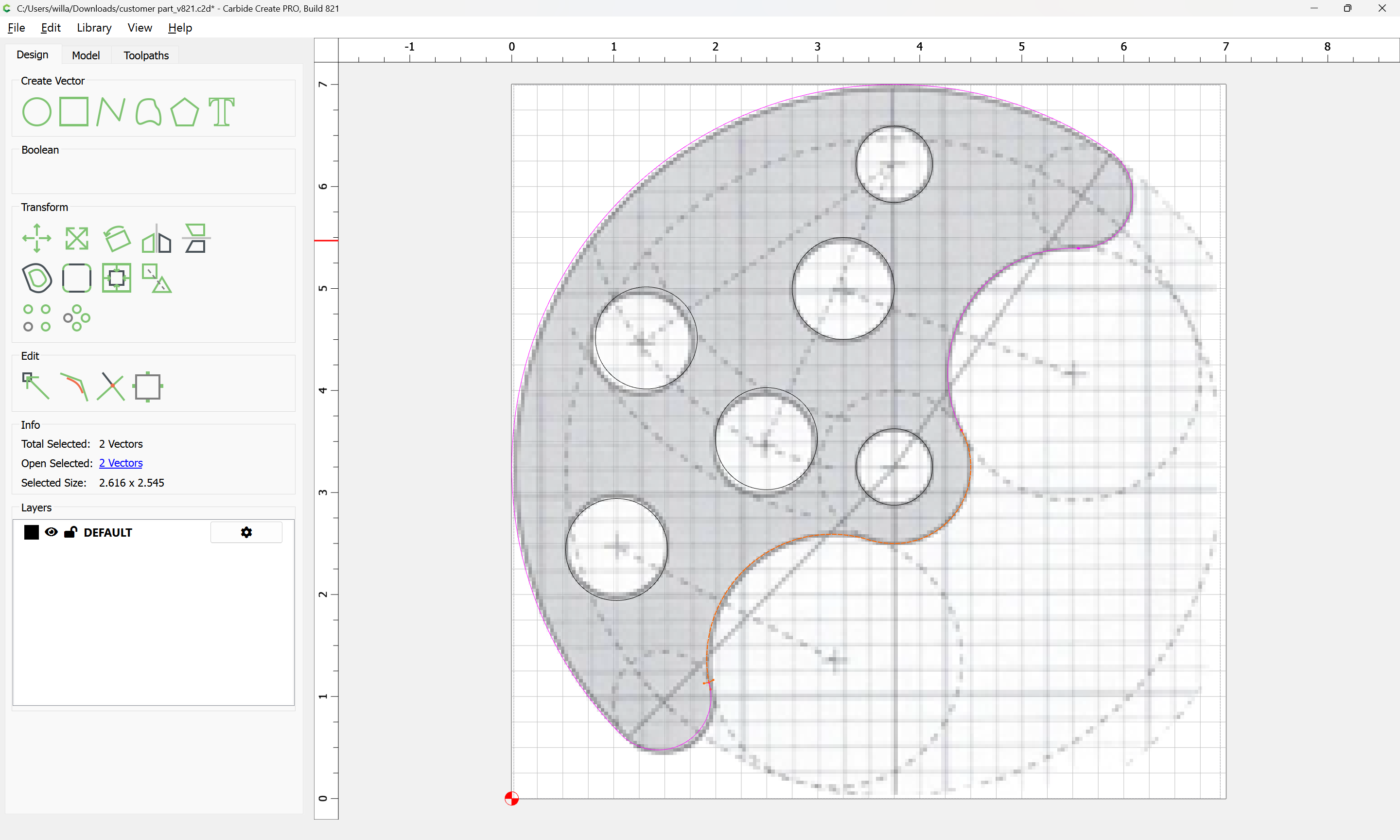
If need be, draw in geometry to trim again:
Eventually one arrives at:
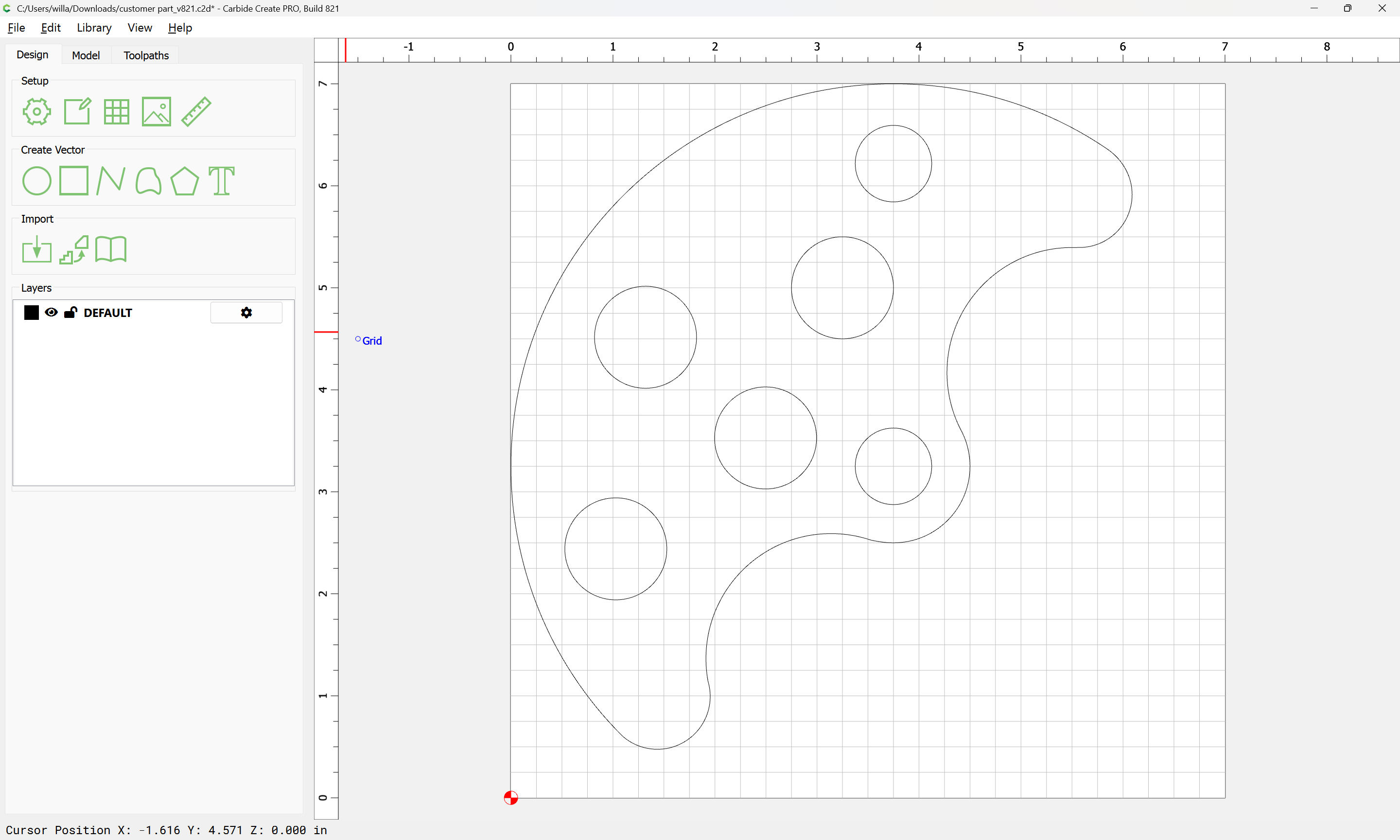
Attached as a v8 file.
customer part_v821.c2d (116 KB)
2 Likes