[Community campfire discussion] share your CAD/CAM/milling workflow and tips?

This recent post got me thinking that it could be interesting if we shared our CNC workflow/habits/tips here, since this a very general topic with lots of opportunities to mess up something at each step, and therefore lots of opportunities to have a few mitigations in place to catch the most common errors.

Mine is hobbyist/amateur-style, I don’t actually have a written checklist (maybe I should), but it goes something like this:

  • once a project idea has emerged, I rummage through my pile of material. More often than not, already at this stage I can be sidetracked because I stumble upon that specific piece of material I had set aside to use “someday”.
  • then I decide which CAD tool I will be using. Typically, that would be:
    • Carbide Create for 2D parts, 3D relief carving (ever since I had a taste of CC Pro + @fenrus STL2PNG online tool), and simple V carve jobs.
    • VCarve for complex V carve jobs and 2-sided jobs (just because the “top”/“bottom” view feature is quite helpful in that case)
    • Fusion360 for parts that involve 3D modelling, and for parts that I know will benefit from adaptive clearing toolpaths (e.g. cutting metal…).
  • If dimensional accuracy is going to be a concern, I anticipate that in the CAD either by using offset geometry (in CC or VCarve), or by using “stock to leave” in Fusion360.
  • I determine feeds and speeds based on my chipload religion, using a spreadsheet (my basic one or the great one from @gmack) or simply scribbling “FR = target chipload x nbflute x RPM” on a piece of paper, and when in doubt I’ll go and double-check what CC database says, what Winston says in his MaterialMonday videos, and if I am in a really specific case I’ll go search for posts on the forum (like, V-carving in metal ? let’s go check search for @Vince.Fab posts on that)
  • I’ll generate the G-code depending on which CAD software I used: the built-in proc in CC, or @neilferreri’s excellent posts for Vcarve and Fusion.
  • I’ll think for about 0.01 seconds about which workholding method to use, and choose tape&glue.
  • I’ll take a look at the surface of my wasteboard and go “yeah, that should do, I’ll resurface it some other time”.
  • I will try to install the stock parallel to the machine axes: usually using some marks in the wasteboard from a previous overcut, but I should probably get in the habit of using corner squares
  • when (or before) I load a G-code file, I like to double-check visually whether the cut looks as expected: I wish CM had a 3D preview pane, when I use CM I’ll go and check my G-code using an online G-code viewer (for some reason I keep going to this one), it takes all of 5 seconds and prevents the most likely error: stupid me selecting the wrong version of a file. I will usually look at the general shape of the toolpaths, the extent in Z direction/max depth of cut, AND where I set the Zero.
  • for zeroing, to this day I still use two methods:
    • good ol’ paper touch off, when only accurate Z really matters, and I can eyeball X/Y. It’s accurate enough for many of my usecases. I hear people using feeler gauges, maybe I’ll try that instead of paper, someday.
    • probing: whenever I need accurate XYZ zeroing (typically: metal job referenced to top left corner). I also like to use a probe when using V-bits, because it’s easy to be inaccurate with those bits using the paper method.
  • for tool changes, I like my BitSetter a lot, so I’ll use that whenever I can, either from CM, or from CNCjs. I try and switch off the router power while changing the tool (since I don’t want to trust that single PWM wire to not turn the spindle back on at the worst moment, should a bug or hardware failure occur).
  • since I have a spindle, I don’t have to worry about turning the router on and off, the G-code takes care of that for me. If only that feature were available to router owners…
  • After I have zeroed / bitset, I’ll close the front door of my enclosure, then turn on the vacshop (OR compressed air jet for metal work) from my poorly made control panel.
  • And then hit “run”, with my hand near the E-stop button.
  • I’ll stay at the machine side, maybe doing something else on the computer if it’s going to be a long job, but always, always within hearing distance. And I have a fire extinguisher in the garage, should things go south in a very very bad way.
  • then switch off power on everything, and grab that scraper to gently pry the piece off the wasteboard. OR, leave it there if I want to test-fit another part in it, or if I want to measure some dimension on the part. I will often leave the part on the wasteboard, regenerate a toolpath with lower stock to leave (possibly negative values, if a pocket needs to be a bit larger than I had anticipated for a perfect fit), and run that additional toolpath. If I had a dollar for everytime I prematurely removed the part from the wasteboard, only to realize 2 minutes later that I needed to run an additional finishing/adjusting toolpath…
  • Regarding leaving the machine turned on between jobs: I will usually leave it on if I know I’m going to run the next thing within minutes OR if I can’t risk any subtle shift in the zero (but honestly, in 99% of cases for me, re-homing is no issue. It might even be beneficial since there is always the remote possibility of a lost step in the previous job, and re-homing would fix that). I have inadvertently left the machine turned on for hours before, and apart from moderately hot steppers, nothing happened (yet I prefer to turn it off when I can, it makes me sad to think of those stepper motors struggling at their max power to just keep the machine in the same position. They’re like sharks, some can stay motionless, but moving is what they do best).

I’m pretty sure I forgot things I do without even thinking (yet another reason why I should probably write a checklist someday), but this post is long enough as it is…

So what about you guys ?
8 Likes

Hmmm… Lets see - I don’t think I would count them as “tips” but here are a couple things I do perhaps a little differently.

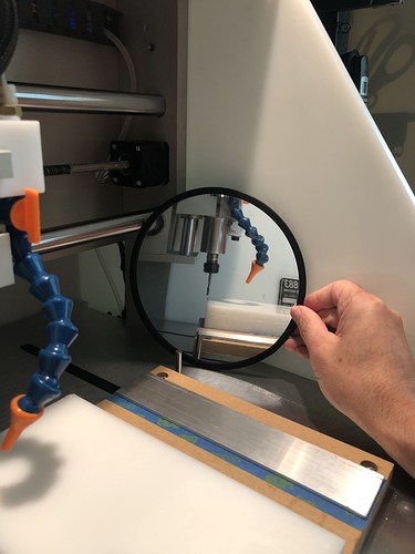
#1 for setting Y zero on an edge where I am not super fussy about getting it right on but need to be “in the ballpark” I use a mirror to line up the edge of the stock and the middle of the end mill as trying to stick your head in the Nomad is just ridiculous and paper on the Y edge requires more fussing and a bit of math. Very tempted to drill a hole in the side of the Nomad so I could just look through instead but it hasn’t reached that “damn the torpedoes where is my drill” moment.

#2 This is a new one and it evolved out of not getting great consistency with using the “slip of paper” method for setting Z height. I get the Z height close and then turn on the spindle (for the Nomad using the “Spindle On” button in the UI). Next I edge the spindle lower using the smallest jog increment until I just hear it rubbing the stock. Up one click on the Z height. Done.

4 Likes

Cool tip! that mirror should come standard with the Nomad3 :slight_smile:

1 Like

I wonder if one couldn’t use a set of them similar to the mirrors pilots use when landing on carriers.

3 Likes

The simple solution here is for C3D to add a round hole with a removable plug on one side of the HDPE siding to look through when required OR use as a hole for a dust boot vacuum hose.

2 Likes

I’m doing more measurements to see if I can get a consistent X, Y backlash estimate to put into the models pre-cutting, it would be very nice if GRBL had the backlash compensation logic that Mach3 and others have.

I definitely get the digital calipers out if I am going to need fitting parts from multiple operations.

I still use clamps to the T-Track or M6 threaded inserts quite a bit, but they’re a lot of work, must use tape & glue more until I understand where it works well.

Mine normally looks like the Mars Rover should be driving on it, but all the highspots are in a single plane :wink:

I have found a grid of 10.2mm holes and a bunch of short 10mm soft Aluminium rod locator pins are excellent for this, locate the parts square and consistently if you have several parts needing the same toolpath and X, Y zero.

I have found that a V bit and a phone camera zoomed into about 4x is a great way to hit a marked point on the stock if I have no handy corner for the bitzero or edges for an edge-finder. This is my tactic when the piece is way to big to fit on the bed or for the machine to reach the edges.

Why not grab a latching switch and stick the NO side of it in line with the PWM signal with a 100k resistor to 0V so you have to press in the “engage spinning death” button to let PWM control the spindle?
(there’s probably some signalling on the HY VFD connector we could use too)

And sets the spindle to the correct speed so you don’t sit there thinking "It’s making hard work of this contour cut, those chips are the size of pencils, oh, the VFD is still on 4,000RPM warm-up not 20,000RPM, oops :frowning: good job the spindle has all that excess torque eh?

I wondered about whether the effort of wiring in the E-Stop was worthwhile, I no longer wonder.

I tend to turn the machine on and warm up the spindle when I start for the day and turn it off when I’m finished, or messed up badly enough to E-Stop.

My opinion (having done a reasonable amount of reliability analysis);

Electrical power systems and electronics generally fail when they are being turned on and off. Sometimes this is a revealed pre-exising failure, but frequently it’s due to power and thermal cycling stresses. There are few elements of an electrical or electronic system whose lifetime is dominated by a wearout failure characteristic (excluding rotating disk and SSD storage).

The Shapeoko does have a bunch of wearout failure components such as the steppers, when they are moving, the bearings, belts, home switches, drag chains, flexing cabling. These are all likely to fail with cumulative movements with some factor for how “hard” they were working whilst moving.

The steppers run so cool on these machines that there’s unlikely to be any statistically significant impact to the service life from leaving them powered up. Whilst the stepper driver ICs will have a reduced lifetime related to operating voltage and operating temperature the drivers seem to run pretty cool with that big Aluminium heatsink they’re attached to, and the Y rail extrusion.

So, I err on the side of turning the Shapeoko PSU and control electronics on and off less often if possible, but that’s just my opinion, others will likely disagree.

3 Likes

I didn’t think about this until it came back up, so, knowing that there will not be a lot of agreement with my here, and following @Julien for structure:

I’m kind of in between hobby and professional here. CNC is not the major part of my work like with a few people here, but it is a core part, both with my teaching hat on and my engineer hat on, and I use the machine for hobby things as well. It is a tool to me. A really nice tool, but a tool all the same. After all, when was the last time you had the thought: “I have a really awesome pin nailer. What can I pin nail today?” When it is the right tool, or the best you have available, you use it.

Material: Some projects are designed based on what is on hand, but rarely does available material dictate more than setup stock size. If I don’t have a material that is appropriate for the task, I get it.

My CAD: 80% Inventor, since I teach it and use it professionally. The other 20% is mostly SolidWorks, with a little traditional AutoCAD and some Fusion sprinkled in for flavour, as well as the occasional foray into other tools for special purposes. For electronics, I still have my license for Eagle, from back in the day. I have tried stepping away a couple times, but entrenchment is a hell of a drug, and I have maybe 25 years worth of component models, designs, and experience.

In most cases in which dimensional accuracy is key, I test the tool on the material to be used and make sure that it is properly sized in the tool library, then structure so that I can break out the dimension critical operations for tuning. A test cut of the geometry, or oversizing with stock-to-leave, or surface-offset in the model, or a combination are used. When I can, I leave final ops for these features until the end of the job, or at least a setup. This both helps insure the result is accessible to measure, and reduces risk of changes due to heating or relief of stress in the material as other cuts are made. Always consider HOW the feature will be measured without removing the part from the machine. What tool, will it reach, is it precise enough, how precise is actually needed, and so on.

My feed-and-speed religion: On the Nomad, 10KRPM and feed for appropriate chip size for the material. For the small tools suitable for the machine, lower RPM doesn’t pay.

Gcode: Inventor CAM (formerly HSM)/FusionCAM does a generally good job with lots of strategies, but there are cases where I just code it by hand. Some simple features do not CAM easily (like the fillets on the gas connector caps in my post the other day). The general rule is axial engagement 1 to 3 tool diameters, radial 25 to 40%, unless there is a reason to reduce.

Workholding: Here I use a variety of methods. I prefer tape (not tape and glue, just a precision carrierless adhesive, with 467MP being what I keep on hand most of the time). I use either a wasteboard or aluminum bed-of-holes plate, and aside from adhesion, I will clamp with edge clamps and/or hold-downs, direct screw down, alignment pin, and friction fit into a pocket, or a combo of these. I think that for contest10 I used all except the clamp. The wasteboard is a consumable. I consume them. I surface or pocket to mount parts and get clean alignment as needed. It is usually faster (and cheaper) than having a part ruined or a tool broken, or both. For a lot of things rectangular (circuit boards, for example) I go with surface and two registration edges such that the zero is in a corner. I have a few wasteboards setup for particular things that I will swap in and line up carefully when needed.

Simulation: “If you don’t simulate, you will mutilate.” Key. Then double check. Everything. The depths. The zero. Everything. One of the reasons I like to pocket the wasteboard or use dowel pins to fixture. One zero to rule them all for all setups for a project. Sometimes, a second zero, but offset by a simple measure, like 3mm, to make resetting easy.

To set the zero, several approaches I use when needed. I have a sharp-point tool and can hit x and y within maybe 0.05mm if there is a clean edge to find (magnification is your friend), and for z will use a plastic or brass shim (0.500mm plastic is what I currently have on hand)- slowly lower until the shim will not slide under the point, then raise by minimum increment until it does, and figure that is within 0.01mm). I have also been known to clip the leads from a continuity tester to the tool and the part when working with metal, get close by eye and feel, then step minimum steps to contact. I use a gauge pin for this method. I like gauge pins. There are several size I buy in multiples to be used for calibration. If I can avoid the need to precisely zero, I do.

Tool probing is built into the Nomad so not relevant. Ditto for spindle. Major considerations when I bought the machine.

Chip evacuation and airflow depend on the job. The Nomad is enclosed enough that for many things, I don’t need to use any. I have a small blower line that I use, and a hole (with plug) in the side for a shopvac hose when needed.

Part removal depends on mount method. Anything from loosen a clamp to pop it off, to planning ahead for solvent application. Friction fit is fun to plan. Getting the stock in is usually easy. Gotta plan for getting it out, since the fit needs to be solid enough that the part doesn’t decide that midjob is a good time for a trip to the beach.

4 Likes

Amen to simulation. Simulate twice cut once.

All this work holding talk beings me to:

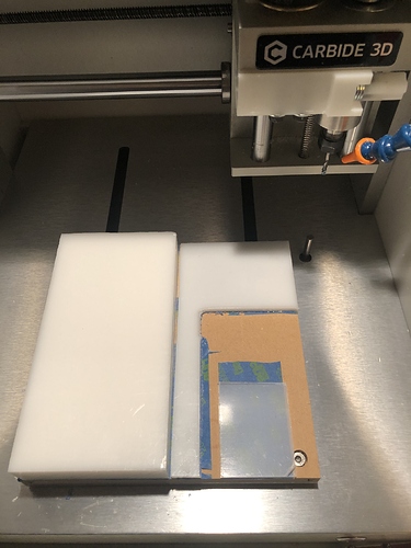
#3 - If you tend to use the same materials time and again, always keep some strapped to your wasteboard.

The Nomad space is limited and I tend to divide the table up into 4 square ‘zones’. Unless I have something specific I will order or cut stock to 4”x4” and 4”x8” blocks. Each material gets placed in a free ‘zone’ around the wasteboard. This allows me to nibble away at each material as need arises without having to carefully tape/glue/square stock every time I go to mill something out. Usually keep one zone open for whatever odd or end comes up.

If one gets clever you nibble over the screw holes first (though some day I may experiment with smaller or not quite square shaped stock in each zone) thus being able to swap from one populated waste board to another.

Does this always work out? Not necessarily. But on those days where you need to deliver fast it saves mounting/waiting to dry/prying off chunks of stock.

3 Likes