Thank you! I’m a “house divided” - one daughter went to Arizona State and the other to University of Arizona.
1 Like
Silly me was worried, but not anymore!
Awesome, awesome entries…
1 Like
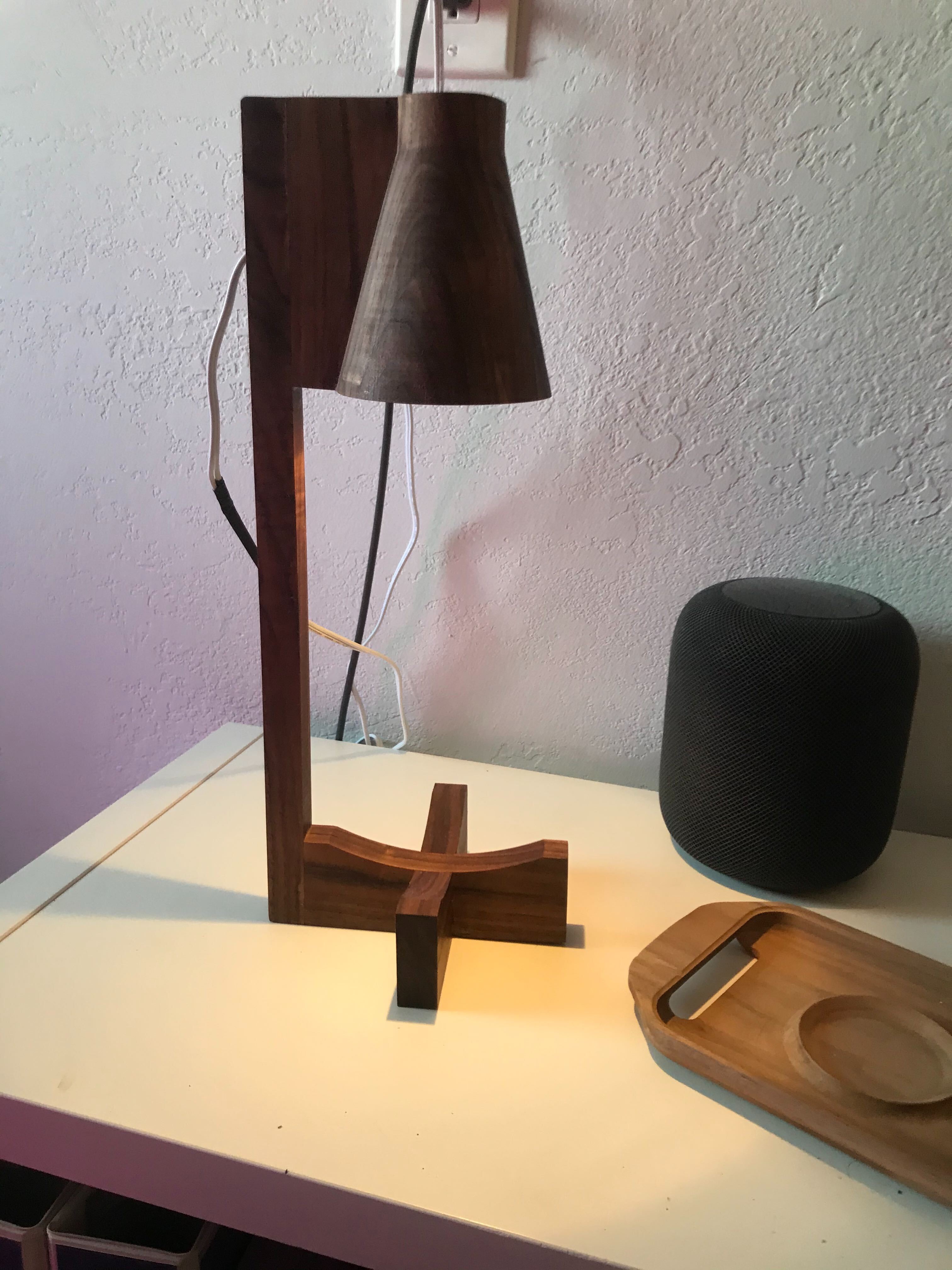
Walnut Lamp!
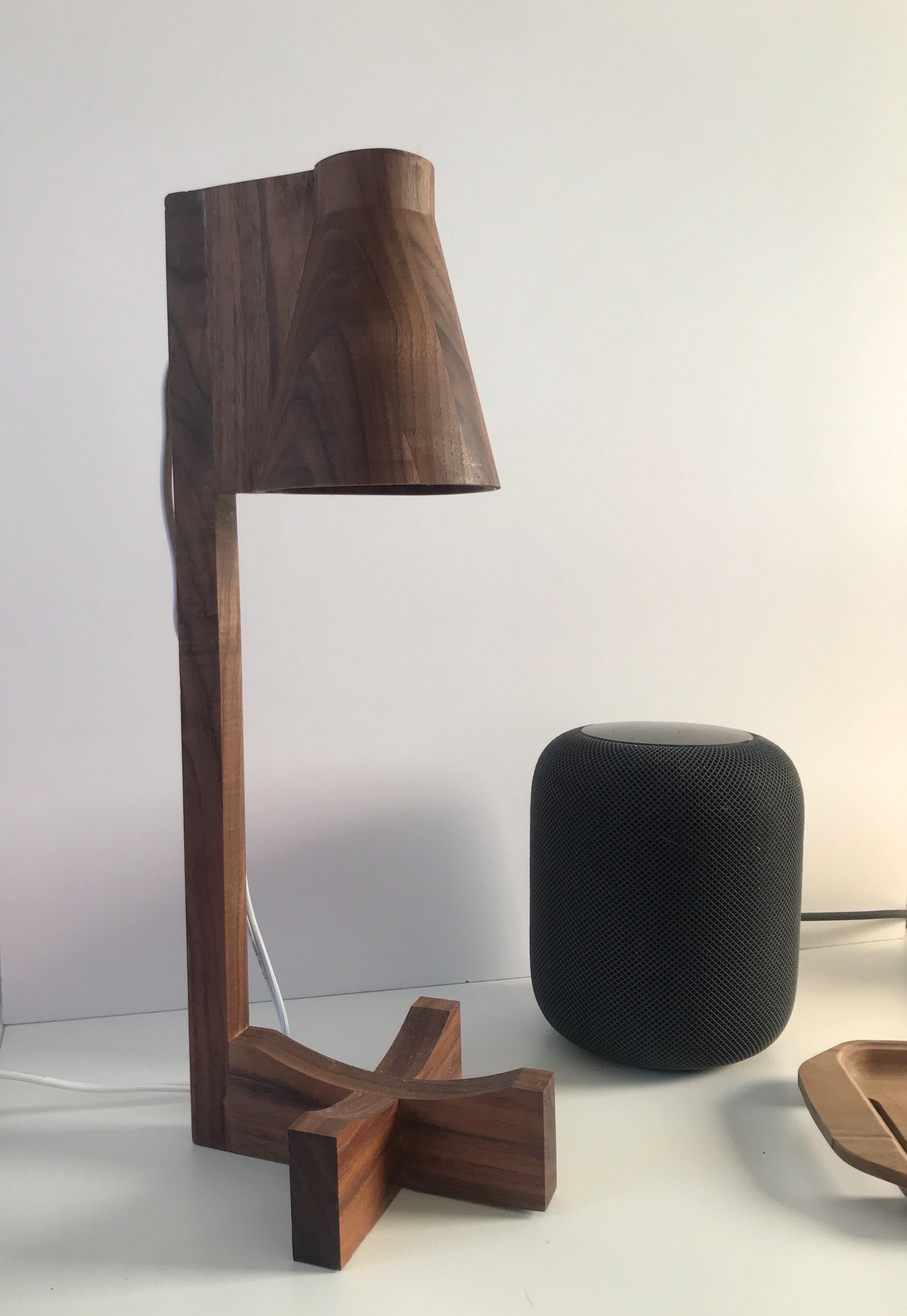
I designed this geometric / mid-century modern lamp, which turned out to be quite the challenge to mill.
I have wanted to make a solid shade like this for a while now, so here we go…
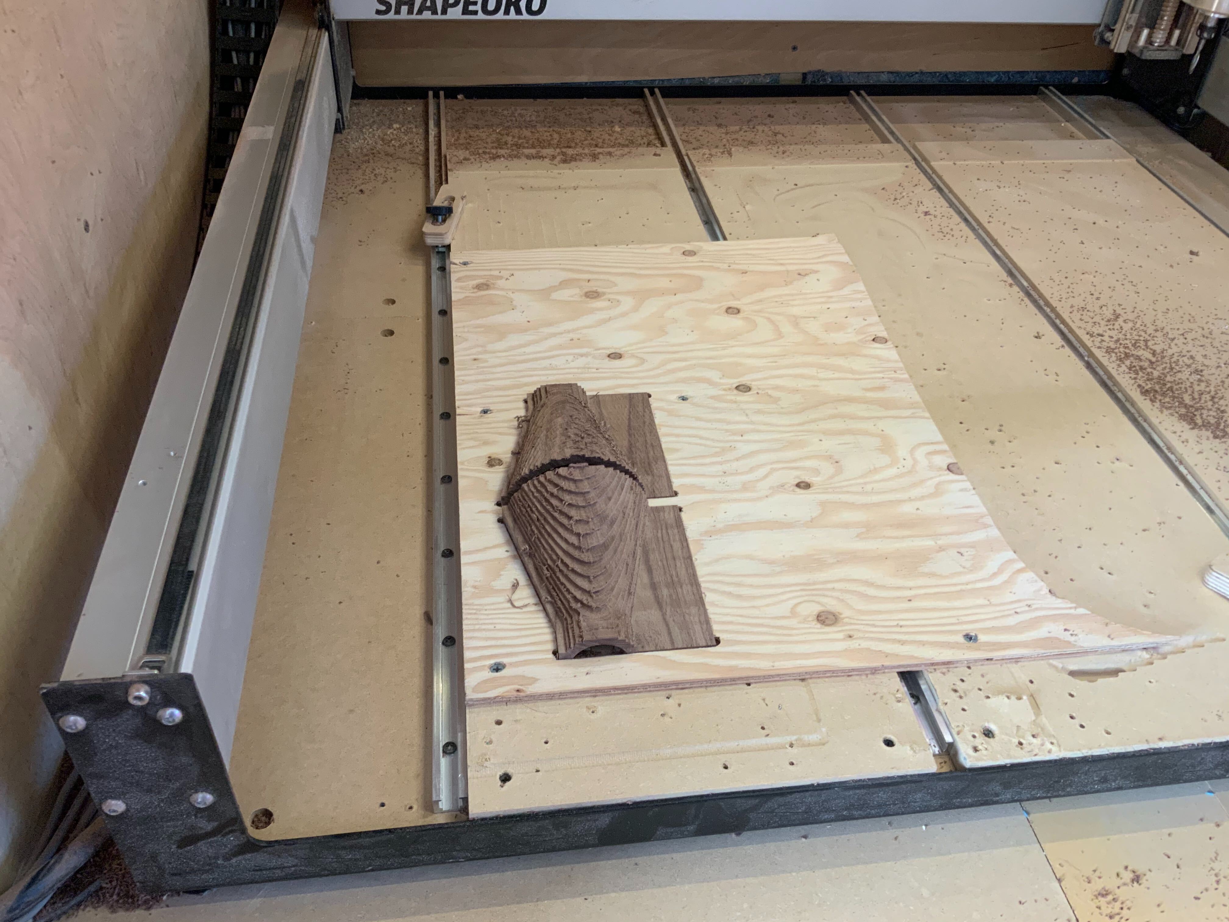
This entire project could be categorized as figure it out as you go. I glued up this block before I fully knew where I was going, so I had a little more stock material than I needed. Lots of wood Chips!
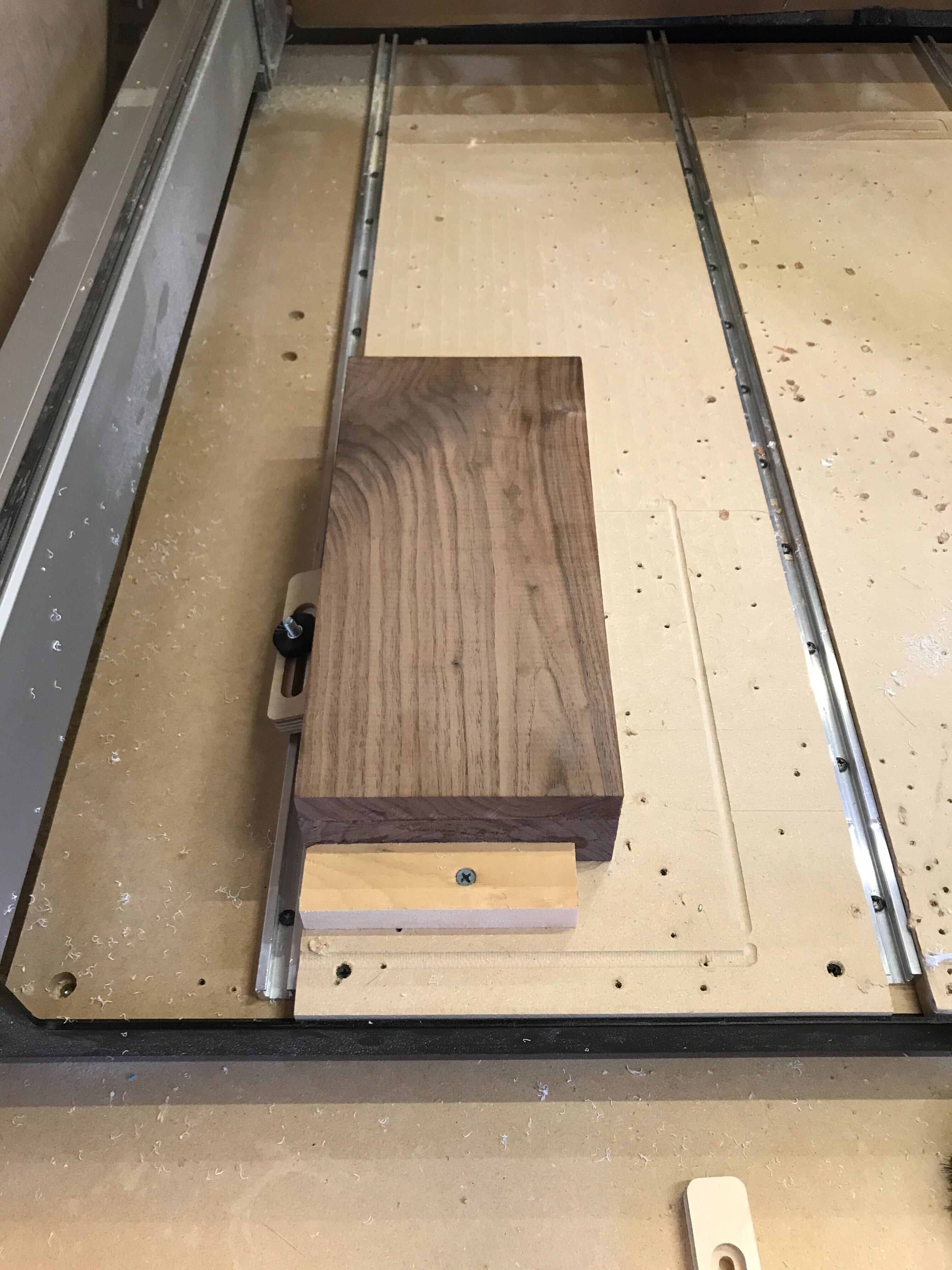
First side was the inside of the shade. I added some slots that would latter act as a way to attach the shade to the vertical and give me a place to route the cord. After milling the first side I realized I left no material to fixture after the flip.
 So I milled a quick pocket in some scrap wood to locate it on the machine and hold it in place along with some double stick tape.
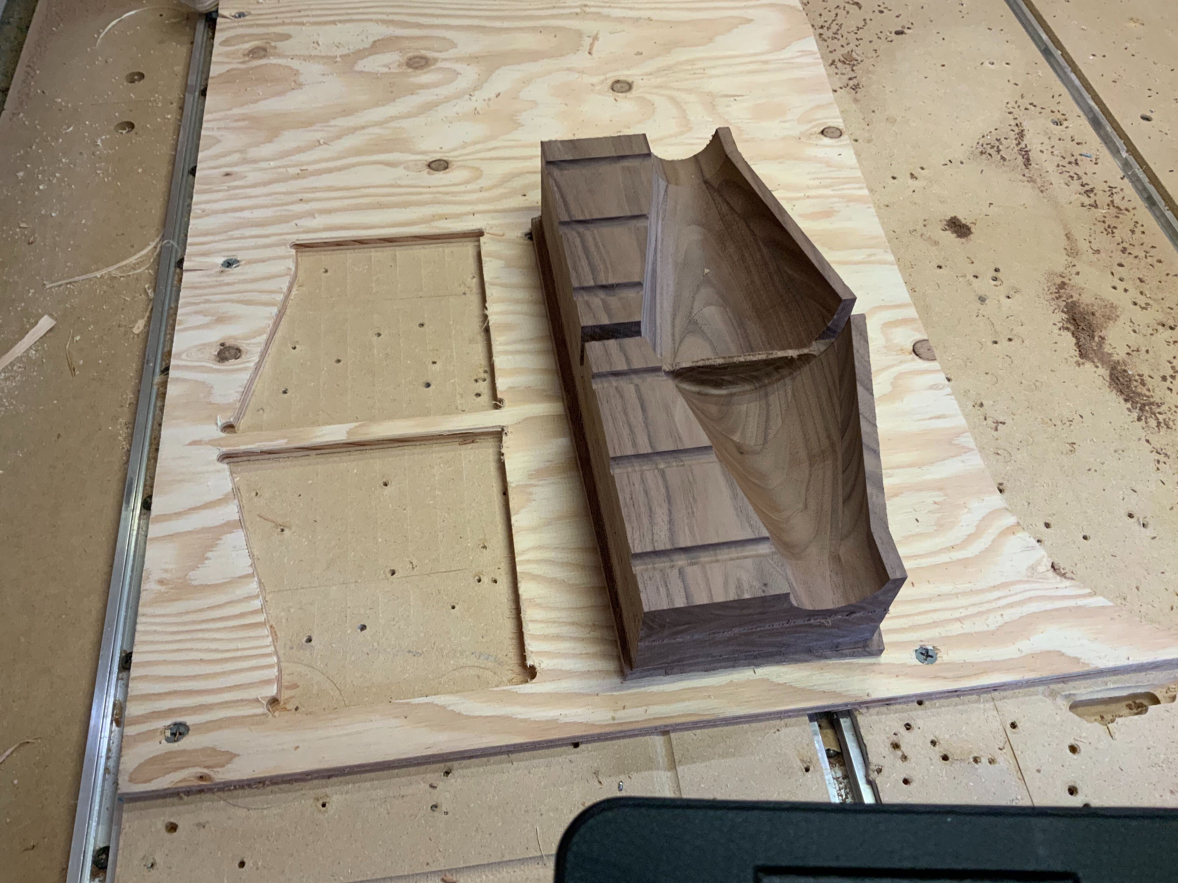
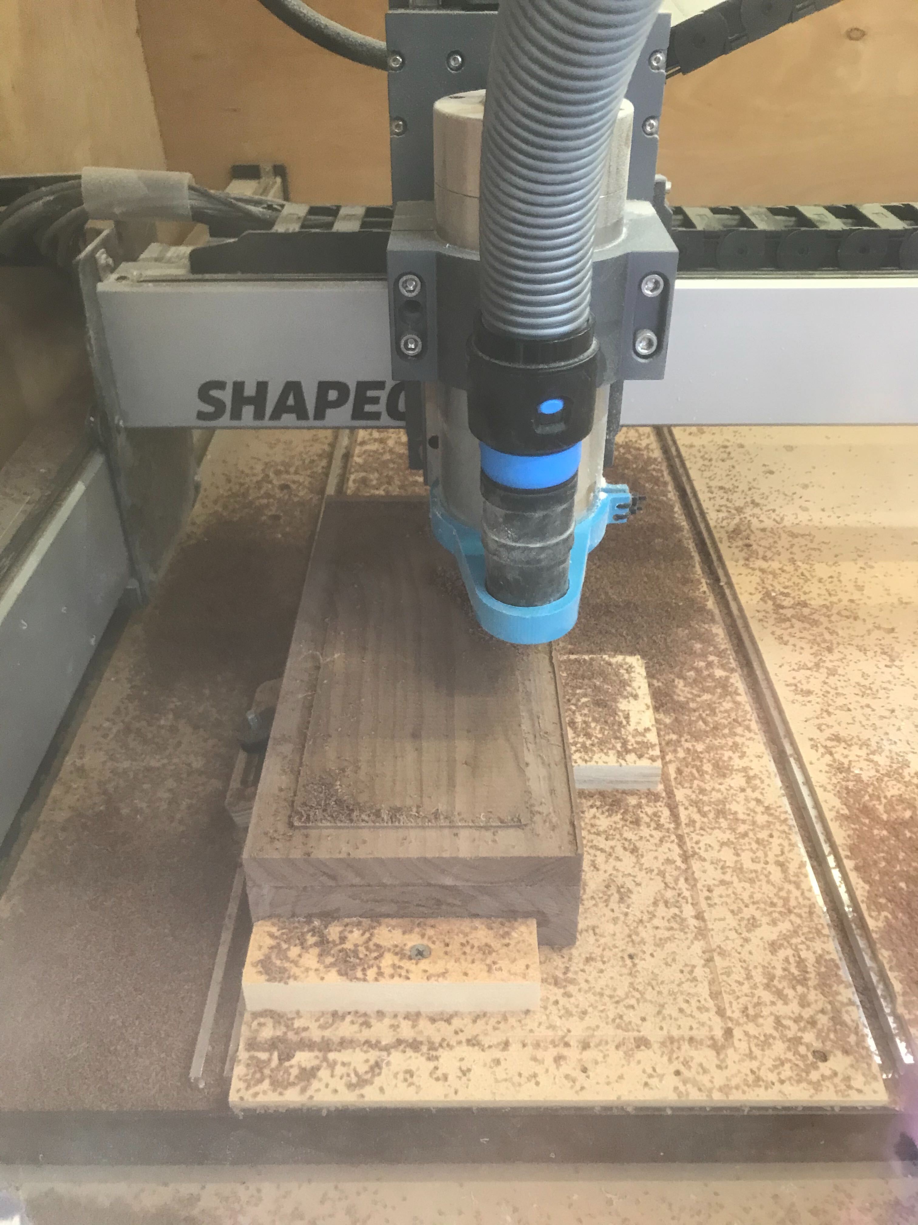
Second Side:
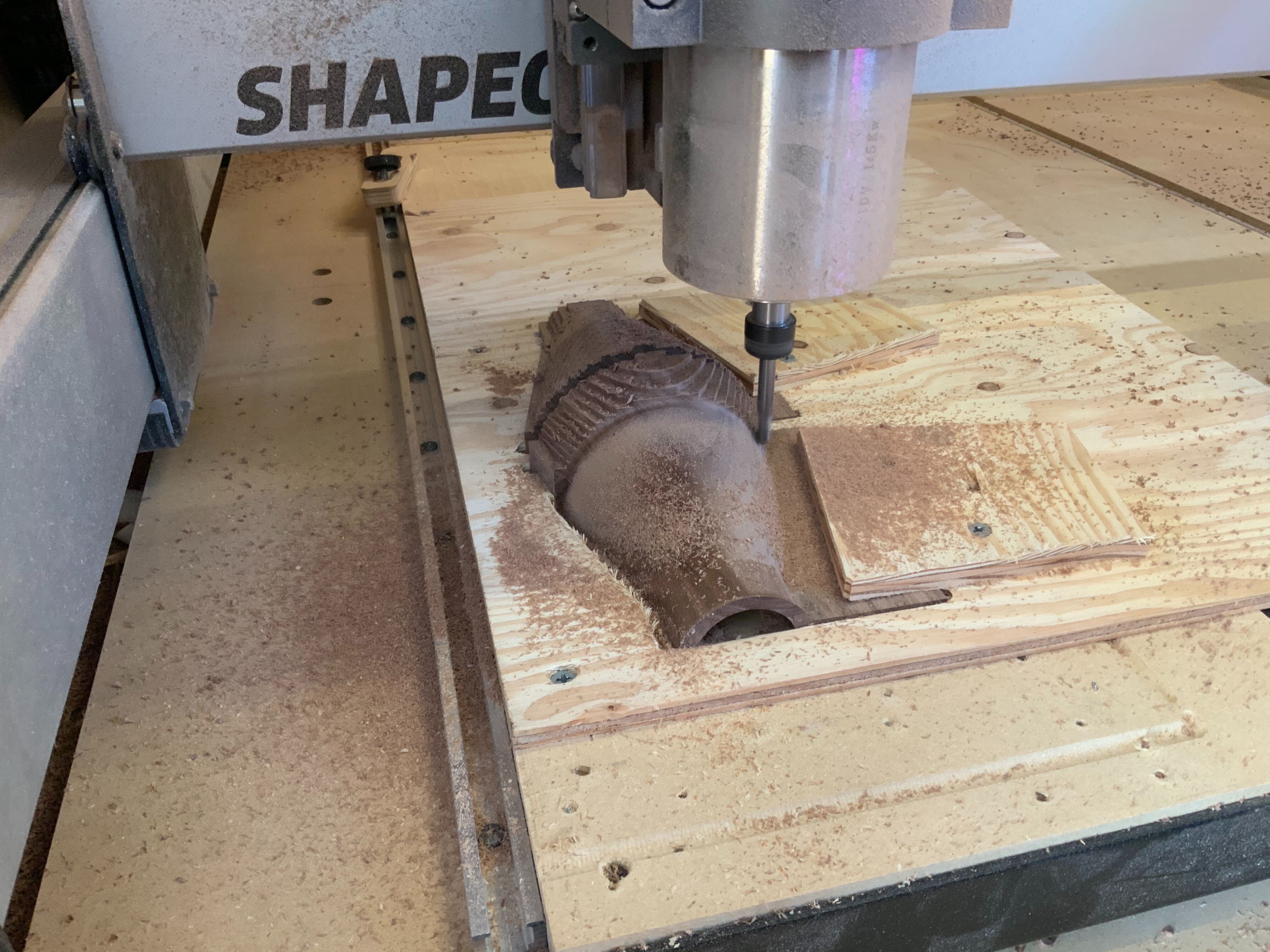
The double stick didn’t quite hold through the roughing so in finished the flat parts and then clamped them down with some more scrap wood.
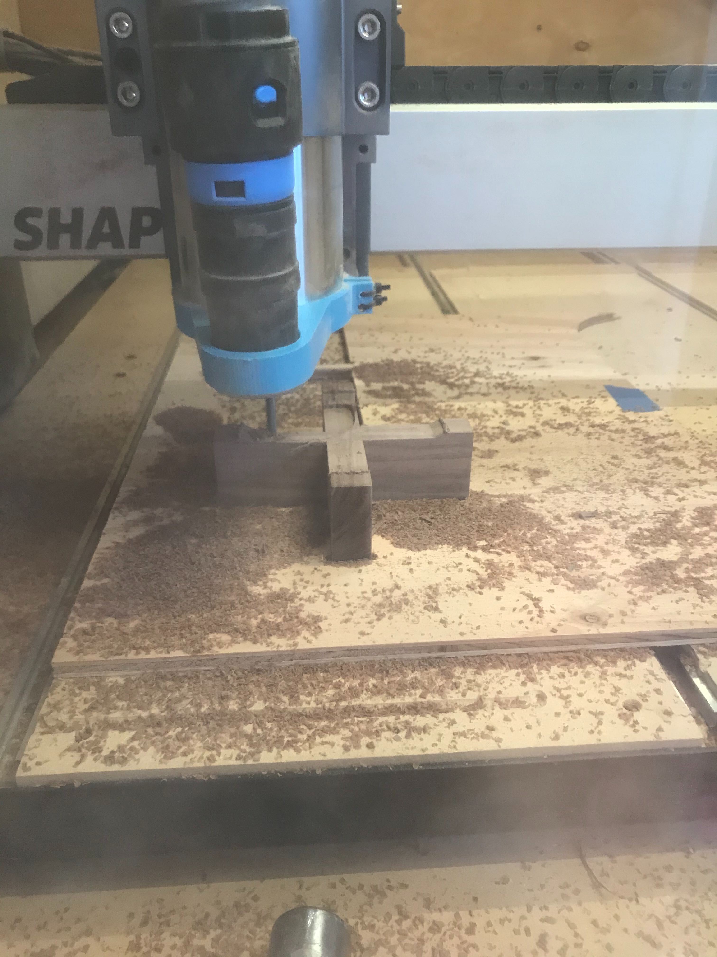
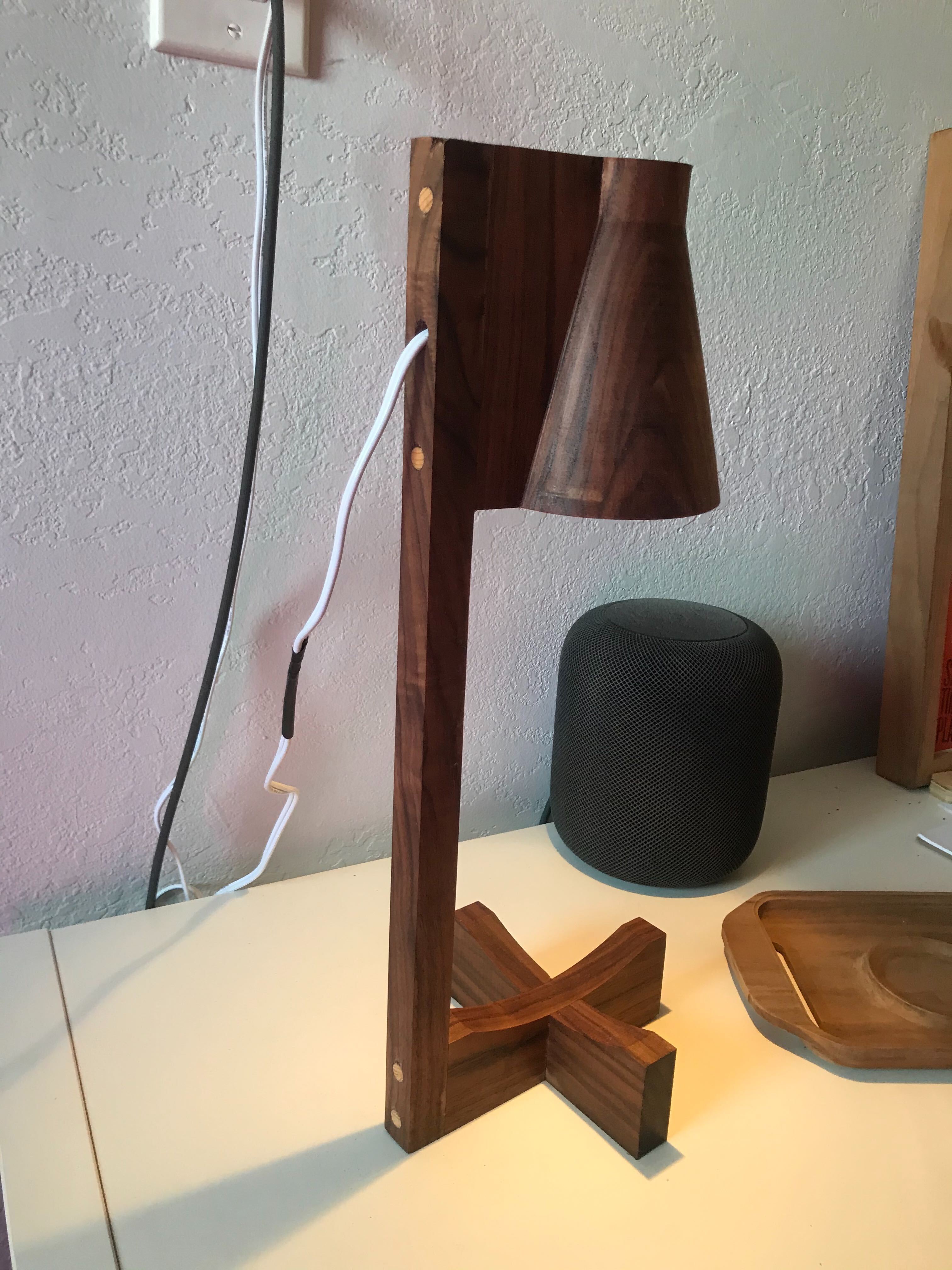
For the Base I cut 2 slotted pieces and glued the together. I wasn’t totally happy with what was basically two crossing rectangles so I put it back on to add a curved feature to the top, that may later hold a tray for keys and coins.
The vertical was next, a quick rectangle contour with drilled holes to attach the base and the shade (forgot to get a picture ). Then glue and clamp with locating help from the holes that where drilled/ milled and some dowels.
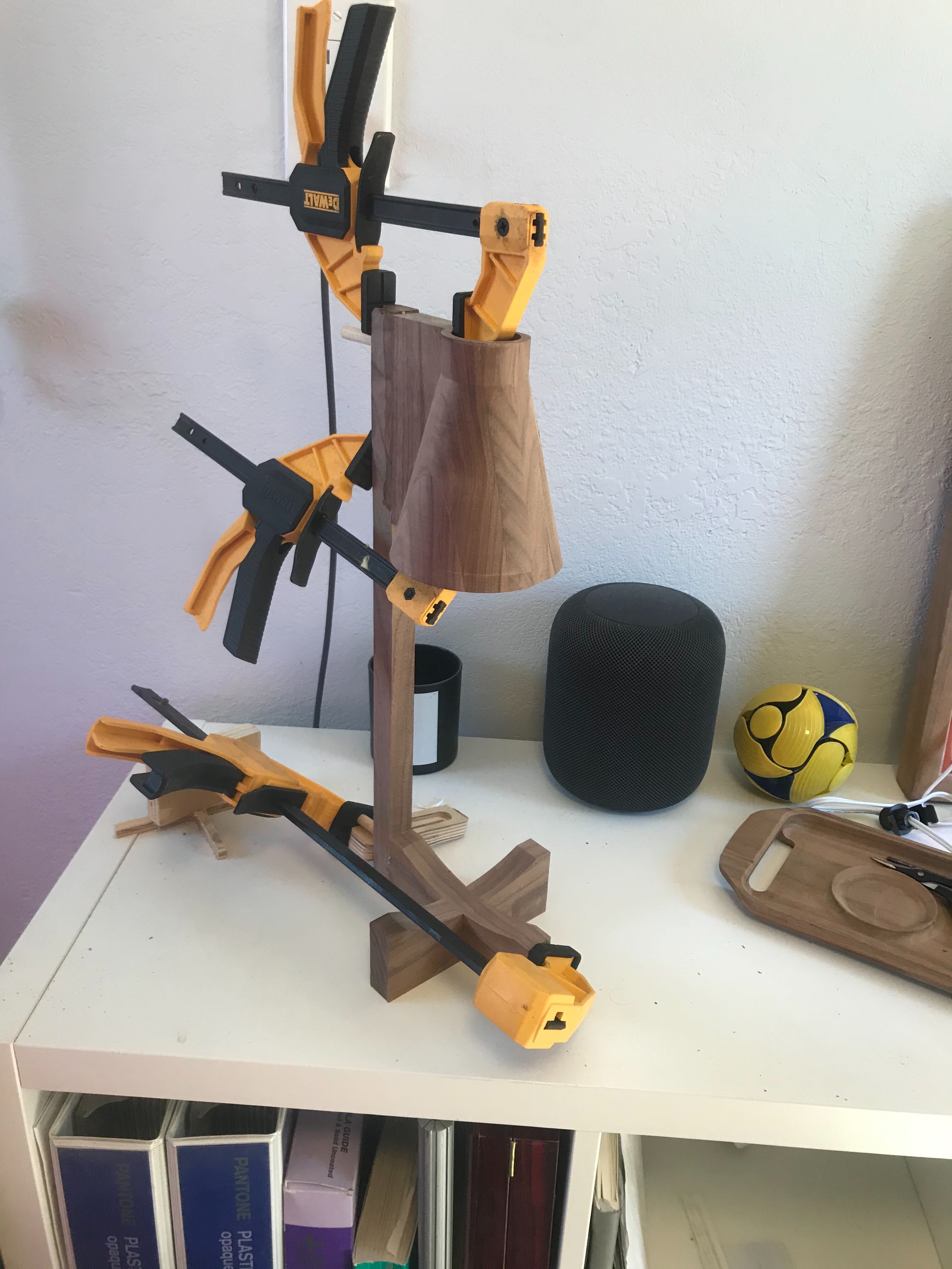
Lots of hand sanding then voila:
Would love some suggestions for better ways to handle the flip. there are few design changes I would make, so I might try this again.
Here is the CAD file.Walnut Lamp.stl (162.7 KB) https://a360.co/3cCNEJ9
cut rocket: https://cutrocket.com/p/5f70b6cc67d1a/
Thanks for the challenge, and for checking out my project!
12 Likes
There is this Philips Hue Go lamp… 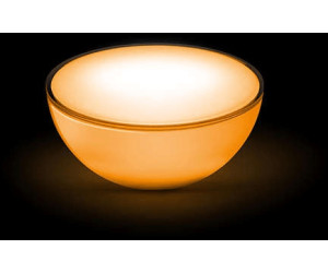
… which I find nice to wake me up in the morning, but otherwise I find its feasibility somewhat limited. That’s because you put it on the floor/table/whatever and it lights from the bottom up, blinding you or not effectively lighting the room.
So thanks to this challenge I came up with the idea to extend its field of use:
Final product
-
Use it as a down-facing lamp
-
Use it as an up-facing lamp
-
Use it as a lantern (up- and down-facing)
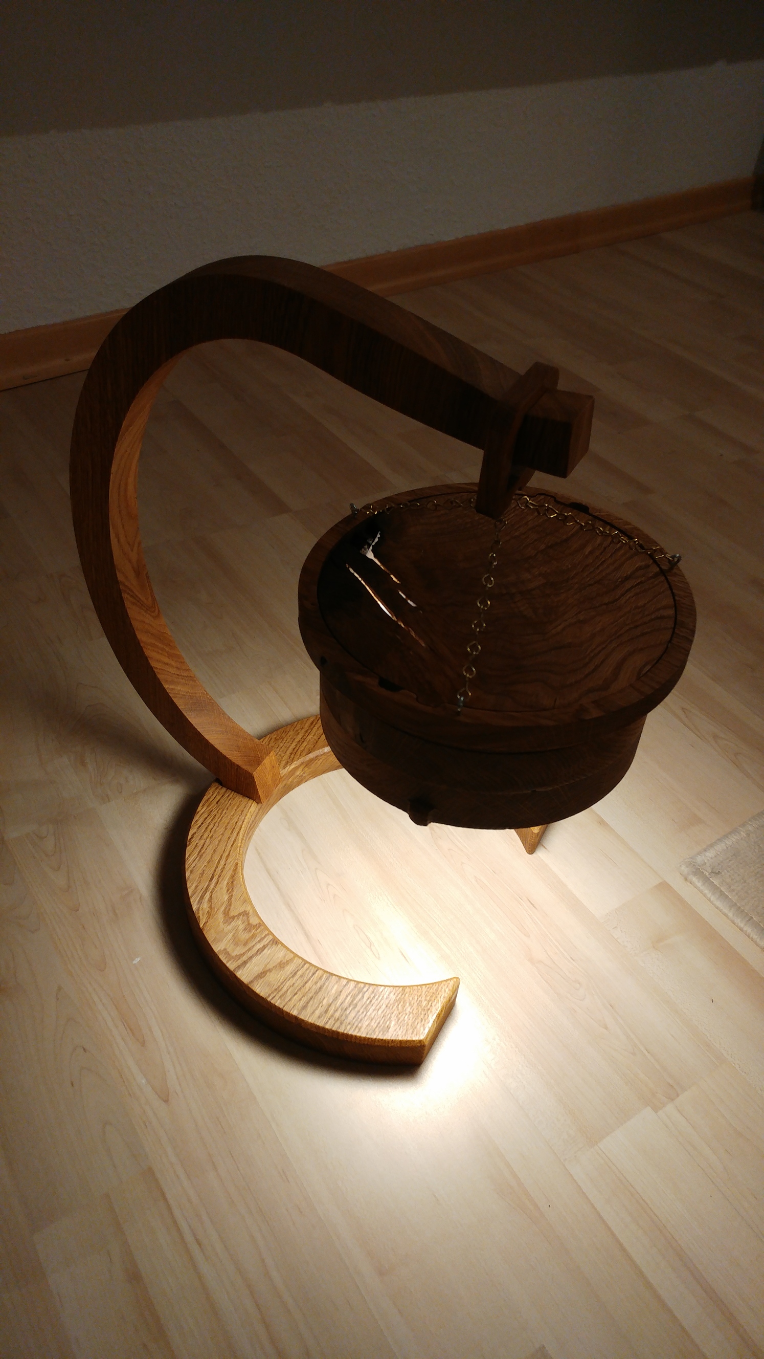
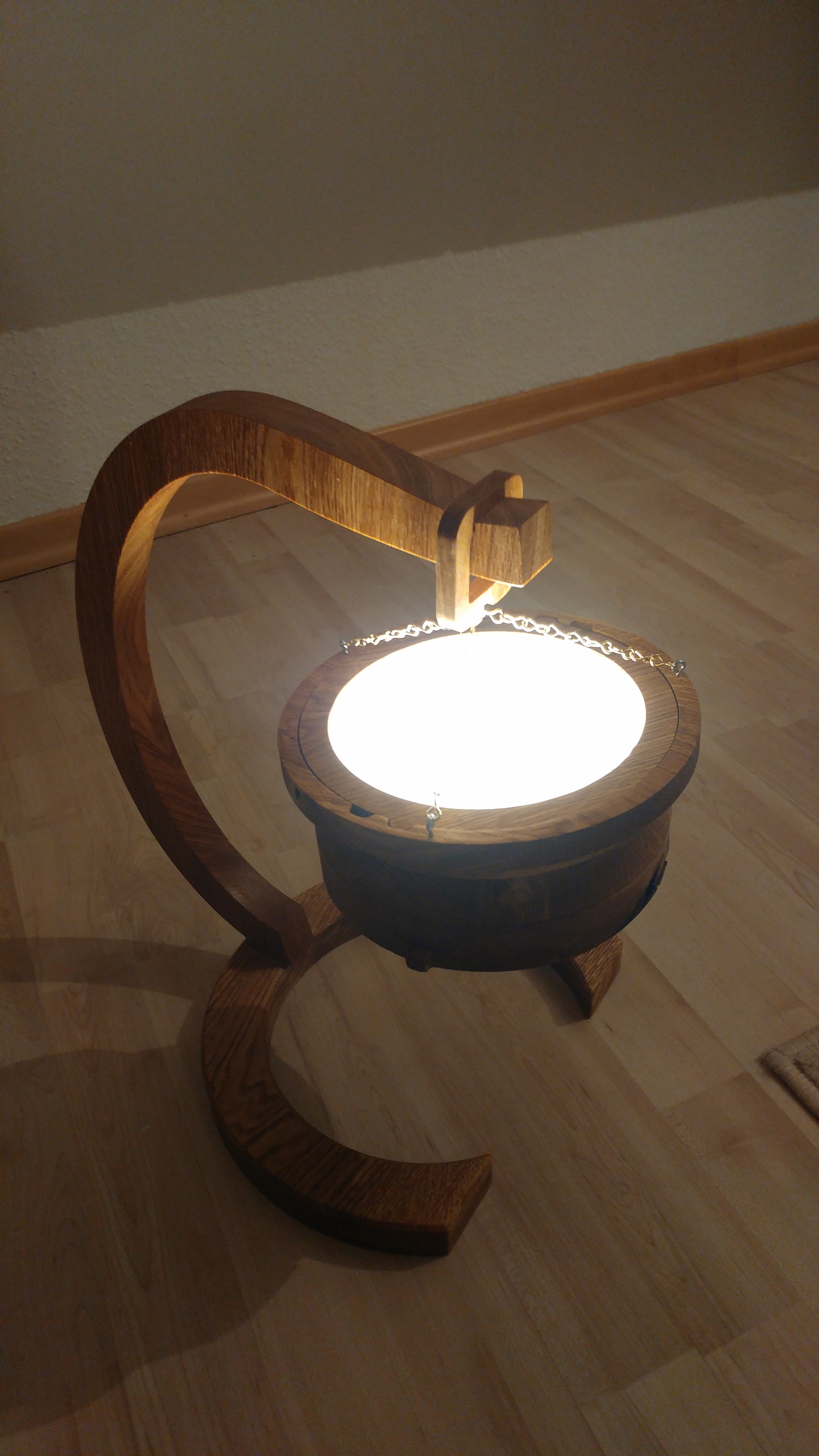
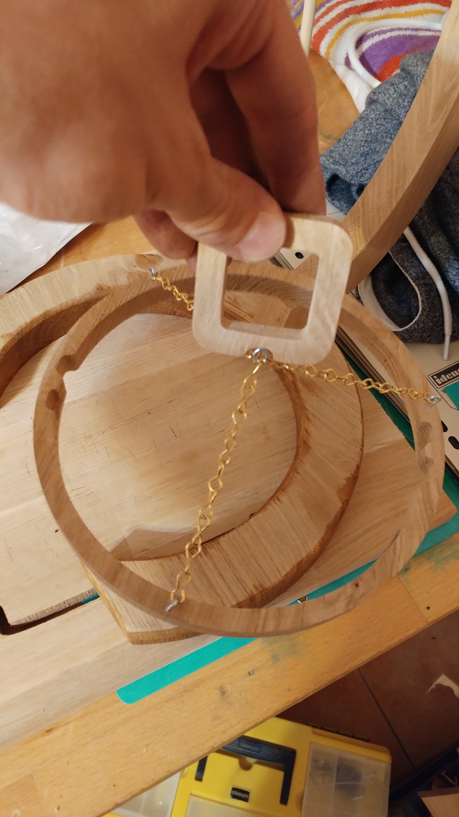
The stand without the actual lamp looks like this:
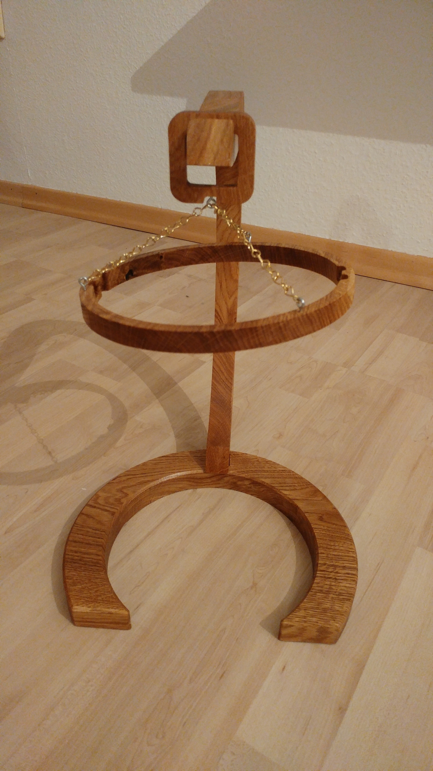
It has a foot/stand and a ring hanging onto that.
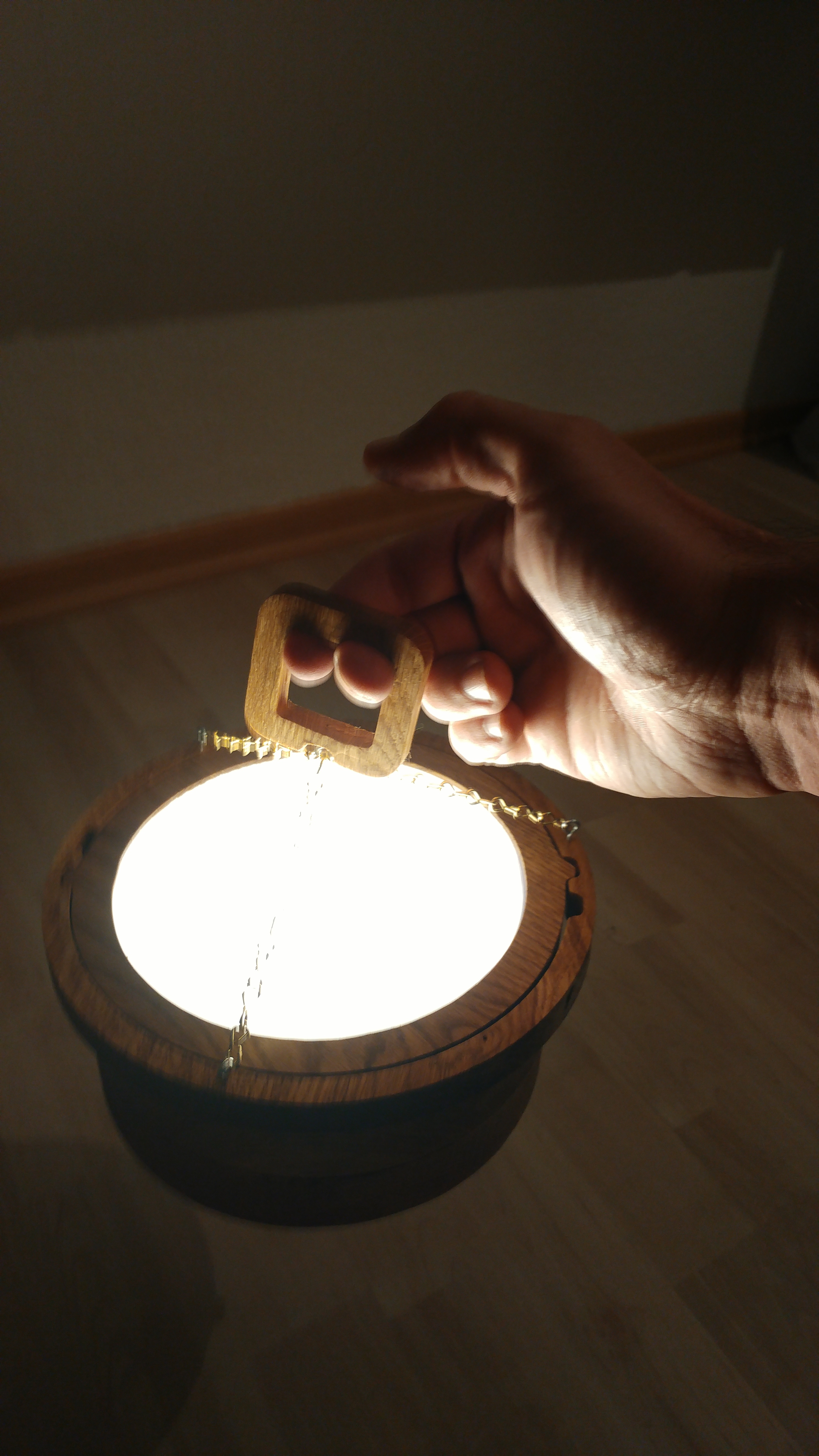
You then put the Hue Go into either of the cylinder parts (
which can be assembled via magnets)
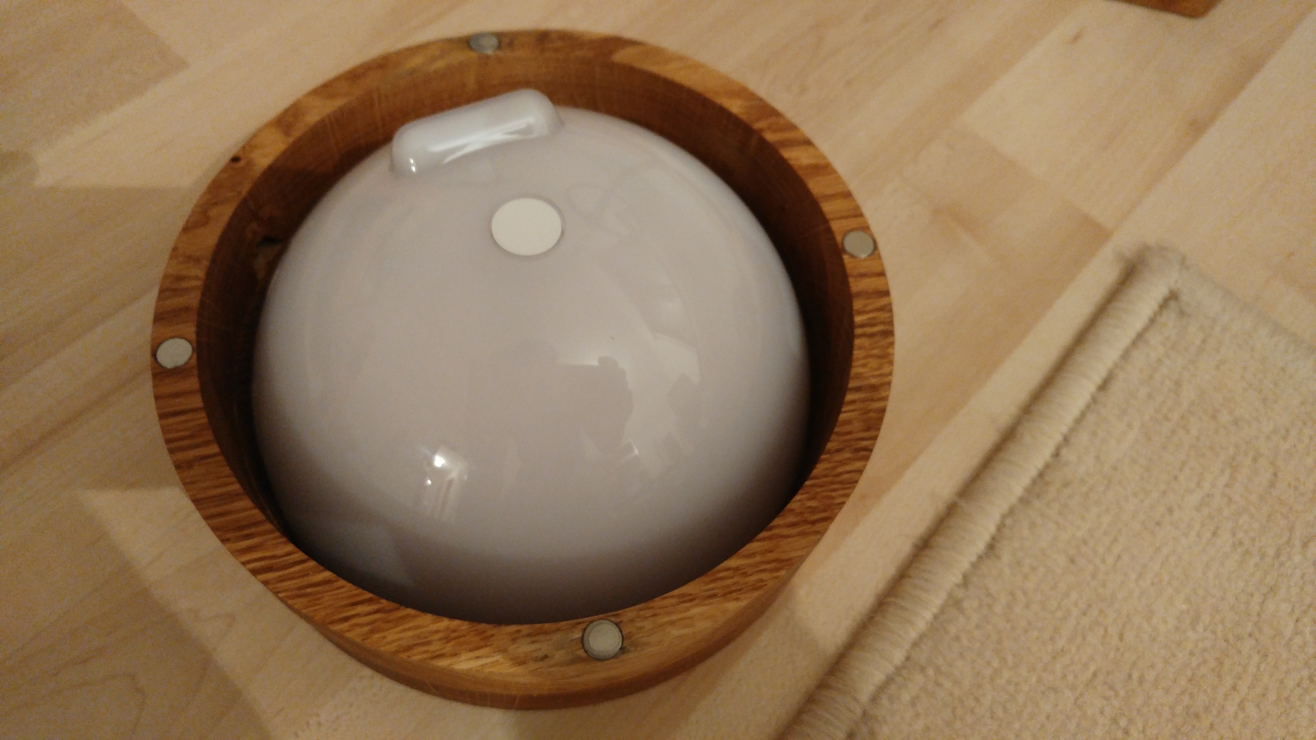
and snap the other part into the ring on the stand. So by choosing to snap either one of the cylinder parts into the ring, you can have the opening of the cylinder at the top or at the bottom.
So far the Hue Go can be used with its battery only. I’ll have to figure a discreet way to attach the power supply.
Process
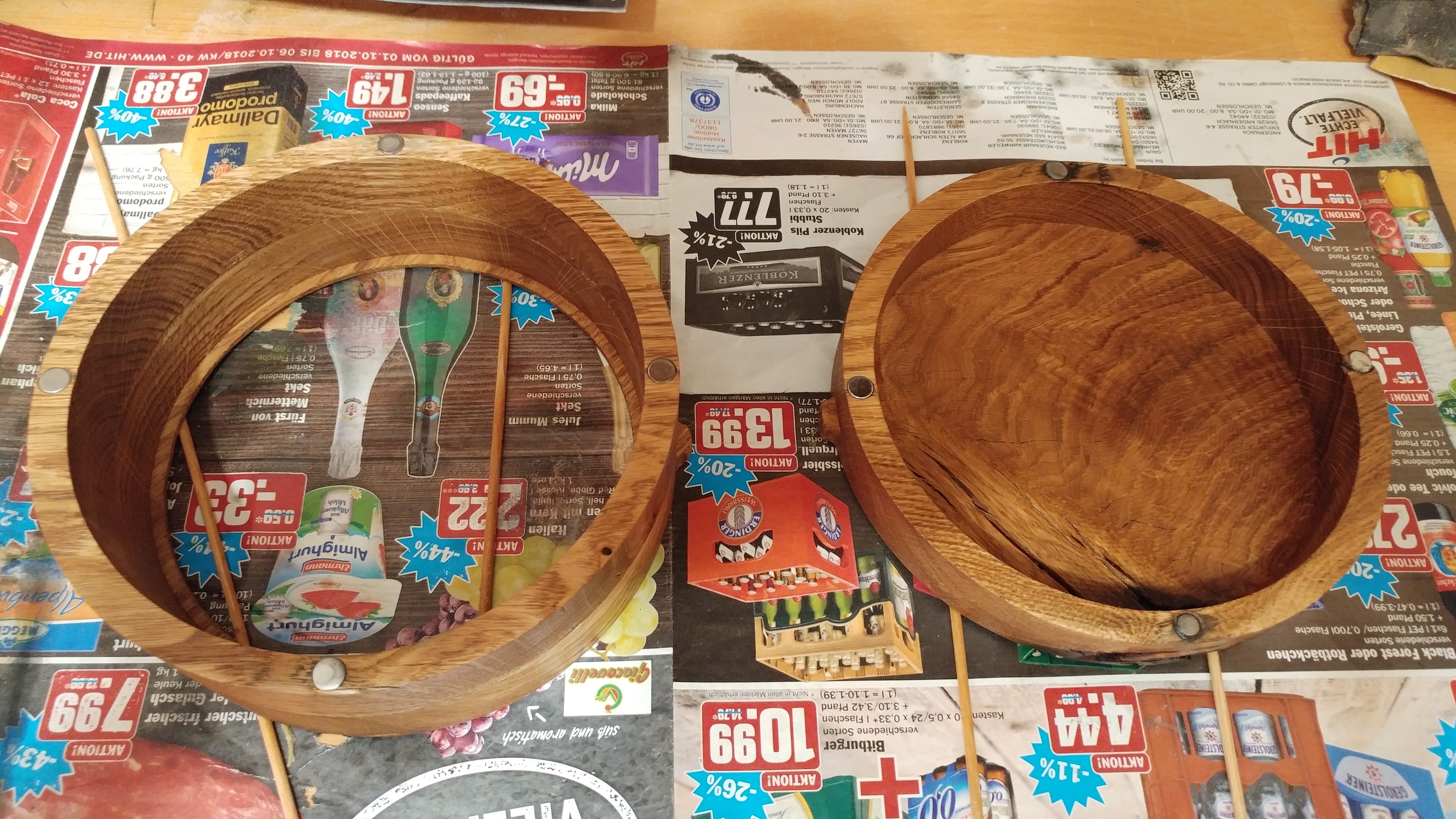
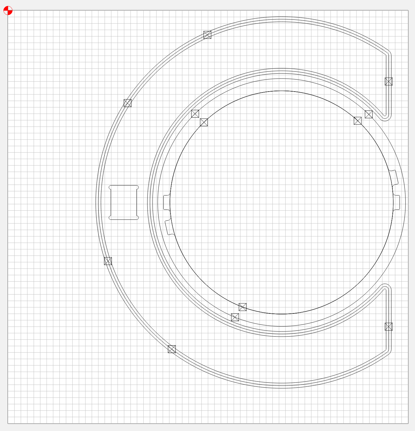
The cylinder where the lamp goes in is assembled from three rings:
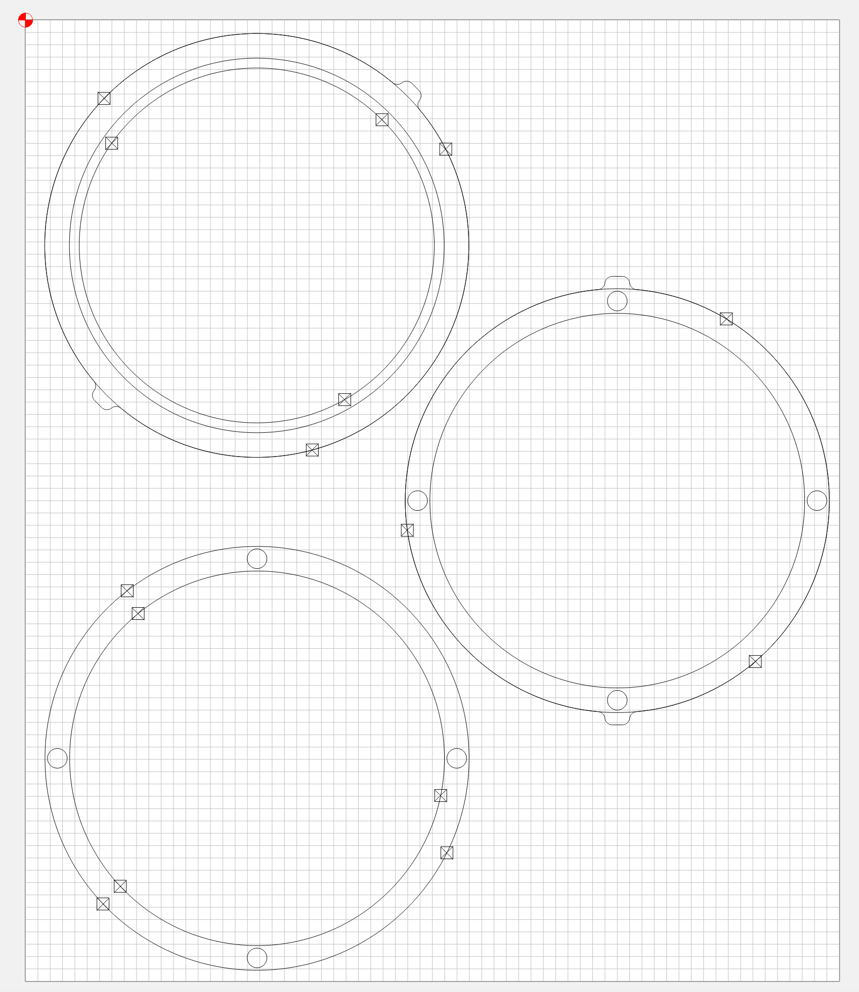
The small circles on the edges of the two lower rings are the pockets that hold the magnets, that allow to oben the cylinder and access the Hue Go.
The noses on the upper two rings will be used to snap the cylinder to the ring on the lamp’s arm.
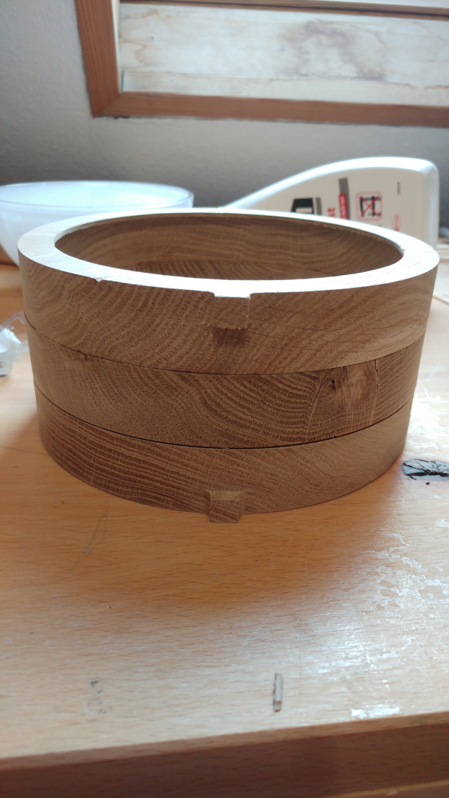
The upper two rings get glued together and the third ring will be attached via magnets.
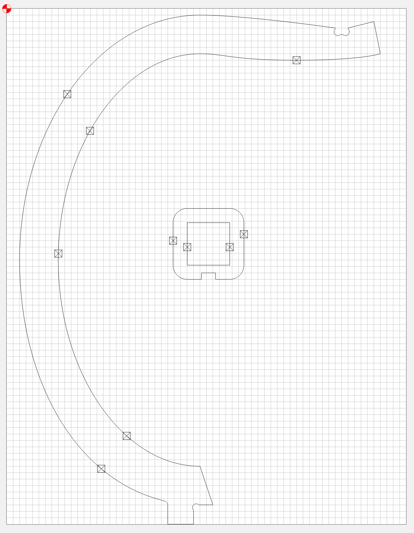
The foot of the lamp has a C-shape and here you see the additional ring where the cylinder can snap into.
Finally there is the arm of the lamp and a small piece that helps to hang the cylinder onto the arm.
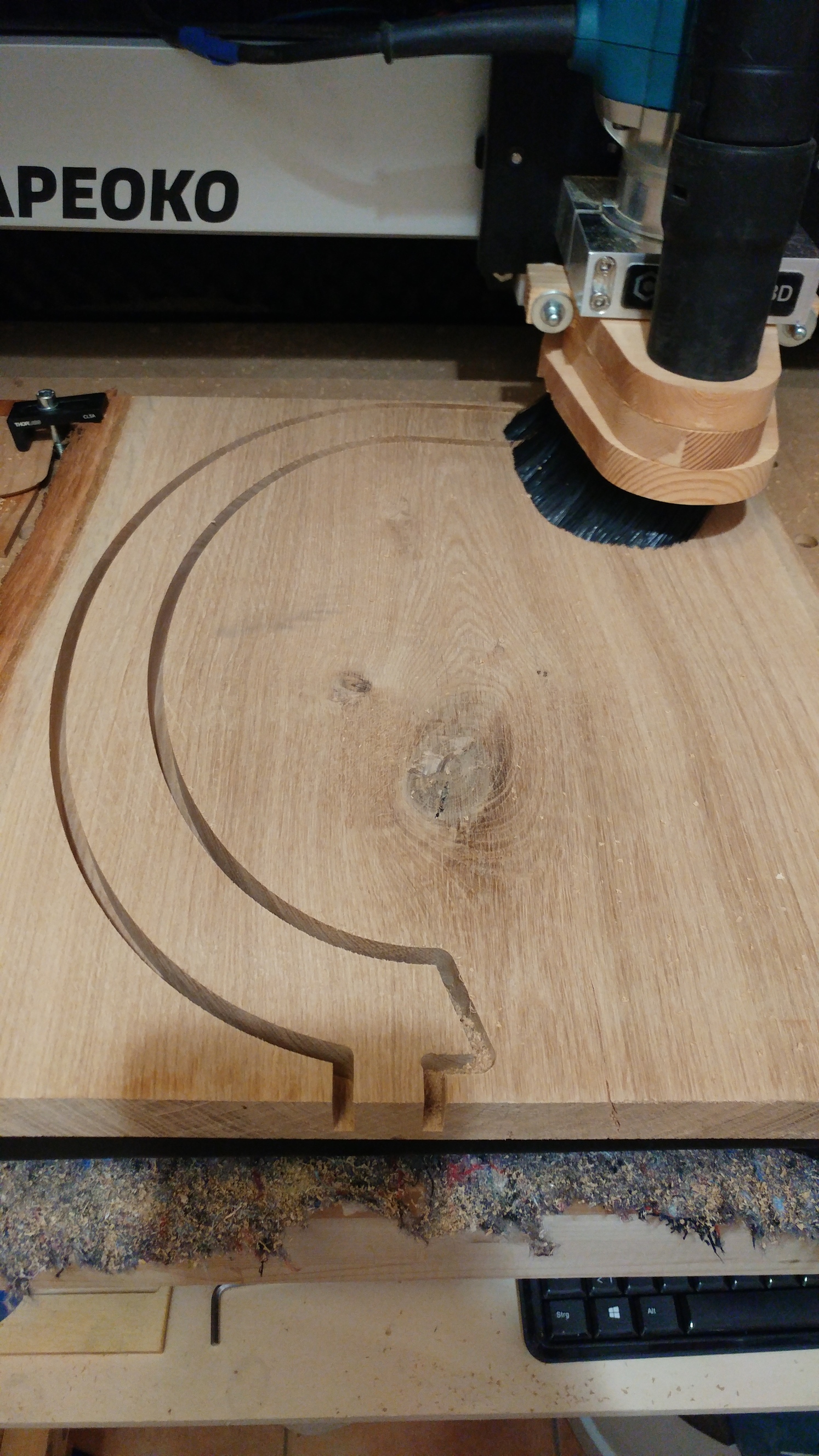
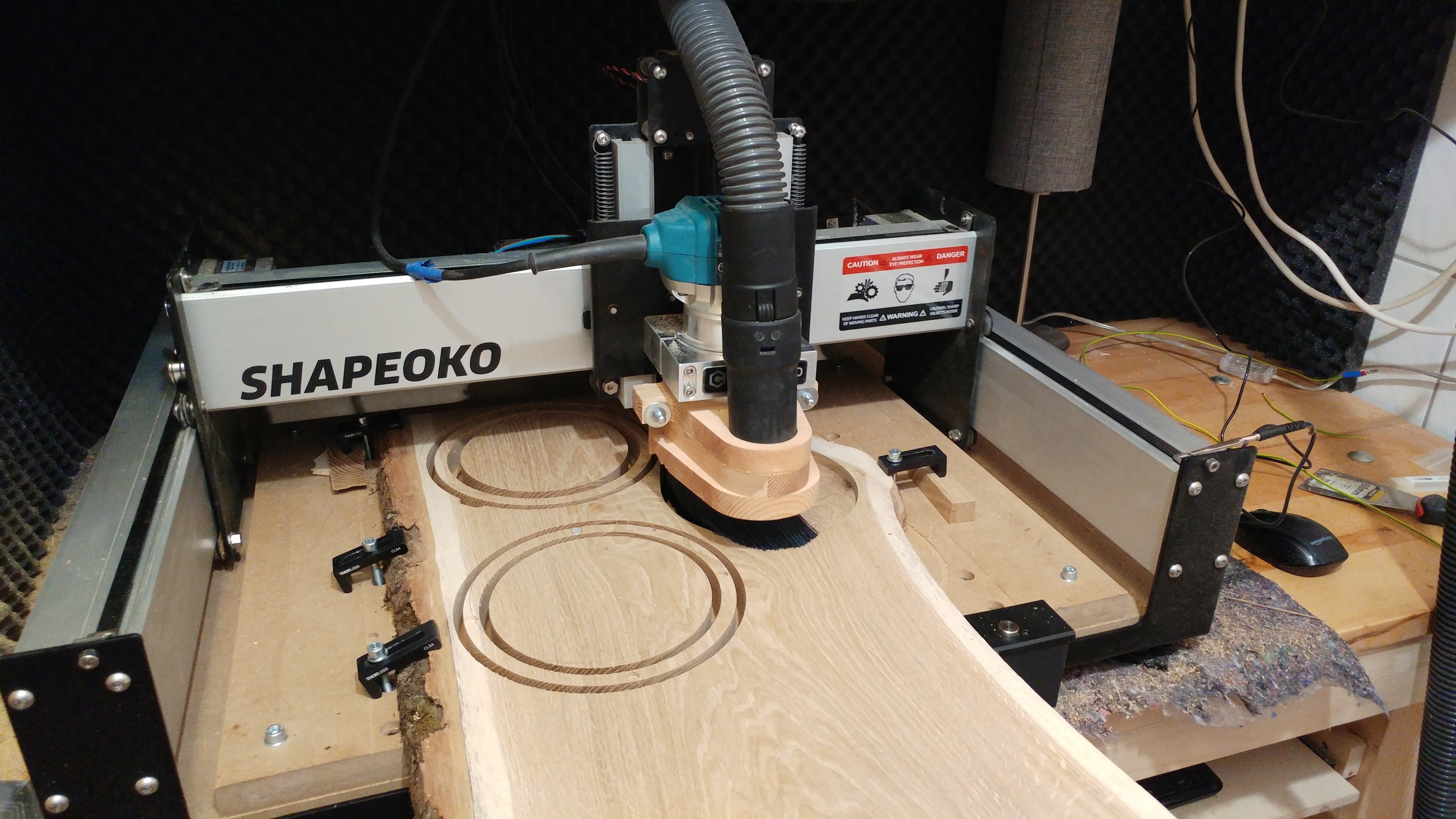
Everything was cut from 26.5mm oak with a 6mm end-mill. Only the pocket in the foot part was cut with a 3mm end-mill and the foot got a 90°-v-carved edge.
The fitting of the arm and the foot did have a little too much play, even though I designed the fitting parts with no extra space. What’s you guys’ approach when designing parts that should fit tight? I wouldn’t deny the possibility that my machine’s steps are not properly calibrated 
Magnets
arm.c2d (382.1 KB) cylinder.c2d (1.7 MB) foot.c2d (1.7 MB)
11 Likes
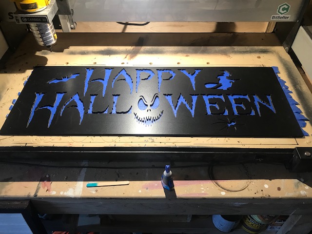
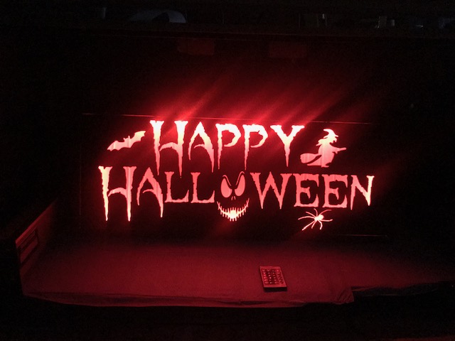
Halloween Yard Lamp !
Pretty simple design for our Daughter. She does serious Halloween Yard Art.

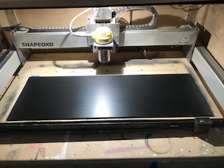
Designed it all in Carbide Create and used Carbide Motion to cut.
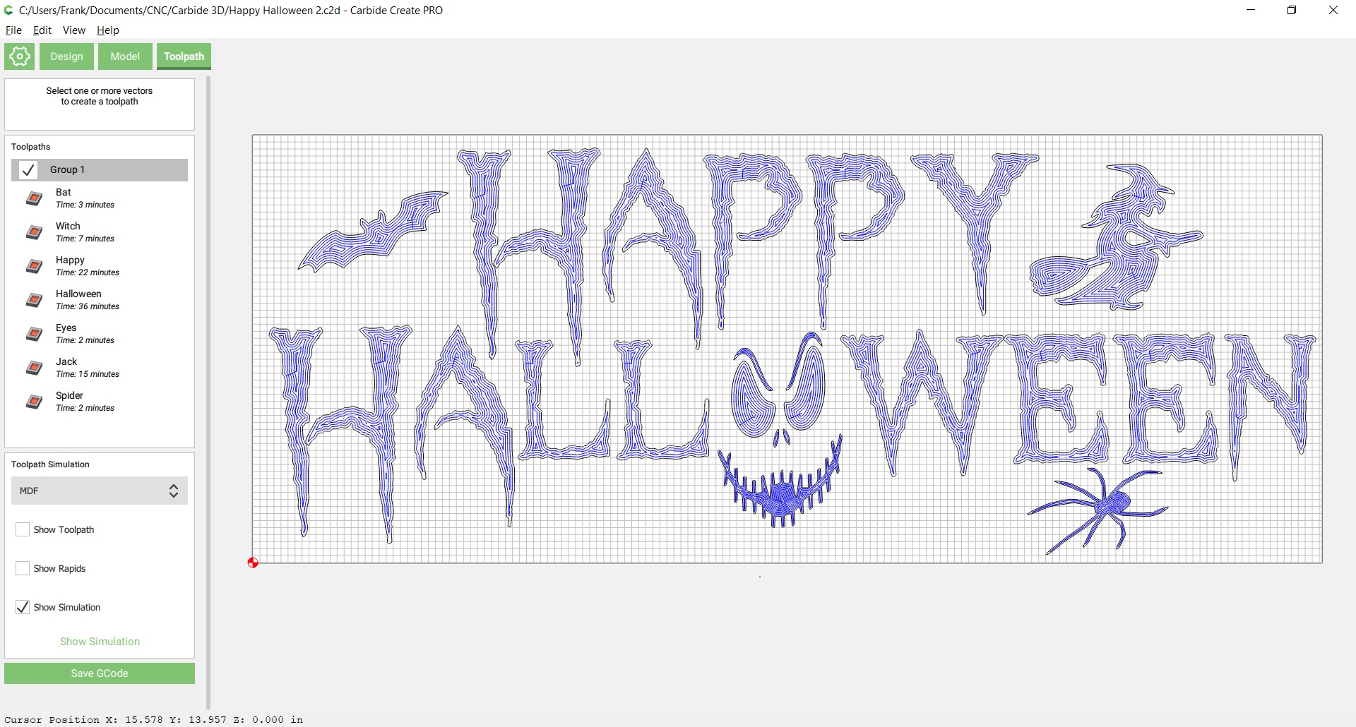
Started off with basic black plastic sheet, 1/4 inch thick
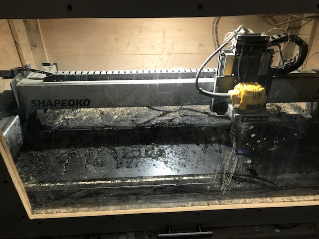
This stuff is a mess to cut !!! Time to buy a vacuum system.
But using pocket cuts with as small as 1/16th in, got some good details and sharp edges.
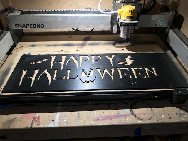
Prepped the back with blue tape and filled in the sign with clear resin.
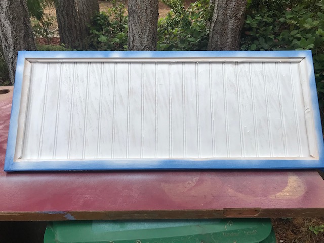
Built a simple plywood box and routed out 1X pine strips to let the sign sit in a recessed frame.
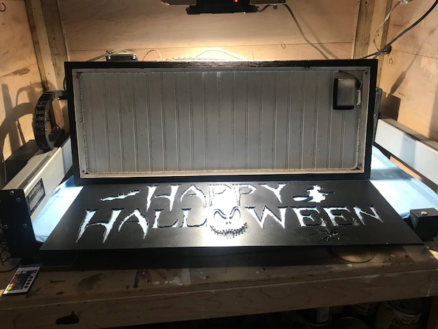
Final Assembly after a dark walnut stain on the outside
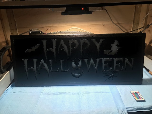
Set multi-colored led lights around the inside edge and button magnets in each corner to hold snug in the frame. Can’t upload a movie so here is a small sample:

Design and cut files
Happy Halloween 2.c2d (1.3 MB) Halloween Sign.nc (1.6 MB)
and Cutrocket page
Be safe out there everyone!
9 Likes
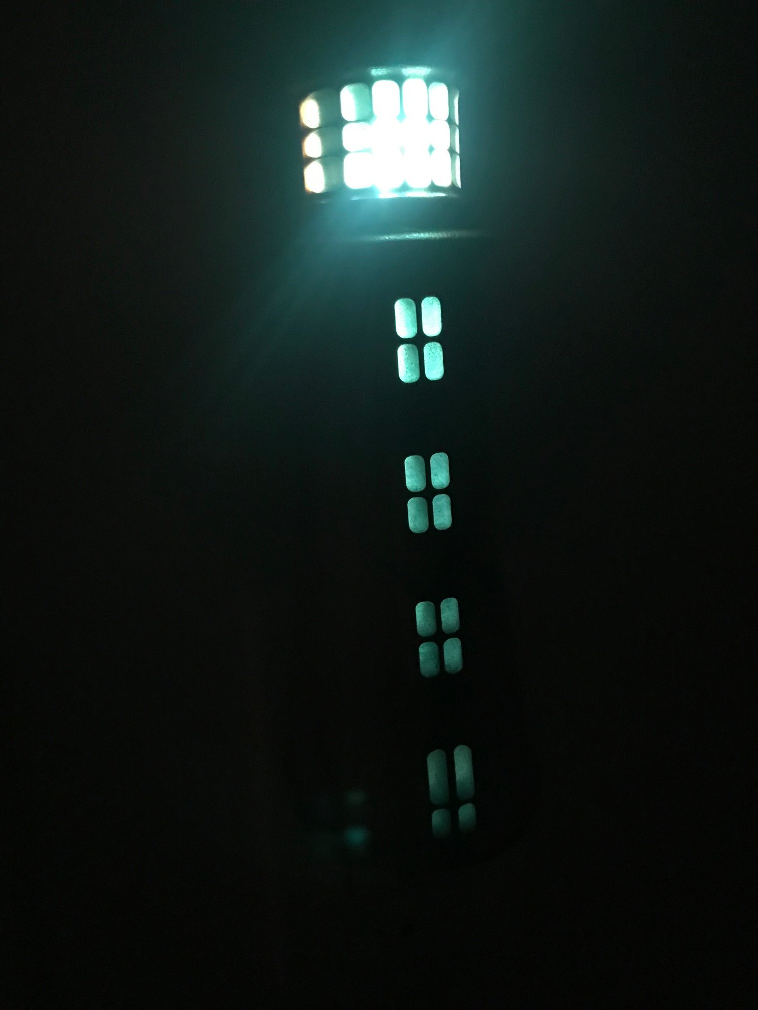
I’ve been wanting to make a lighthouse nightlight for some time now. Thanks to the motivation of Carbide 3D and @Julien, I’ve finally managed it!
I bought a couple of variations of inexpensive nightlights from the big box home improvement stores. In this case $2:
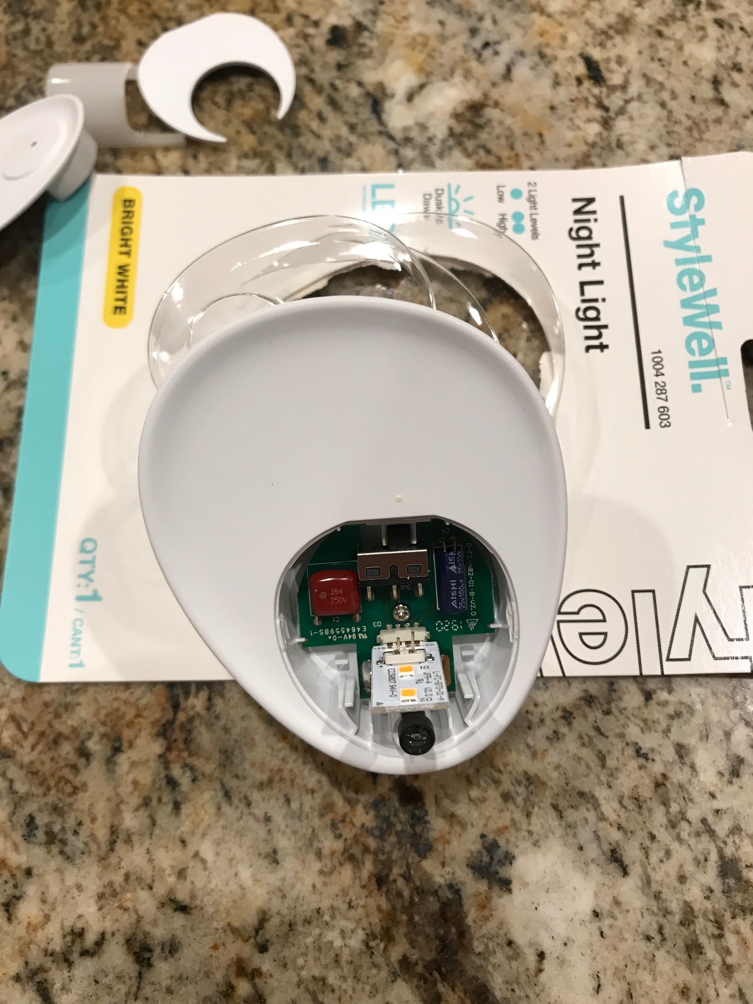
Yep, it’s full of Voltaic Voodoo in there. However, this saved me from gathering parts I don’t understand from several different sources.
I designed and generated all of the toolpaths with Vectric Aspire. Just haven’t gotten a handle on Carbide Create Pro or Fusion 360, yet. All of the cutting was done with Carbide Motion This is my artwork, so all are welcome to use as they see fit.
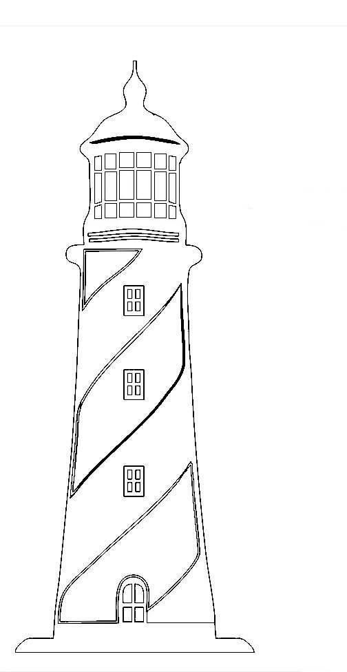
LighthouseNight Light.dxf (100.1 KB)
I did modify it somewhat into the DXF image for this project hoping to get the windows to work out with a 1/8" end mill, which I’m pleased with.
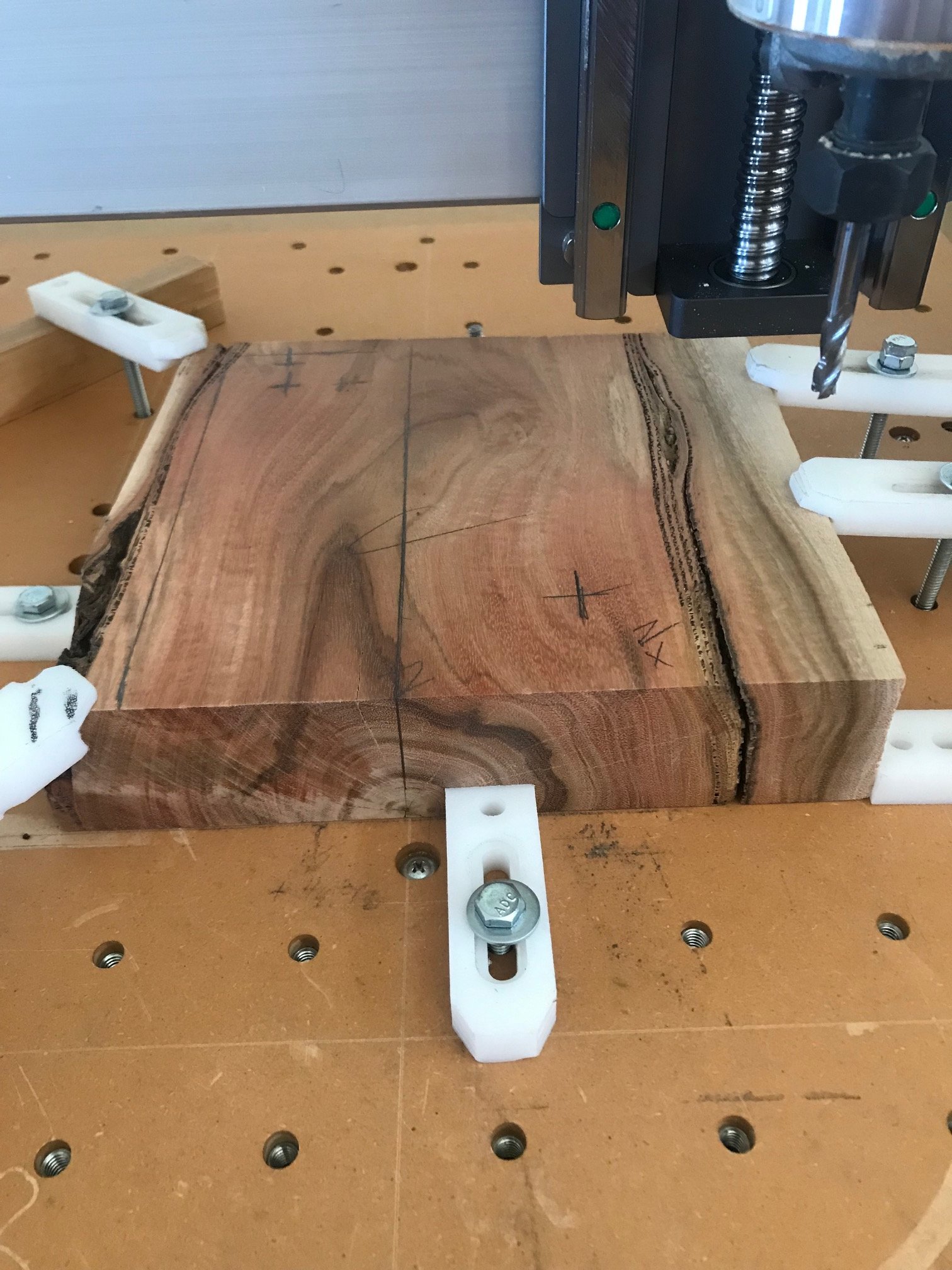
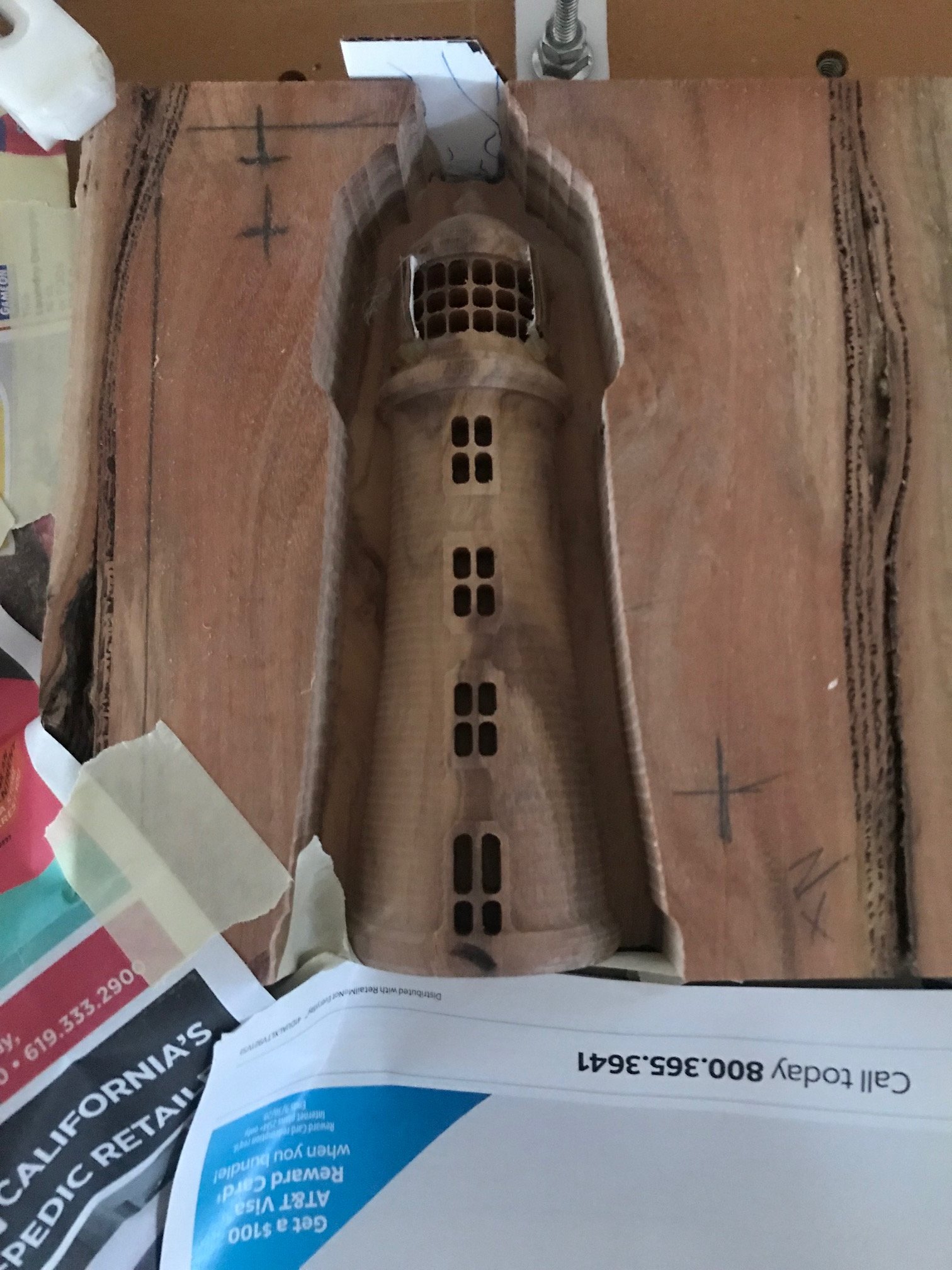
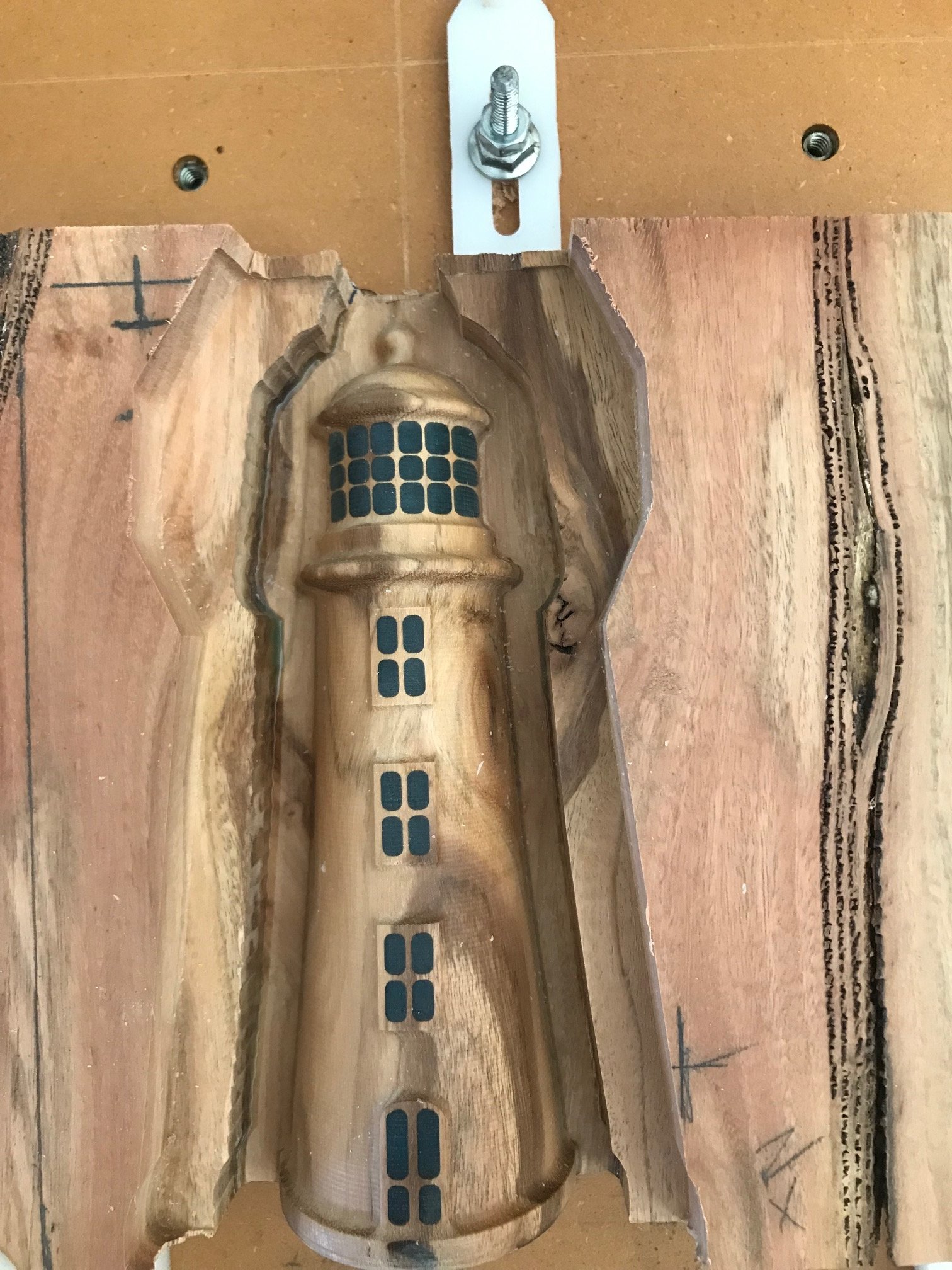
Here’s the block of wood (eucalyptus) ready for the first 3D roughing cut:
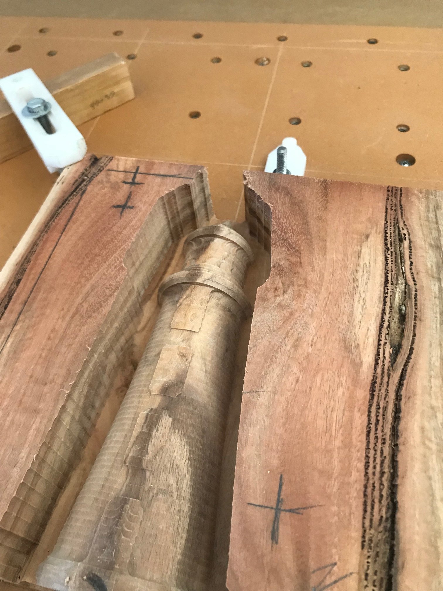
And after the 3D rough Cut using a 1/4" Carbide 3 flute end mill, 0.010 DOC, 40 IPM feed, 30 IPM plunge, and 12,000 router:
And the light cutouts using a 1/8" end mill. 0.030 DOC, 15 IPM feed 30 IPM plunge and 12,000 RPM router speed:
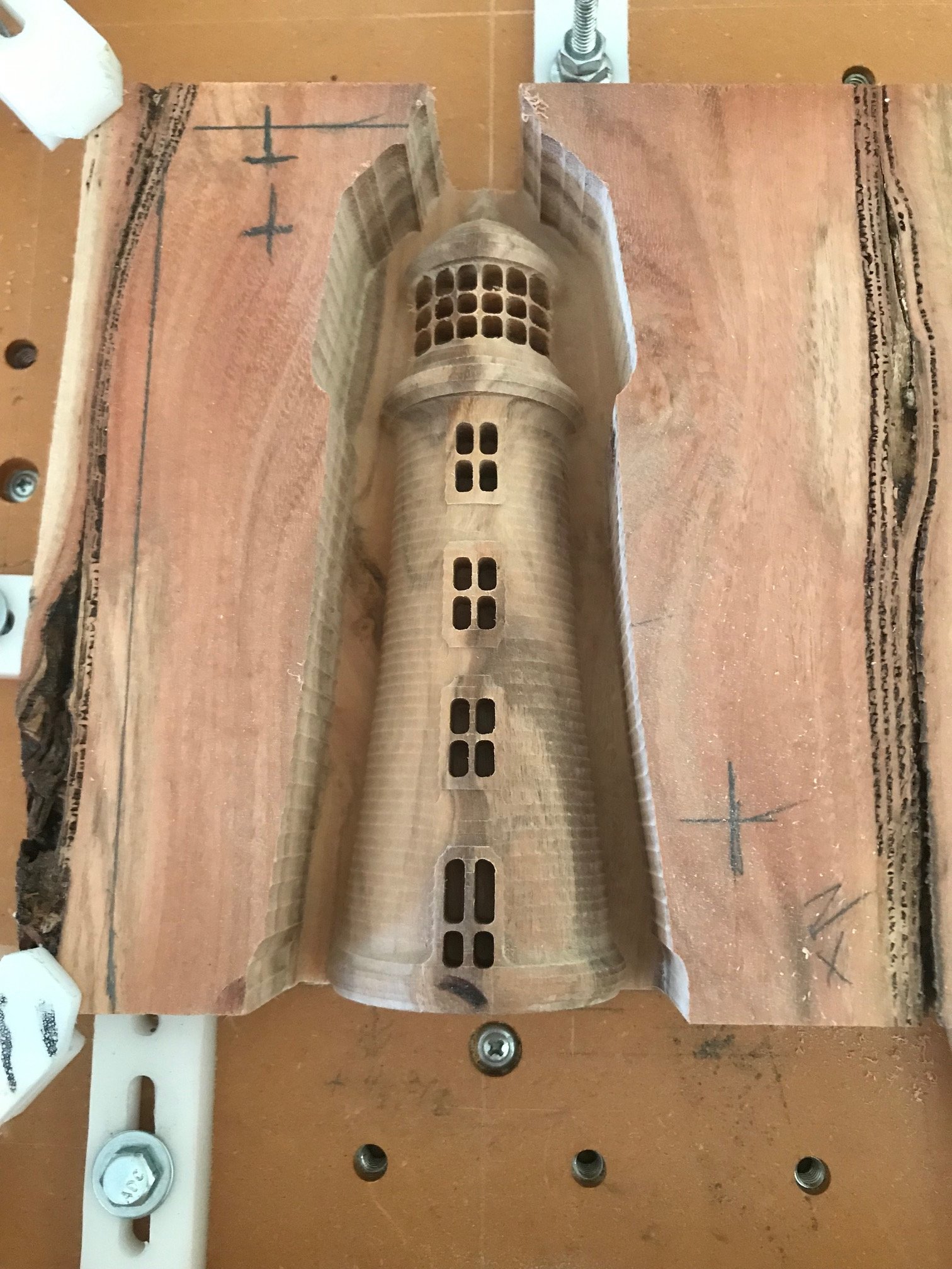
Ready for the epoxy fill. Had to build cofferdams on each side of the top windows to contain the epoxy. I DO NOT recommend pouring epoxy while on the spoil board, but I had finish cuts to make before flipping to machining the back side. If you do the same make sure you cover everything and block any paths the epoxy might follow.
I filled these with epoxy with a very little bit of metallic blue art paint:
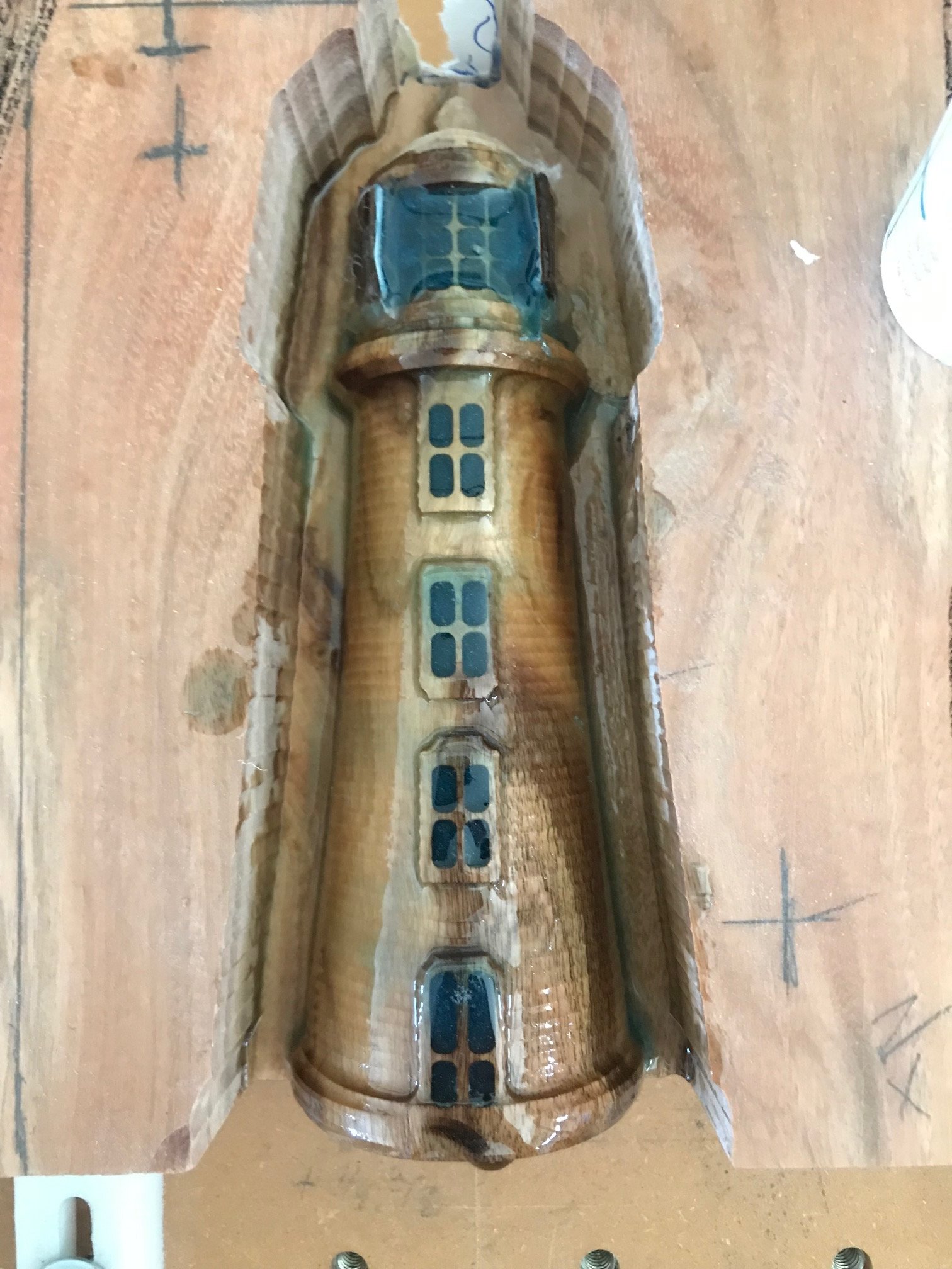
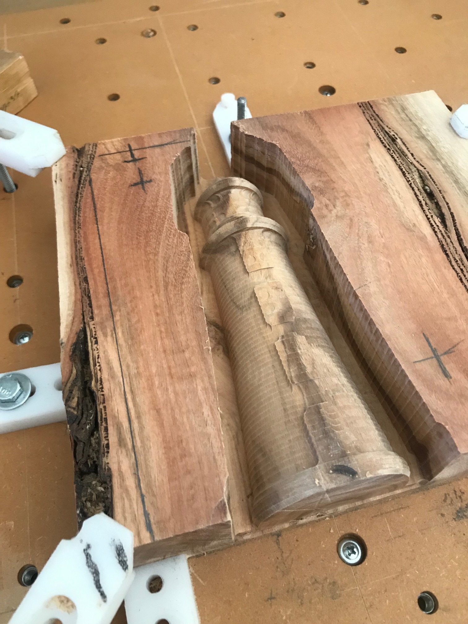
Here’s the first finish pass using a Carbide 3D 1/4" ball nose, 45 IPM feed, 30 IPM plunge, 10,000 router speed. I slowed it down some to prevent melting the epoxy. Aspire sets the depth of cut automatically, about .008 as it turns out.
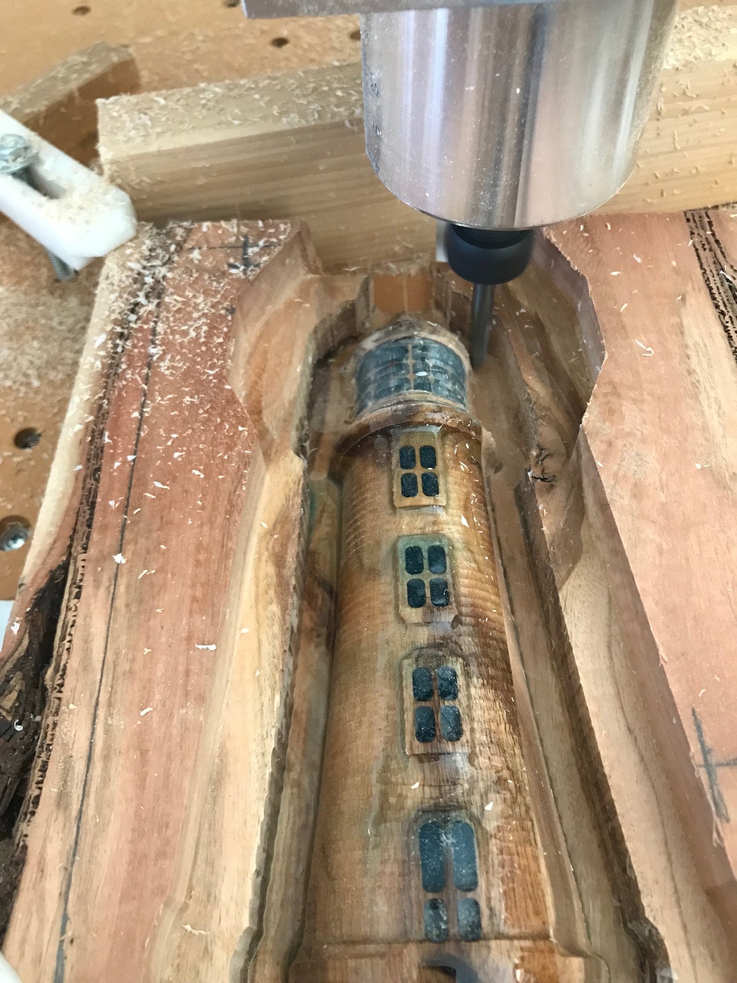
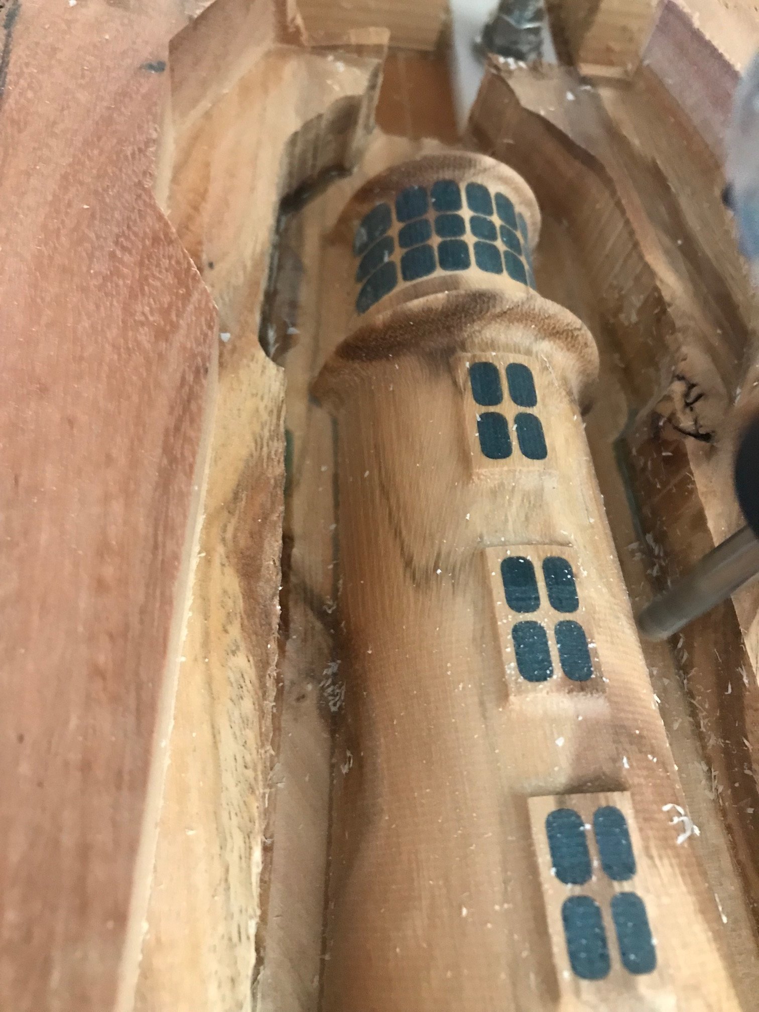
And after the second pass with the cutting direction 90 degrees to the first finish cut. This ended up being a very nice texture that I did not sand out.
I did make a profile cut on each side to make sure that the router collar wouldn’t hit the edges.
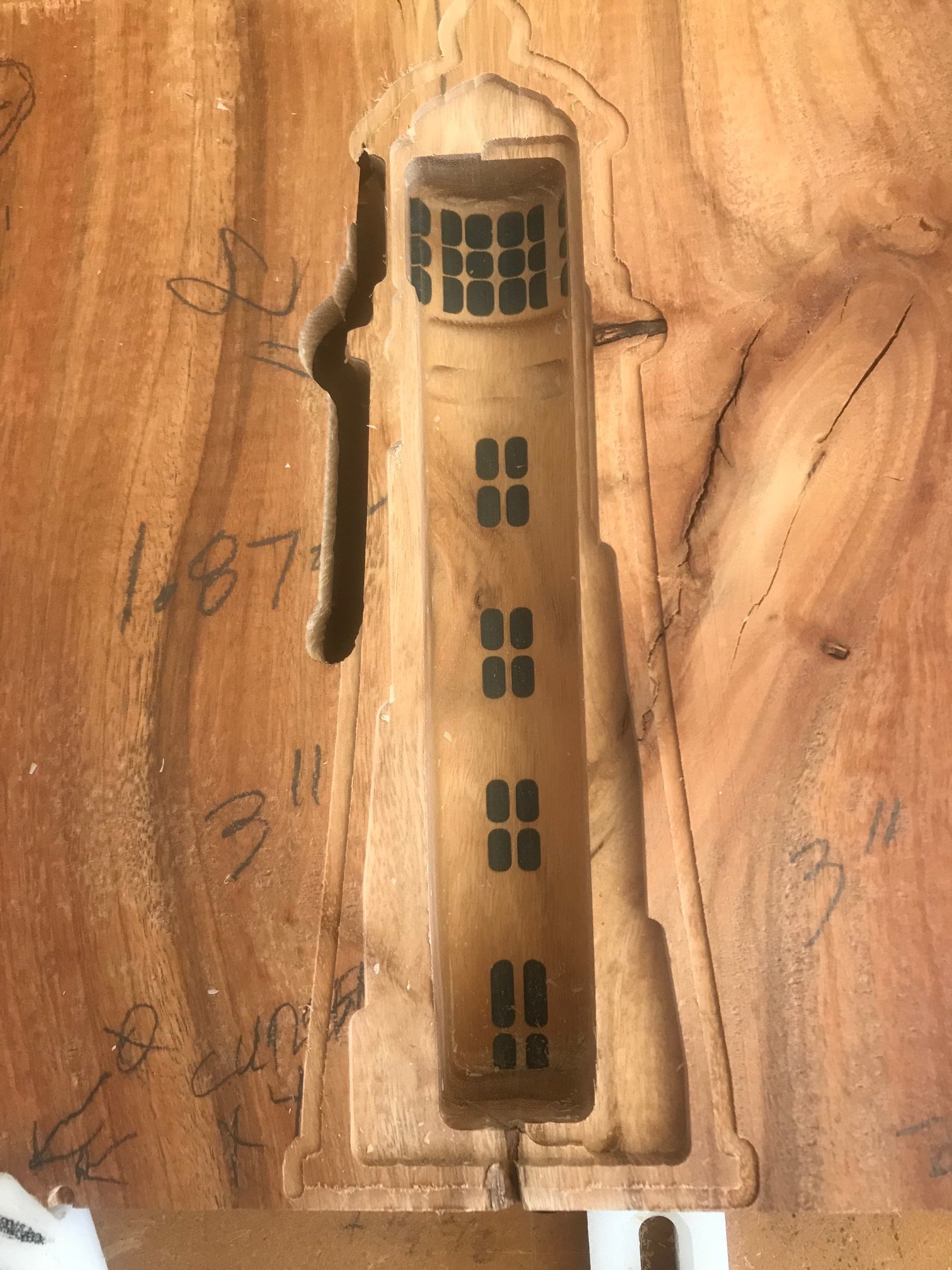
Forgot to take a picture of the flip jig holes which in this case were four 0.26 1" deep holes using a 1/8" end mill. I have aluminum bar that is 0.257 that have been cut to 7/8" and this fits in very tightly. Aspire has a nice feature, as I’m sure CC Pro and Fusion have, to copy these holes, flip to the backside in the project and paste them. Created a toolpath and cut matching holes into the spoilboard, flipped the stock and fastened it down and made the center cutouts and the initial profile cut to verify that the alignment was good with side one. Very pleased with the resulting thickness of the leftover stock after these cuts. I’m sure most of you will notice the profile cut that looks like it came all the way through from the side one. I forgot to check the bit tightness and it started going through the spoilboard. Hit stop in time that no harm was done, but make and follow your checklist, D’OH!:
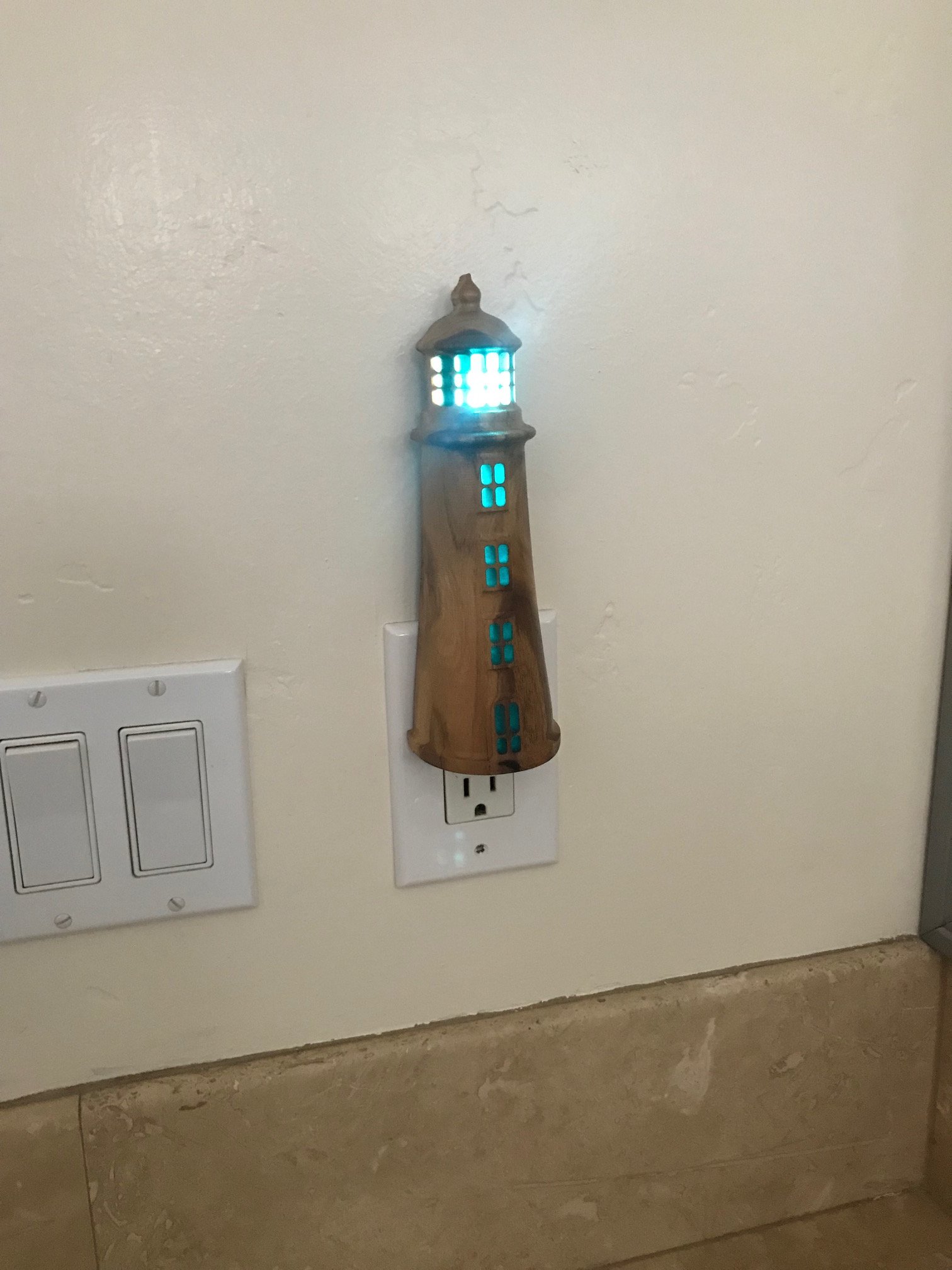
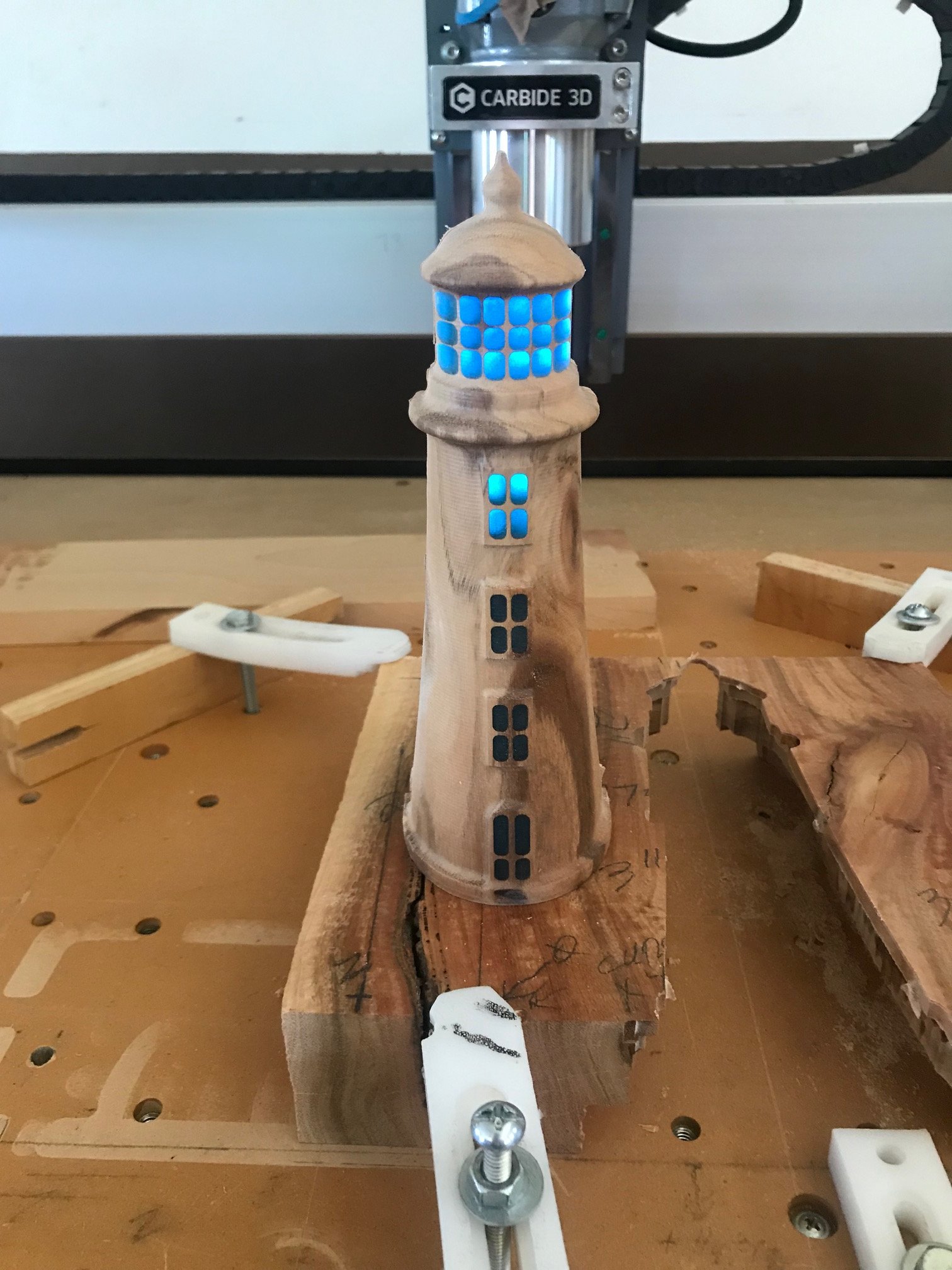
Here’s a look after the final cutout. Couldn’t help myself and put a flashlight behind to see how it might look, WOO-HOO!:
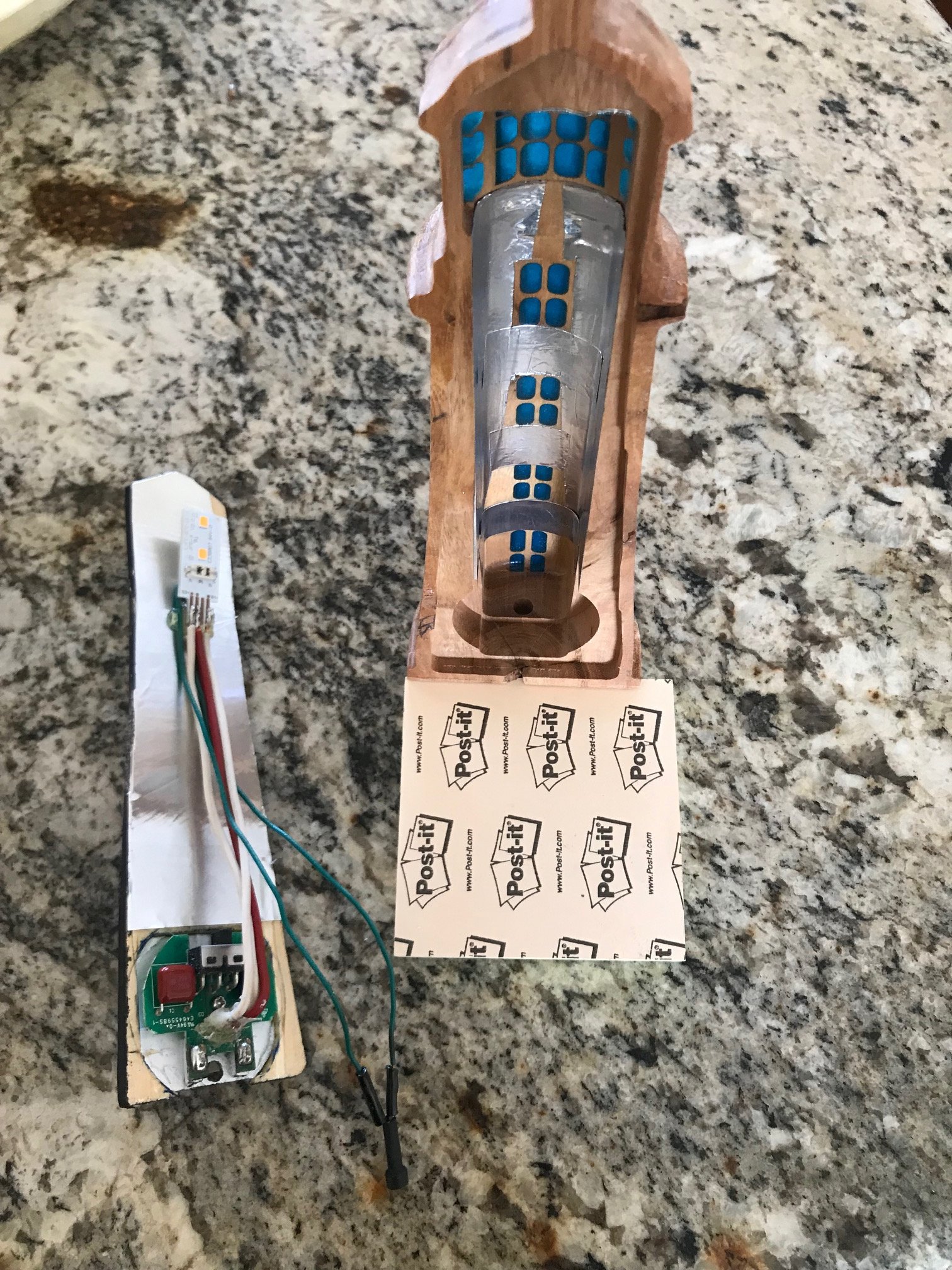
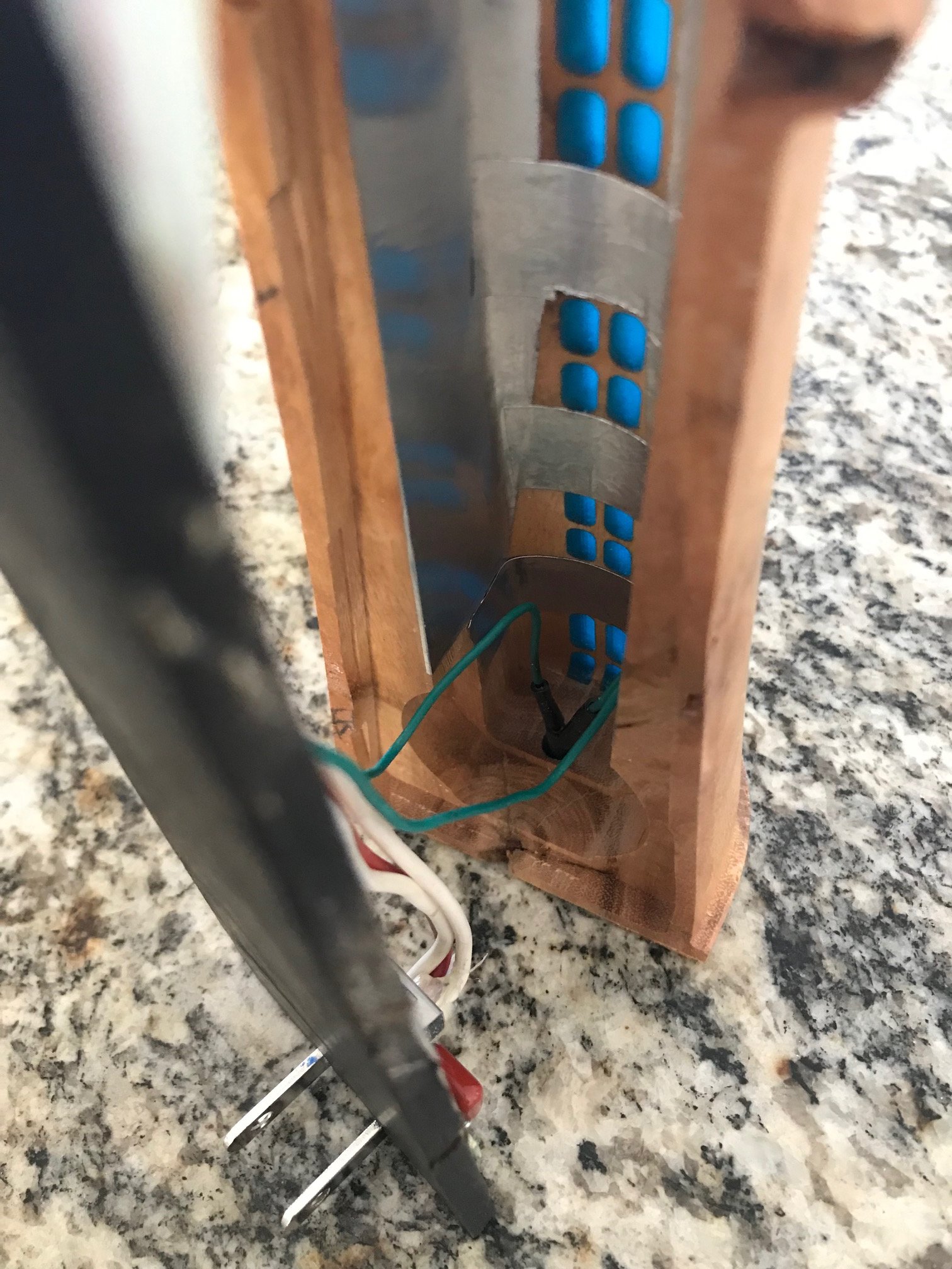
Here’s the modified nightlight guts and the back of the lighthouse. I applied metallic foil tape to the back and inside to reflect as much light as possible. The green wire are for the photocell which I drilled a hole for in the bottom:
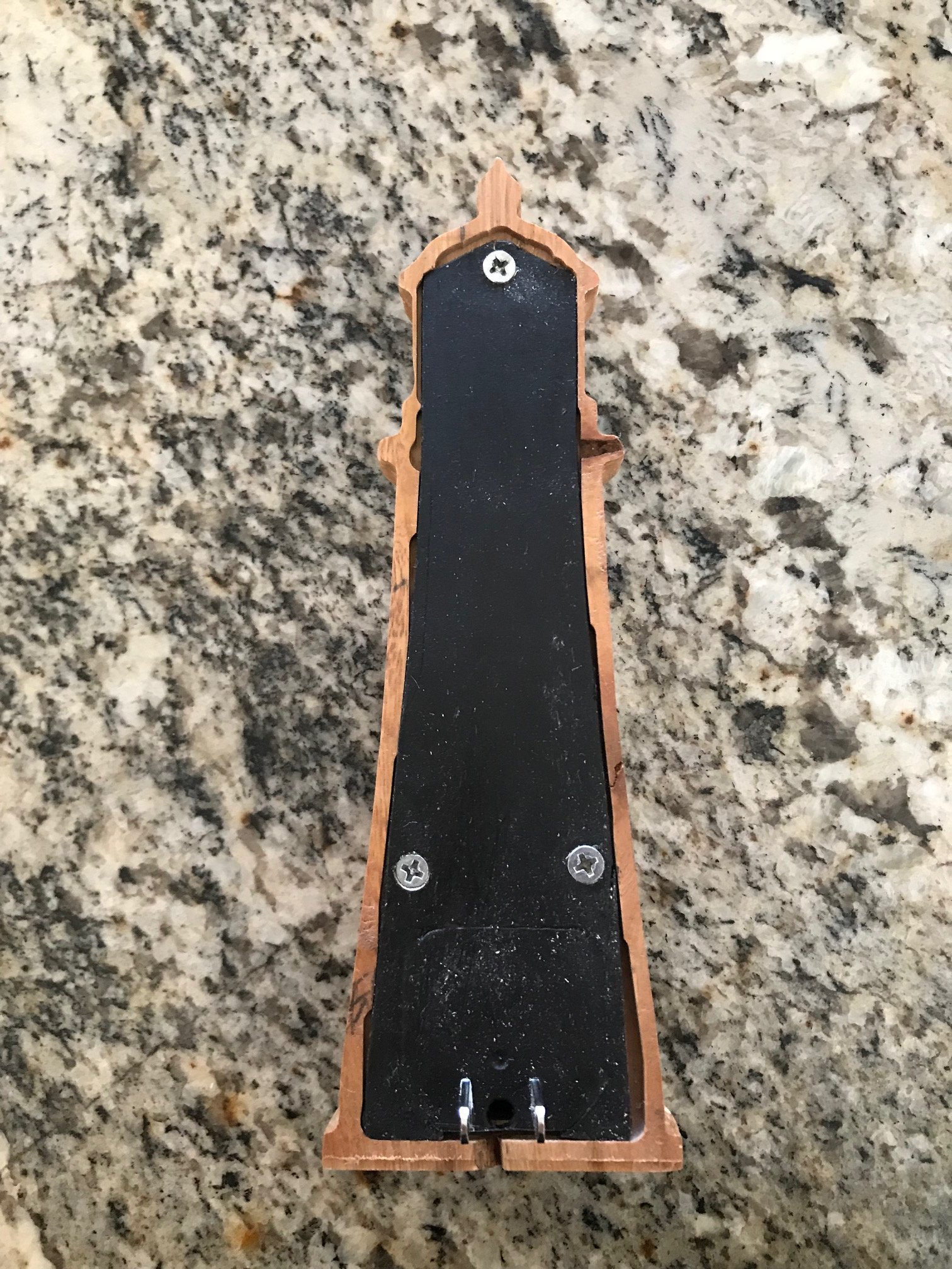
Here’s the final fitting before drilling screw holes to fasten the back on:
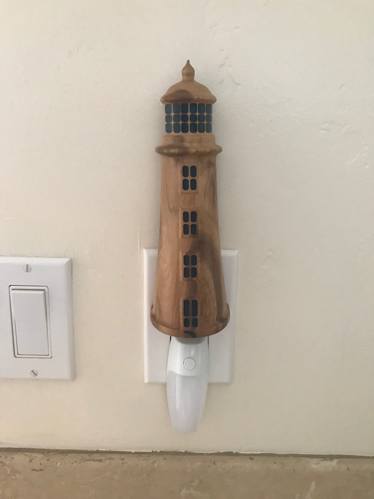
And here is the old and new nightlights together:
A couple of additional glamor shots now that it’s dark:
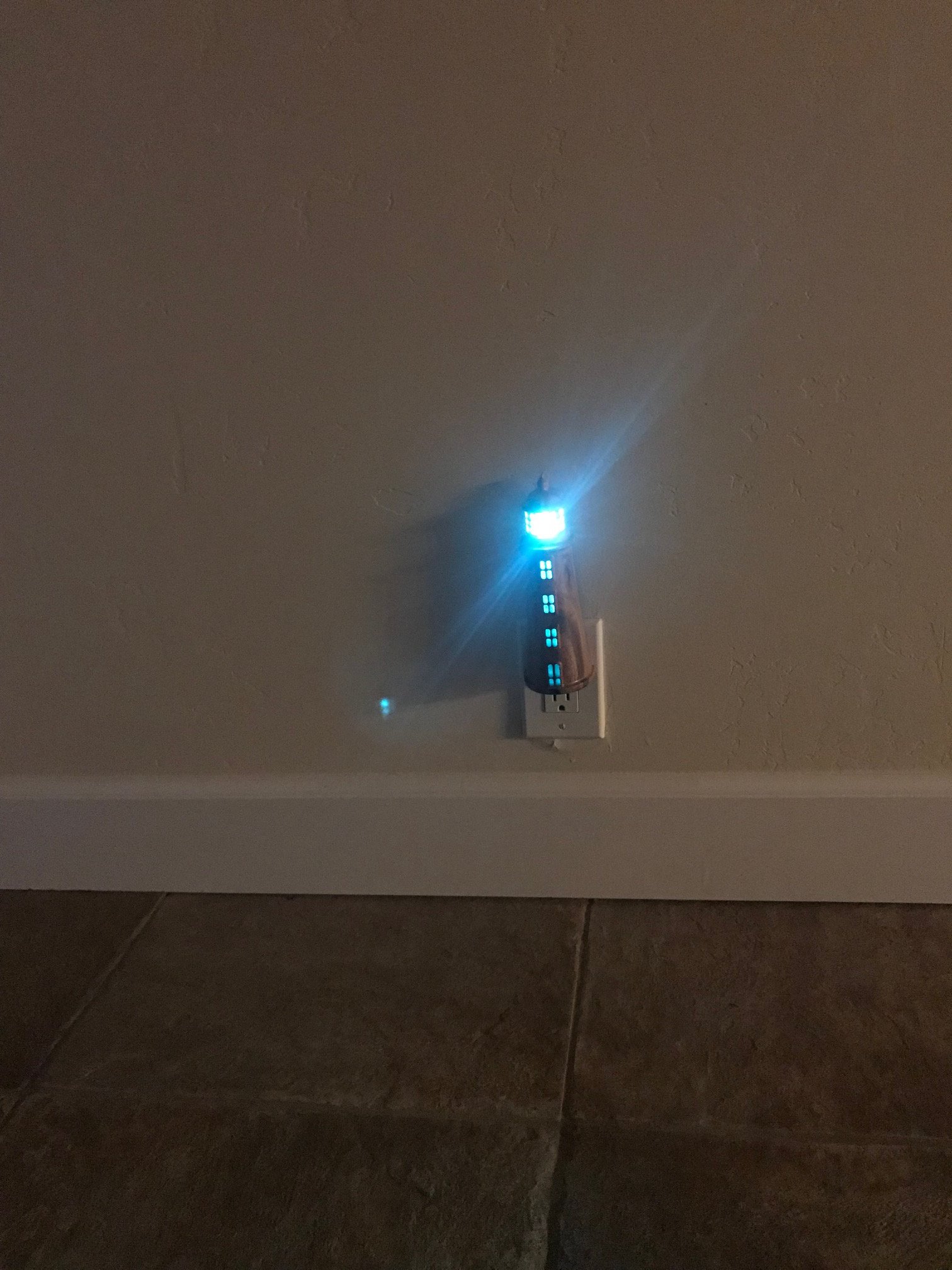
Looks crooked in that shot, but it’s not really.
And a close up:
Here’s the zipped Aspire file:
Per @Julien suggestion, here’s a link to the file on Google Drive:
https://drive.google.com/file/d/1MndJzRawiVrGNjp627dcwx01up1haY1a/view?usp=sharing
And the Cutrocket link:
https://cutrocket.com/p/5f71213802a11/
There are so many fantastic projects here this go around, thanks for organizing these contests @Julien and Carbide 3D for supporting them, what a great time!
EDIT:
I was able to save the lighthouse as an STL file, hopefully this will be helpful to those with CAD programs other than Aspire.
Lighthouse Nightlight.stl (2.1 MB)
20 Likes
Great finish (it’s becoming a thing!), it’s now time for voting.
7 Likes
Incredible result. That wood is freaking gorgeous and goes so well with the epoxy. The lighthouse is also so fitting for the purpose!
Had to chuckle at your reference to “the checklist” when the bit slipped. I’ve had moments like that where I’m just so perplexed as to how I could forget something like that, but in the hurry and excitement to get rocking, I hand tightened the bit, got right to zeroing or hold down work, final file changes… then ready, set, fail! Glad it wasn’t catastrophic and amazing result!
5 Likes
Greetings John,
Thank you! I have to admit though, it’s a humbling experience being among what I consider the giants of design and execution on this forum!
Your “ready, set, fail!” comment has given me another idea to pursue, thank you for that as well!
5 Likes
I second that! I’ve not done one of these contests before and only followed a few here and there. My project was quite small compared to the beast mode output of others (way bigger pieces of wood, more operations, bigger assemblies, more design). Really amazing to see what was cranked out in ~3 weeks of free time 
4 Likes
Great job to everyone who submitted! I hope I make time to get in on the next one.
@Sherpa, did your minions quit on you?
4 Likes
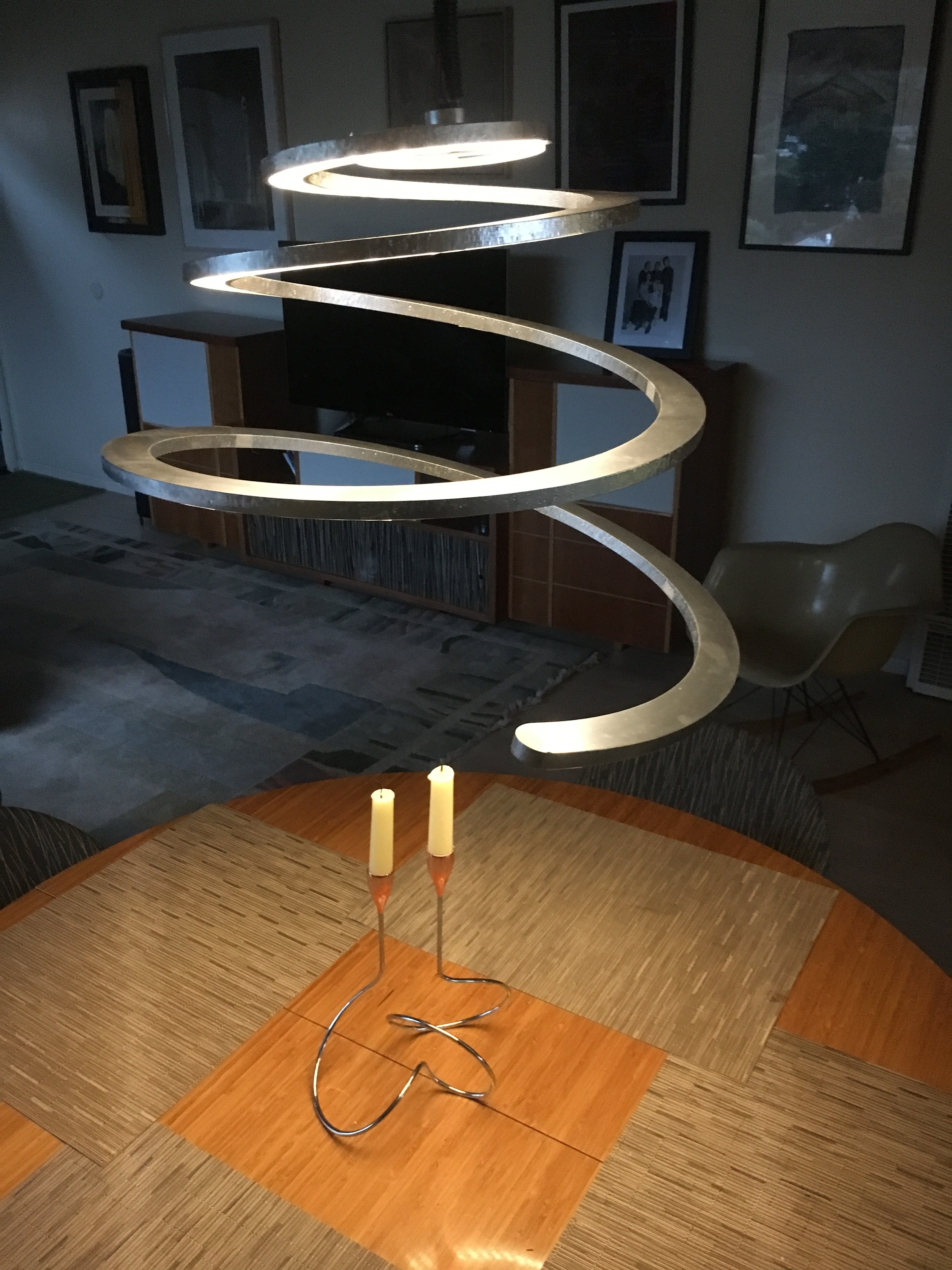
This is not intended as an entry , just a project of interest to the Challenge topic. I did this lamp about 3 years ago on a Shopbot. I liked the rough finish on the edge and painted it in aluminum as that was the original material envisioned for this. The lamp consists of the main spiral in 1/2" plex and a 1/16" lens in diffused plex set flush into the channel. . The fit went really well after the first cuts. That rarely happens w my projects. The cool feature is the motion activation sensor which not only turns on the light but if you leave your hand in place it dims the light, until you remove your hand. A quick swipe turns off the light as well. ![SPiral lamp1|375x500]
(upload://rNoL5d0OybZKmxfnOIVxDpaUJ0Y.jpeg) SPiral12.9 3chanAI.pdf (292.5 KB)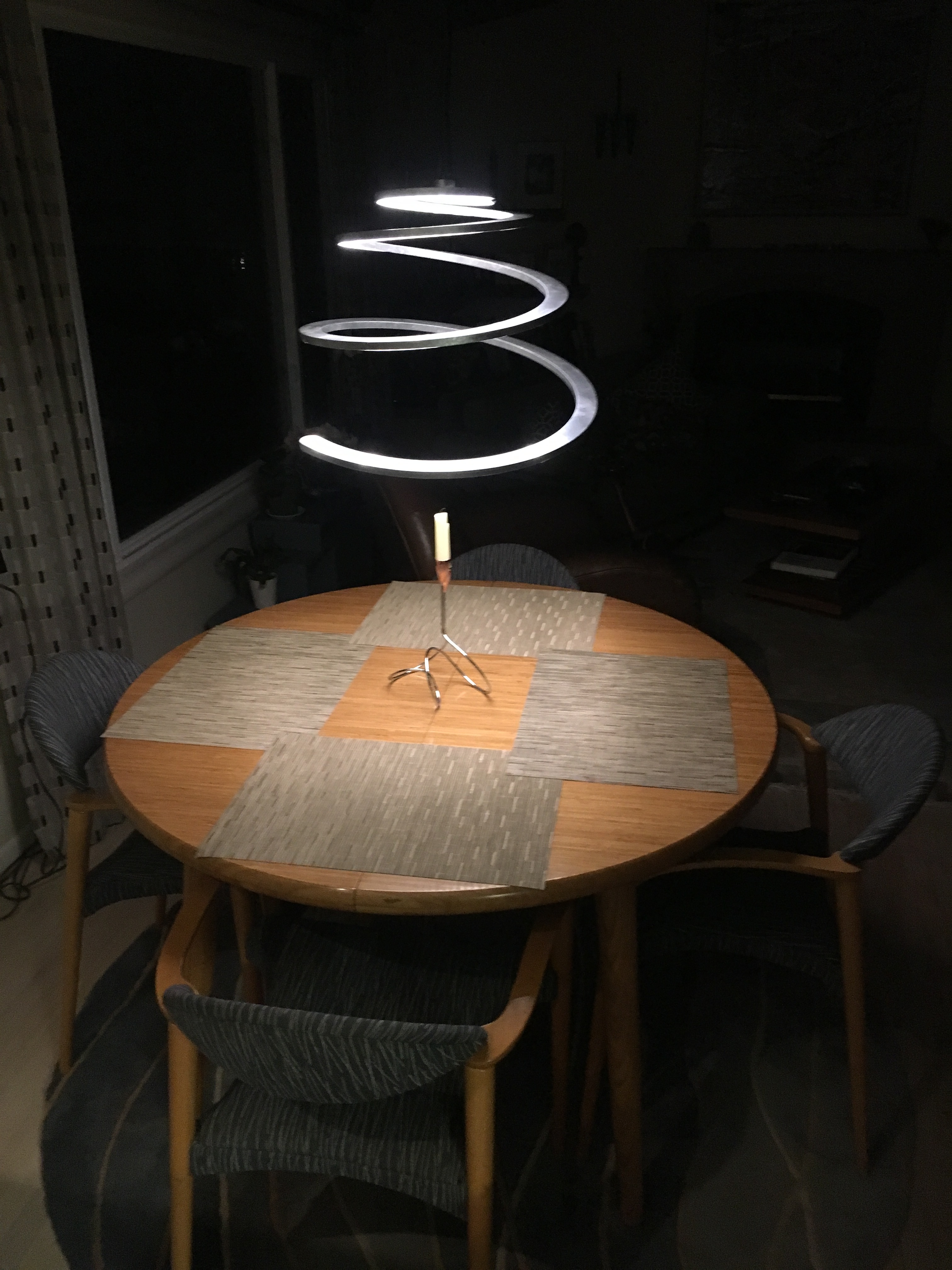
9 Likes
This is really cool Aaron. Do you have another page with additional details about the lamp build?
@jwhendy Your suggestion to reuse the locating pins as described on Imgur is certainly worthy of mentioning on these boards. That’s a shortcut I’ll definitely use in the future!
No I dont, I posted the pdf , you can plan tool paths from that. One key item is the kerfed LED strip that allows bending along a curve, most strips only allow wrapping. The other was the sensor switch, it’s embedded in the part where it connects to the wire. This site would not let me upload the video I have, but here it is. [https://youtu.be/oJaZCm962SA]
2 Likes
Thanks for the suggestion and kind words. I made a post explaining the method!
2 Likes