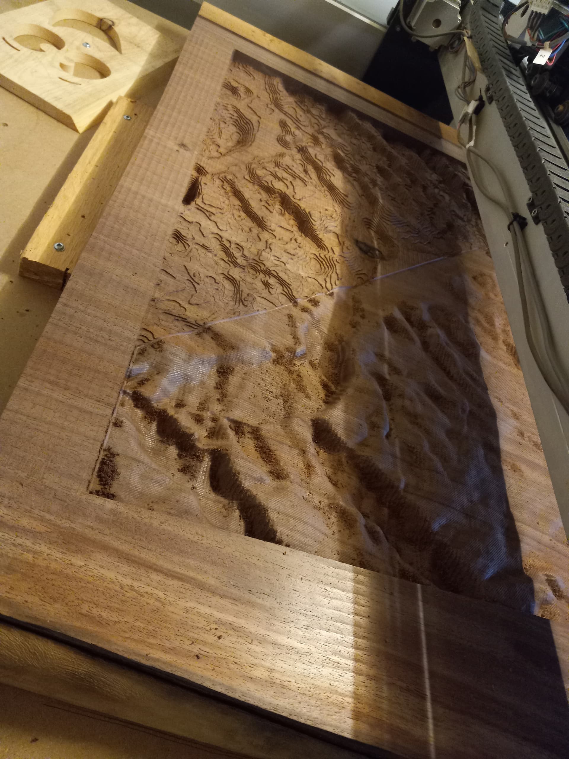
During cure times I worked on machining the Lake topo in the other slab. Kind of the same process, except this time I was better armed with some lessons learned. Got a great tip from Tod1d which came from Will some point earlier about visualizing depth of topo features during carving. Link to that thread below. I think that is extremely helpful! So thanks guys!
This topo I had to use a different site for the topo… Really awesome site I found somewhere on here. Here it is again for those who haven’t seen it!
https://touchterrain.geol.iastate.edu/
One of the other struggles I learned from was in long machining times associated. The Canyon was nearly 25 hours (almost 40 total) of nearly continuous machine time. Lots of pausing and doing other things around the shop. Not great on my steppers. Had another thread on here where I learned about the toolpath tiling feature, and also realized I was out of date on my version of Carbide Create.
Deep topo map question - CNC Machines / Shapeoko - Carbide 3D Community Site
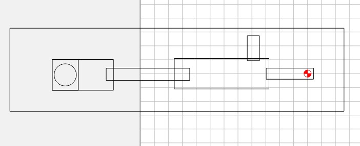
Even though I didn’t use tiling, I did figure out I can use geometry and do roughing (and probably could have done finishing) in smaller blocks where I could actually shut the machine down. That was extremely helpful, and the way the machine and software seamlessly blended the roughing across those blocks was impressive. Again, Thank you Will for that assistance.
One thing I am totally unhappy with and learned from was that in order to bring this small little mountain lake to a size where it showed up, I had to zoom way in. And the difference in scale between 50 plus miles of topo in the canyon and what is probably less than 2 miles for the lake, it was just a different look. Customer loves it, so works for me. Scale is an issue. If making matching pieces, I highly recommend you keep the scale of the topography as close to the same as possible.
Lighting the lake was different than the canyon of course. I ended up using a trick I got somewhere here a long time ago. Put a piece of trace paper on the flat spot created by the lake on the actual slab while it was on the machine, retaining the original zero. Once traced, I put two marks on the paper exactly 1 inch apart. Scanned it, brought it over to carbide create, and scaled using the 1 inch marks to size the lake outline. Rotated and placed it in the original cut file, based on that X/Y zero, and then set a new Z to the height of that flat spot. Ran air once to make sure it was going to cut right where I wanted, and then recessed the lake for epoxy. Inside of that, I offset and cut a deeper recess for a piece of plexiglass which I sanded to help diffuse light, and then a deeper still pocket to hold the fiber. Cut the plexiglass using the same outline, offset inside by .008 so it would fit. Got the lights in, plexiglass in and covered in epoxy. Didn’t get much for pictures during that process. Also embedded a small laser engraved puck in maple marking the exact location he proposed to her. Had to flip it over, and also get a recess machined for the light source, etc. It oriented 90 degrees the other direction from the canyon, to avoid deep topography features. Easy enough to accomplish in CC. Again, zero was the penetration.
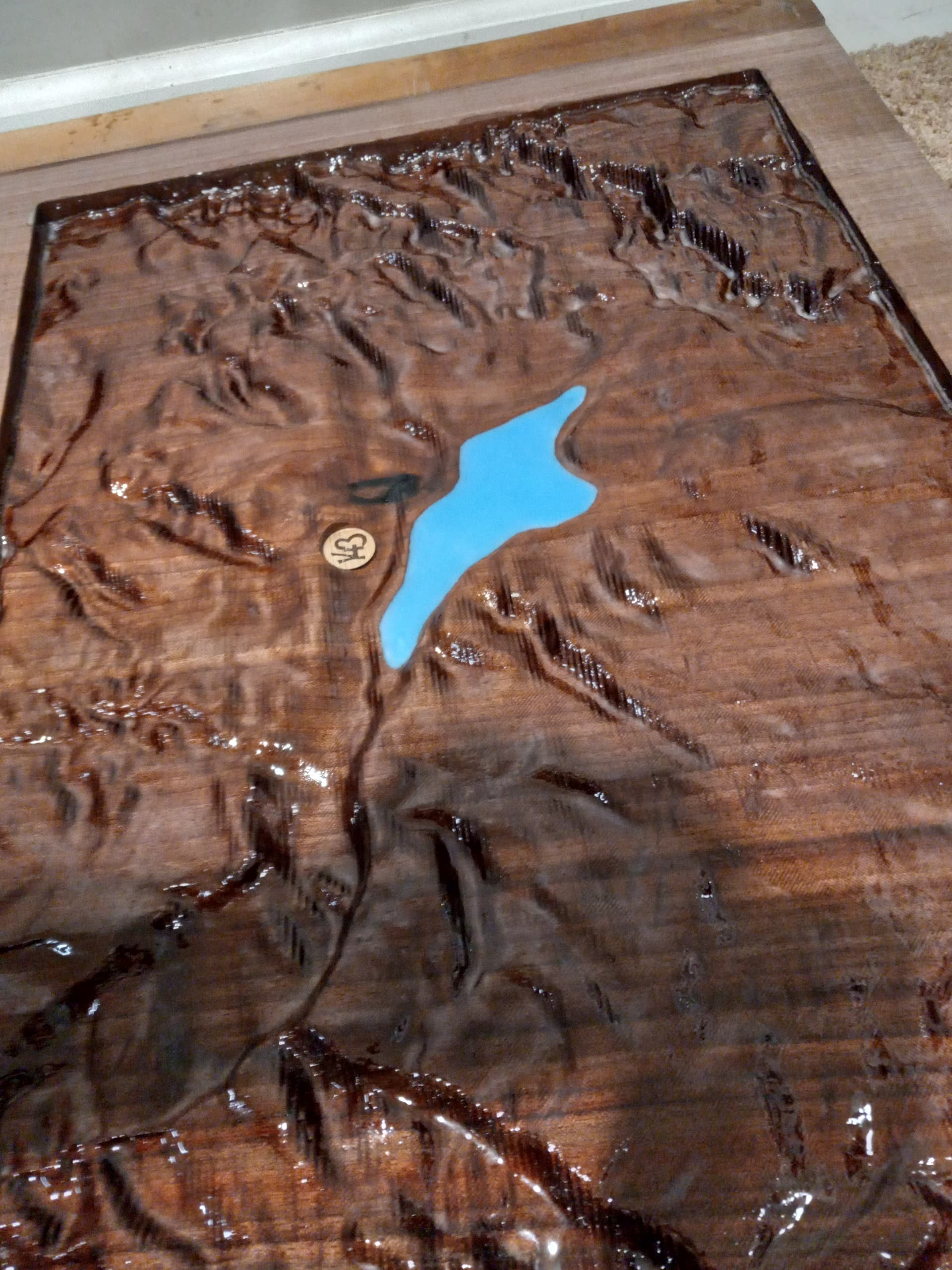
After a seal coat of epoxy, I got this one poured in deep pour yesterday, and that is where we currently sit.
