Community challenge #8: 3D object from 2D layers (closed)

Hi,

Thank you all again for the entries in challenge #7, it was fun to see what you came up with!
This time around, let’s pretend our Shapeokos and Nomads are laser cutters for a minute.

Challenge #8 is: “Make a 3D object from 2D layers/slices/pieces

Here are a few random examples I grabbed on Pinterest, to give you an idea of the theme:
example2
example1.PNG
example4
(and then there are the gazillion 3D animal puzzles)

The rules for this eighth challenge are:

  • submit your entry in this thread:
    • the final object must be assembled from individual 2D cutout pieces
    • the pieces must be cut (with endmills) on a Shapeoko or Nomad (no laser! no waterjet, no plasma torch, plain old endmills!)
    • you must include pics of the finished piece.
    • you must include the design file (so watch out for any licensed vectors you might use, that might not be shareable)
    • tell us about your mistakes, tips and tricks, etc…
  • you can post multiple entries if you want.
  • timeline:
    • deadline is set to May 27th, midnight PST
    • there will then be 7 days for voting.
      • voting will be open to legit community members only, and the jury reserves the right to remove votes from “outsiders”, and will also break any tie.

We have some pretty “wild” prizes this month:

  • First place : 4 Tiger Claws + 2 stainless steel Gator Tooth clamps:

  • Second place : 2 Tiger Claws + 2 aluminum Gator Tooth clamps:

  • Jury’s prize : 2 aluminum Gator Tooth clamps:

image

And as usual some cool Carbide3D swag!

image

Good luck!

13 Likes

One software tool which will help in such designs is:

http://flatfab.com/

(to help out the folks who aren’t cool enough to use Autodesk Fusion 360)

7 Likes

-The look on my face as I glance at my 670 hole 5/16-18 threaded Spoilboard…

*Contemplates ordering 670 1/4" Heli-coils…

3 Likes

Will, have you used FlatFab to cut on the Shapeoko? Their videos seem to only show laser cutters and objects.

FlatFab gives me the impression that they are dormant.

No, I just collect stuff such as that and note it in the wiki in case I ever need it or someone asks after it.

If I were submitting something for this it would probably be my current Coopered box/pirate chest design:

2D into 3D hmmmm :thinking:

How much “post processing” is allowed?

2 Likes

Post processing as in G-code generation or as in manual operations after the cut is done / the piece assembled ?
Anyway, as long as you feel you meet the rules (cutting 2D pieces and assembling them to make something 3D), post-process all you want!

1 Like

makes me wonder about an stl2svg tool :wink:

5 Likes

Well that would be certainly be quite useful for the community and this contest :slight_smile: (hint hint)

1 Like

For anyone that hasn’t tried it, I have had very good success with Slicer for Fusion360

It makes those crazy awesome sculptures quite simple

4 Likes

So 2d only or can we use something like slicer on a 3d model… would still yield sheets being cut and assembled but some parts could possibly have 3d machining on them as well…

That’s fine, and I expect several entries to be based on the Fusion360 slicer (I may have one of those in the works myself :slight_smile: )

1 Like

RC Sport Plane

I am not sure if this project qualifies for this contest. The design work was performed Nov-Jan, parts were cut in Jan – Feb and assembly happened in Feb and March. If not, I can delete this and just move it to the project gallery. Let me know.

Here’s my method of using the Shapeoko to cut 2D parts to create a 3D RC plane! This is a project that has been in the works since last November when I bought an XL machine. This is the second plane I have designed but the first one where I cut out the parts on the Shapeoko.

Designing:
I first decided on the basic parameters. For this build I wanted to create a good all-around sport plane to fly at my local RC field with others. I wanted a mid-sized plane that is easy to cart around and store. And electric powered like all of my planes and able to use batteries and other components that I already have. I wanted to use 3/32 and ¼ in balsa and 1/16 in plywood for the main construction materials. Based on other existing designs and knowledge, this lead me to a plane with a 55-60 in wingspan and a target weight of 4 to 5 pounds.

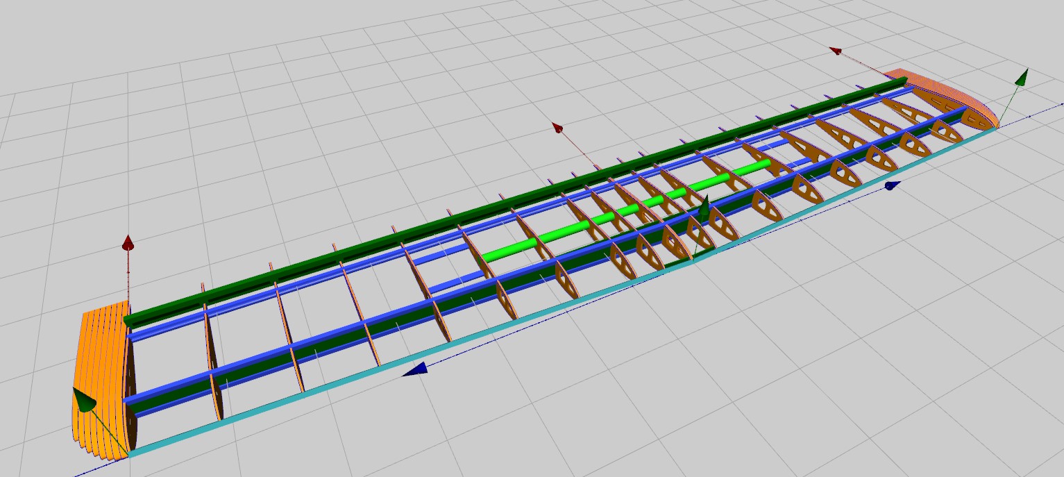
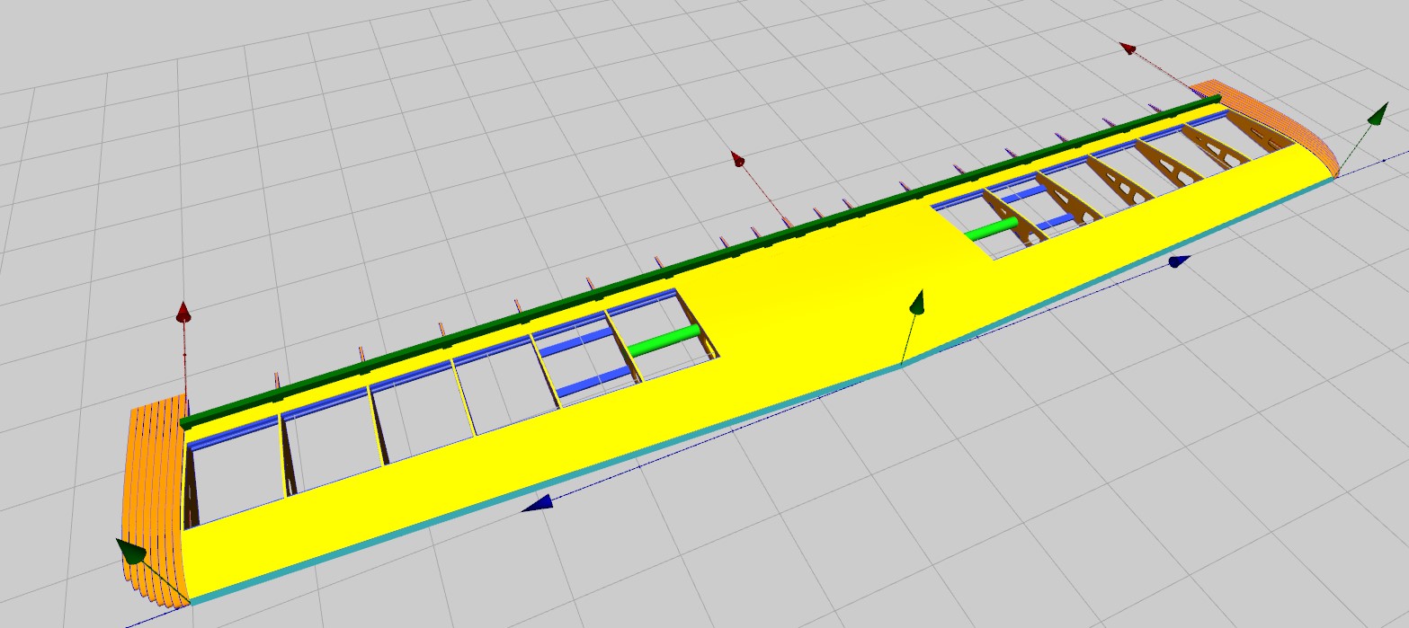
I used 3 different programs to help with the designing. WingHelper (https://www.winghelper.com/default/) , devFus and devCad CAM-Pro (http://www.devcad.com/eng/default.asp) I started in WingHelper to create the wing. This program basically allows you to specify and visualize a wing on the computer and will generate the needed parts in a DXF file. You can specify almost any airfoil and many different wing configurations. I settled on a 59 in span with an overall wing area of 577 sq-in.

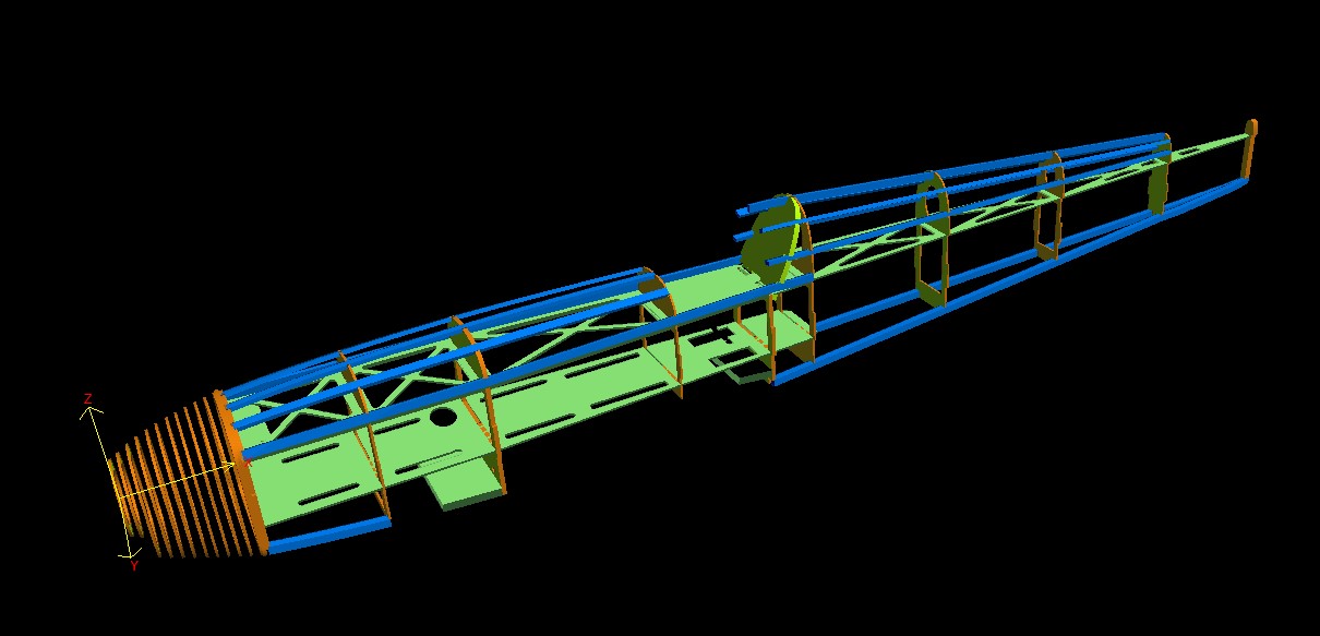
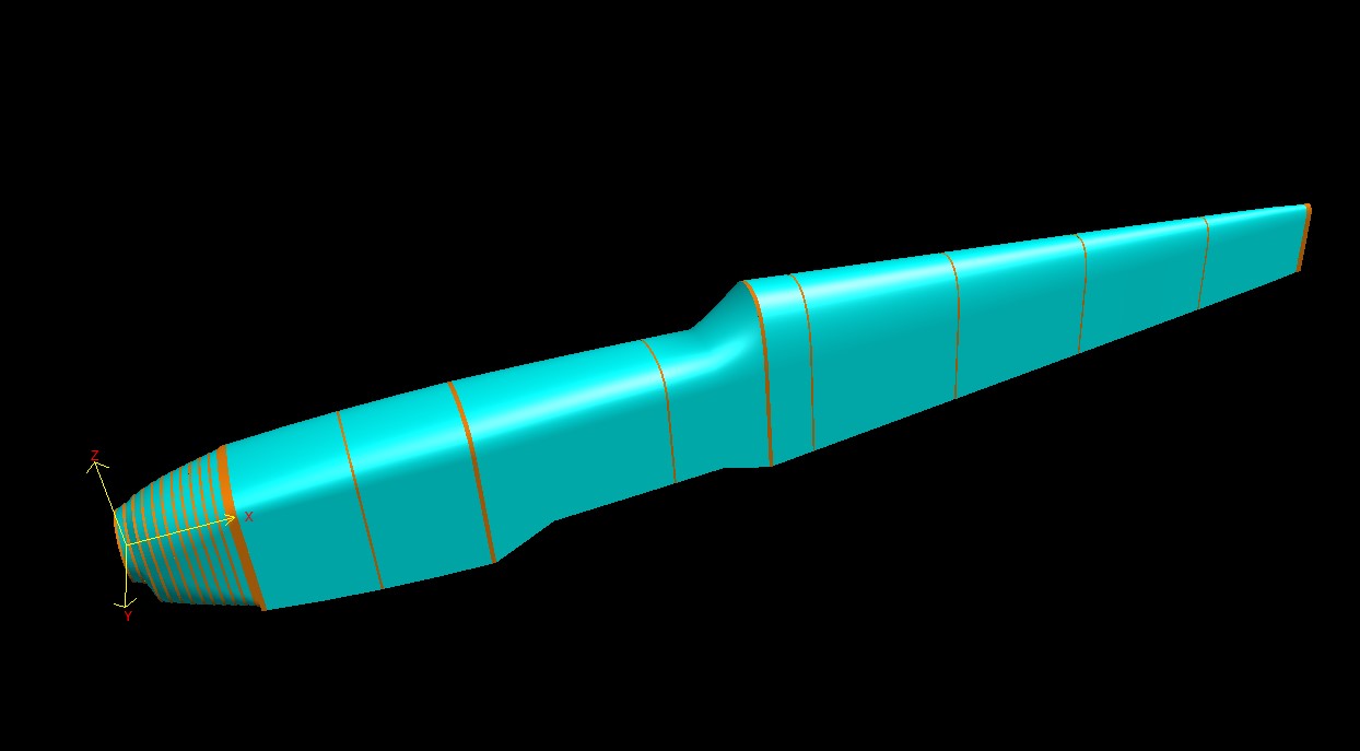
I used devFus for the basic fuselage design. Overall length and width determined by fitting in existing components and basic RC plane design theory for my chosen plane type. (There are many good books…) Like WingHelper, you specify many parameters and can “see” the design on the computer in 3D. I then outputted the needed 2D parts in DXF format.

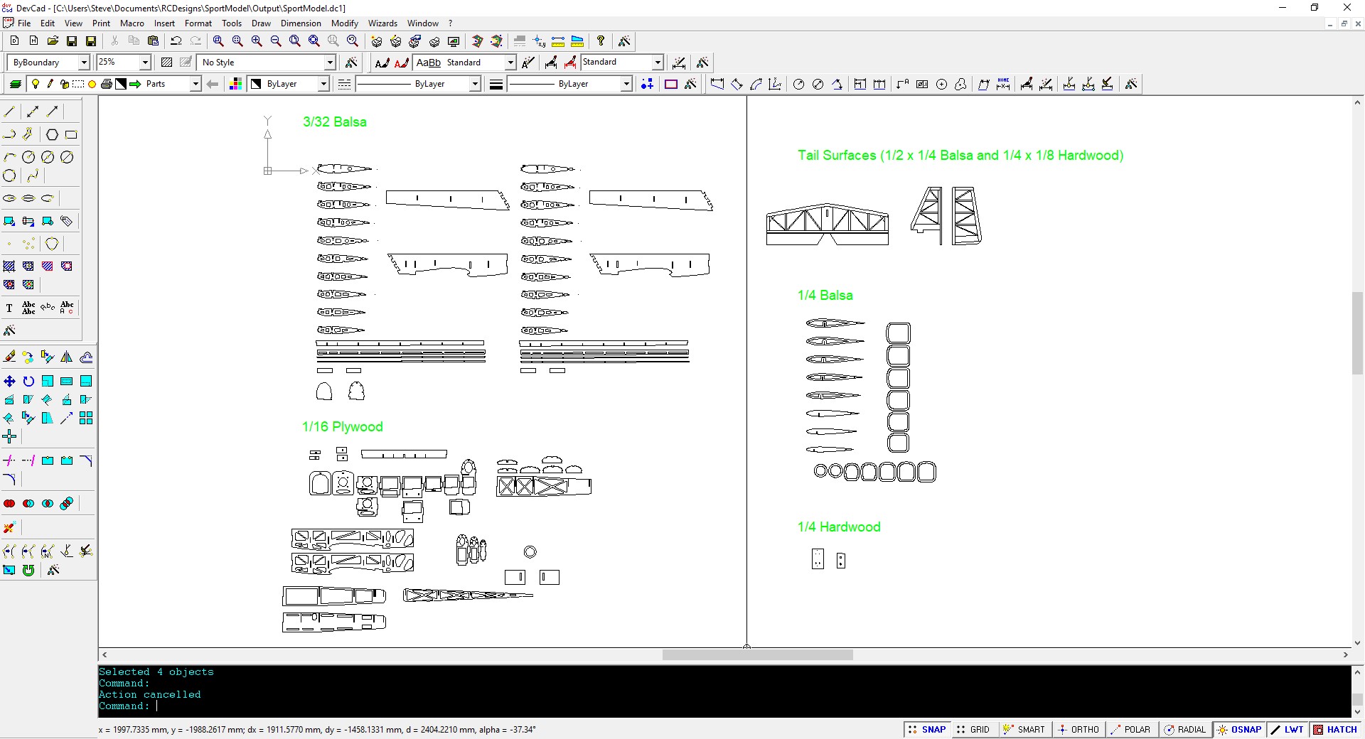
Final designing was done in devCad. It’s a general purpose 2D cad program. I fixed and change things that I was unable to do parametrically before. I also created the stabilizer and rudder.


SportModel.dxf (1.5 MB)

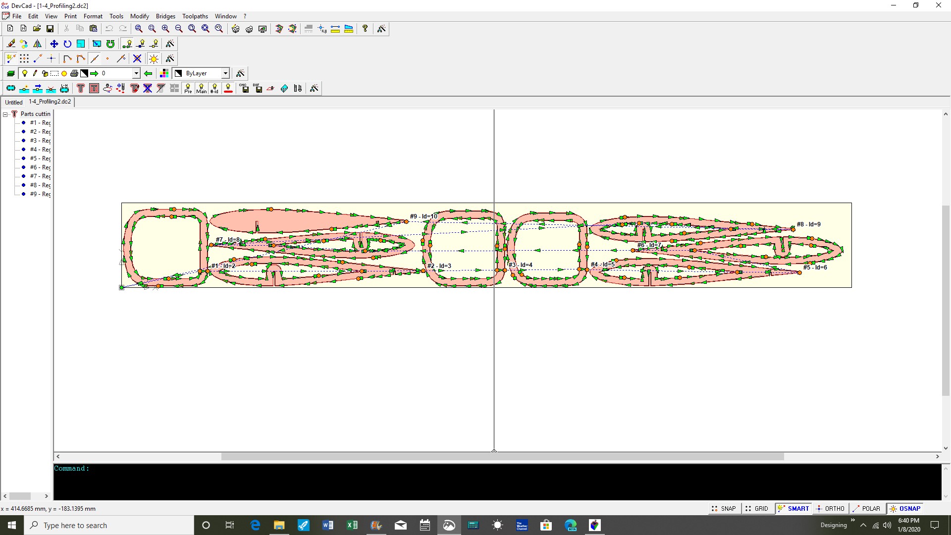
I also used devCad to do the CAM work. It has wizards to help with parts layout and creating the tool paths. They work quite well and you can change anything that isn’t exactly that you want. I did not use the auto generated tab feature because they were too often placed in a poor place. It was quicker to assign them individually. devCad supports a number of gcode post processors. There is not one specific for the Shapeoko, but the generic GRBL one works fine with Carbide Motion and the Shapeoko.
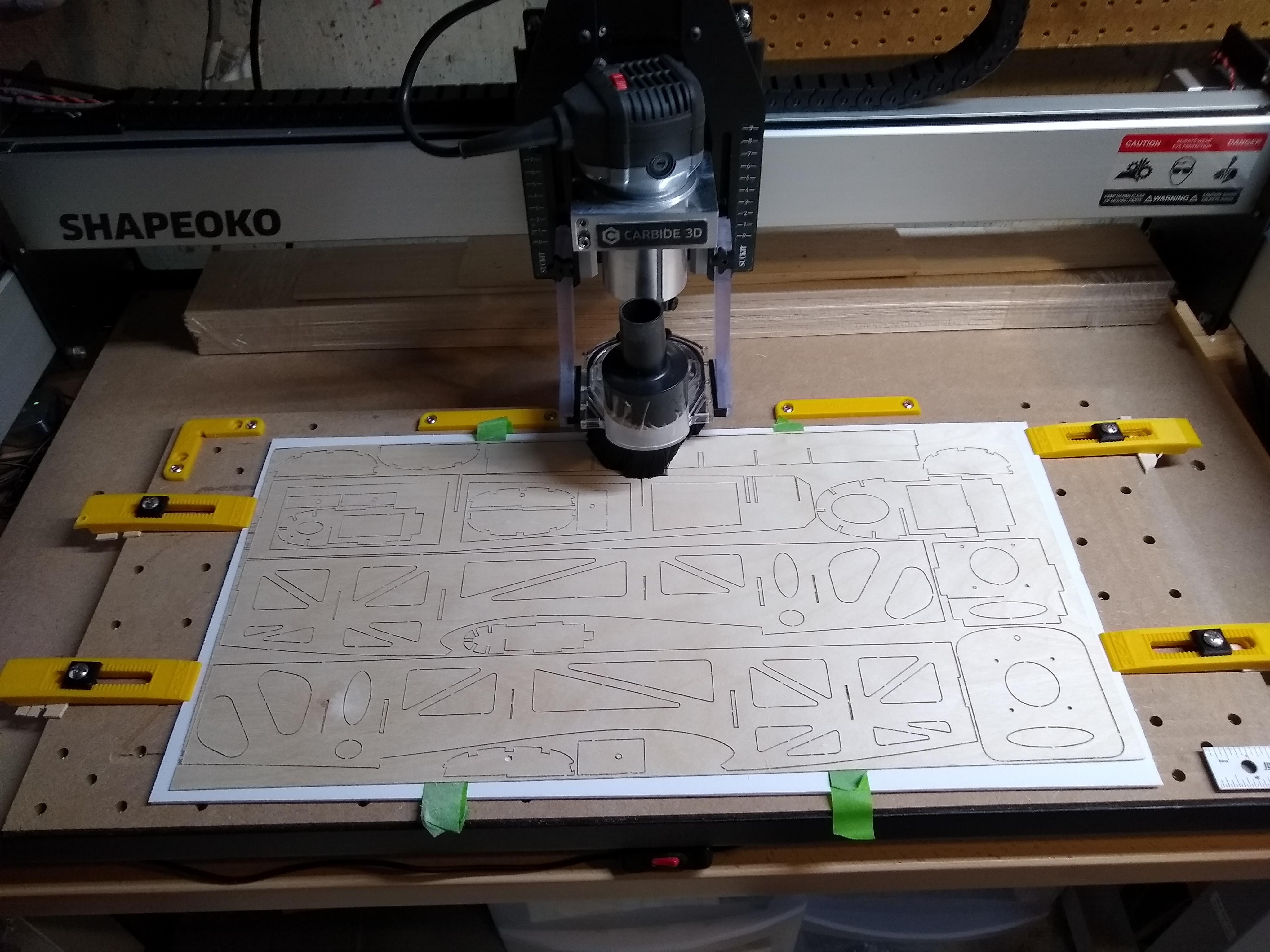
Cutting:
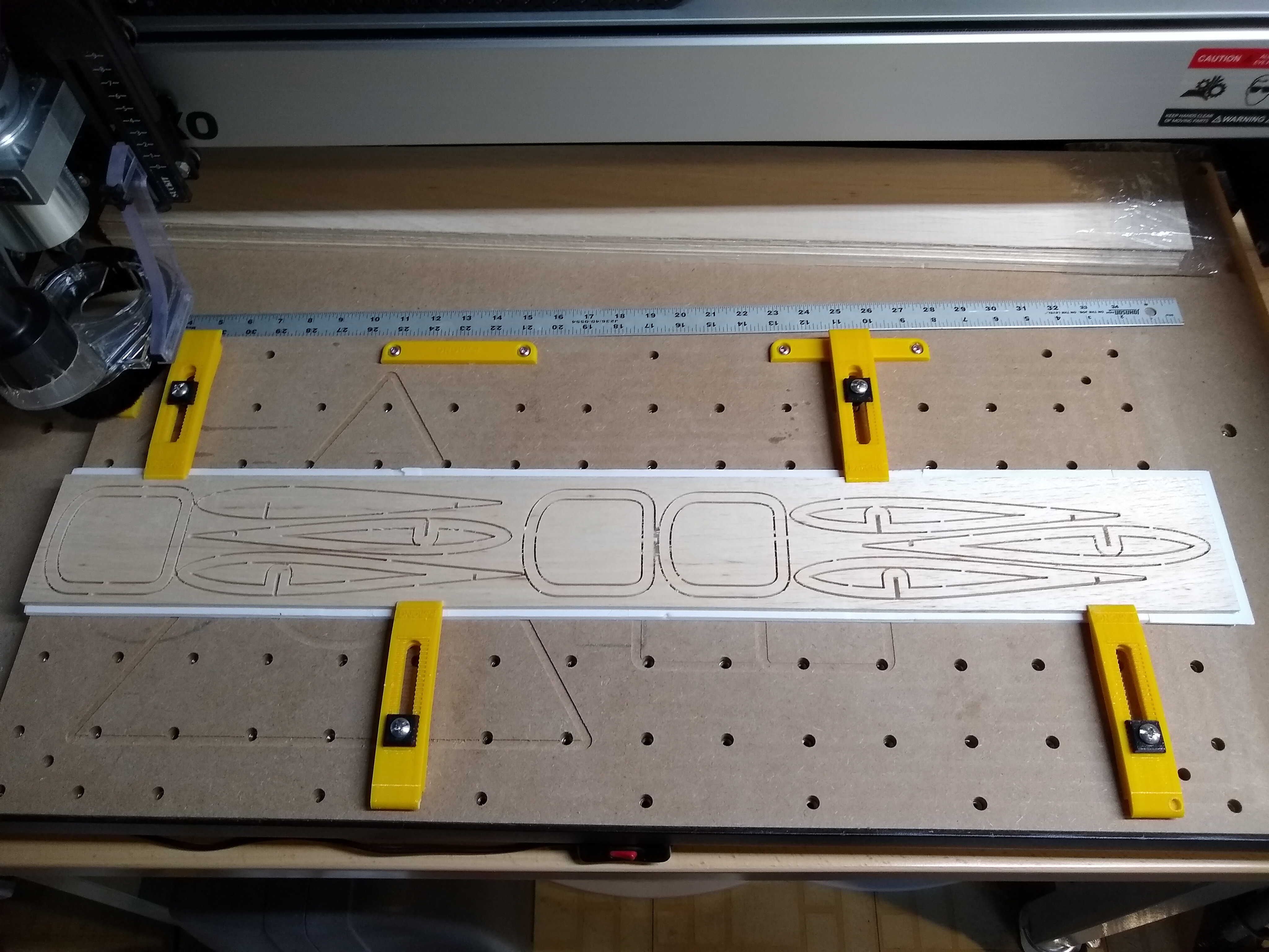
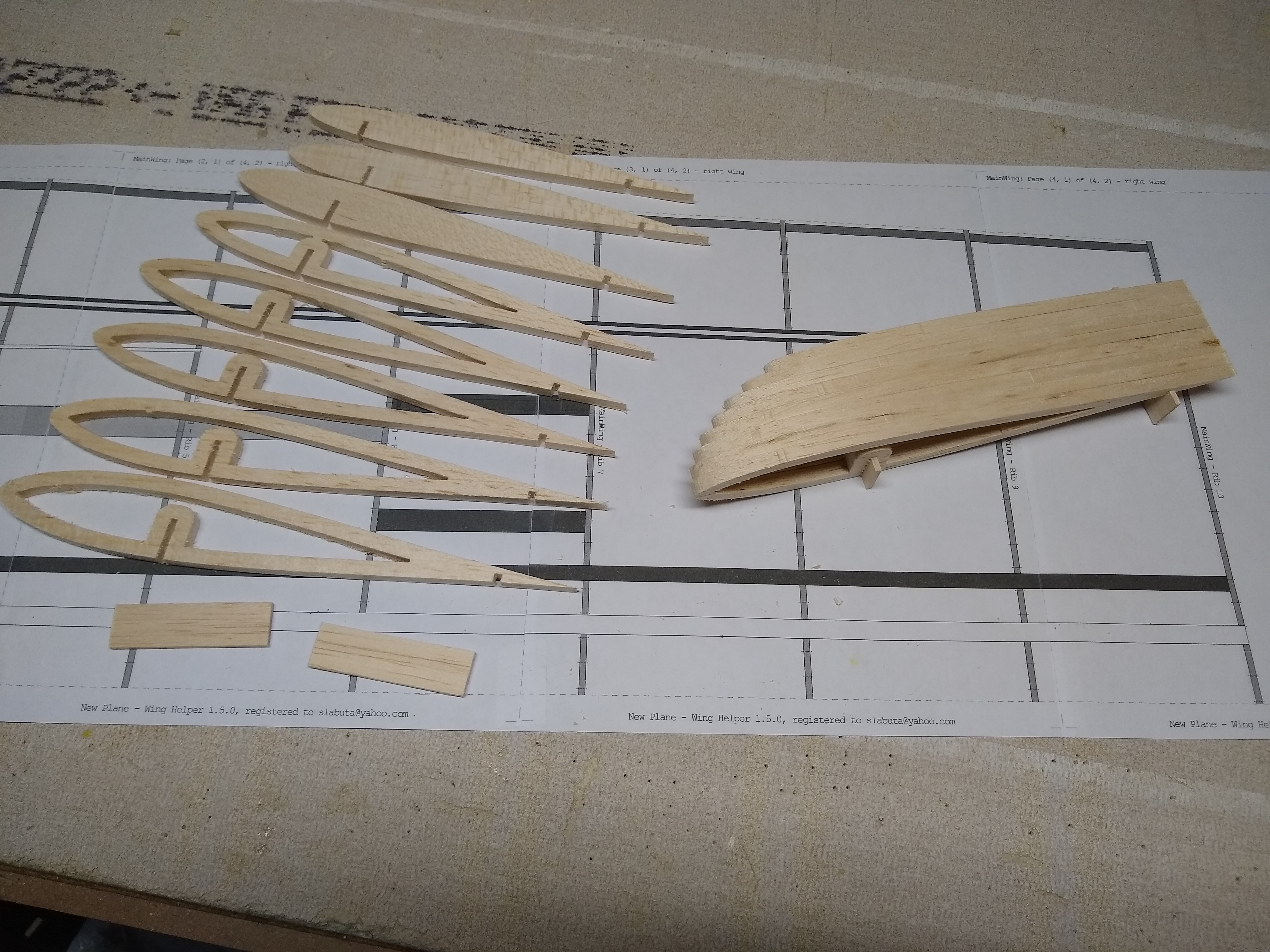
All parts were cut on my Shapeoko XL using Carbide Motion. The parts made from 3/32 balsa and 1/16 ply were cut using the tiny Carbide3D 1/32 flat endmill (#122). The ¼ in balsa was cut with a 1.5 mm flat endmill that has an 8mm cutting height. One thing I was worried about was breaking these small endmills in the waste board. What I did was use a piece of Dollar Tree foam board as a supplemental waste board. This worked fine but my depth of cuts needed to be extended some to cut all the way thru all of the parts. I guess the foam is not 100% flat. I used the tape and CA method to hold down the ply and it work well. I tried the same for the balsa, but it would break when trying to remove the tape after cutting, so I just clamped them down together. I copied the default softwood cutting settings for my endmills found in Carbide Create into the devCad software for use. I was able to increase the cutting speeds while cutting in Carbide Motion by at least 50% with no problems. Since I was more concerned with the quality of the cuts, I did not try to speed up any faster than this. I am sure I could probably still double the cutting speeds.

Assembly:
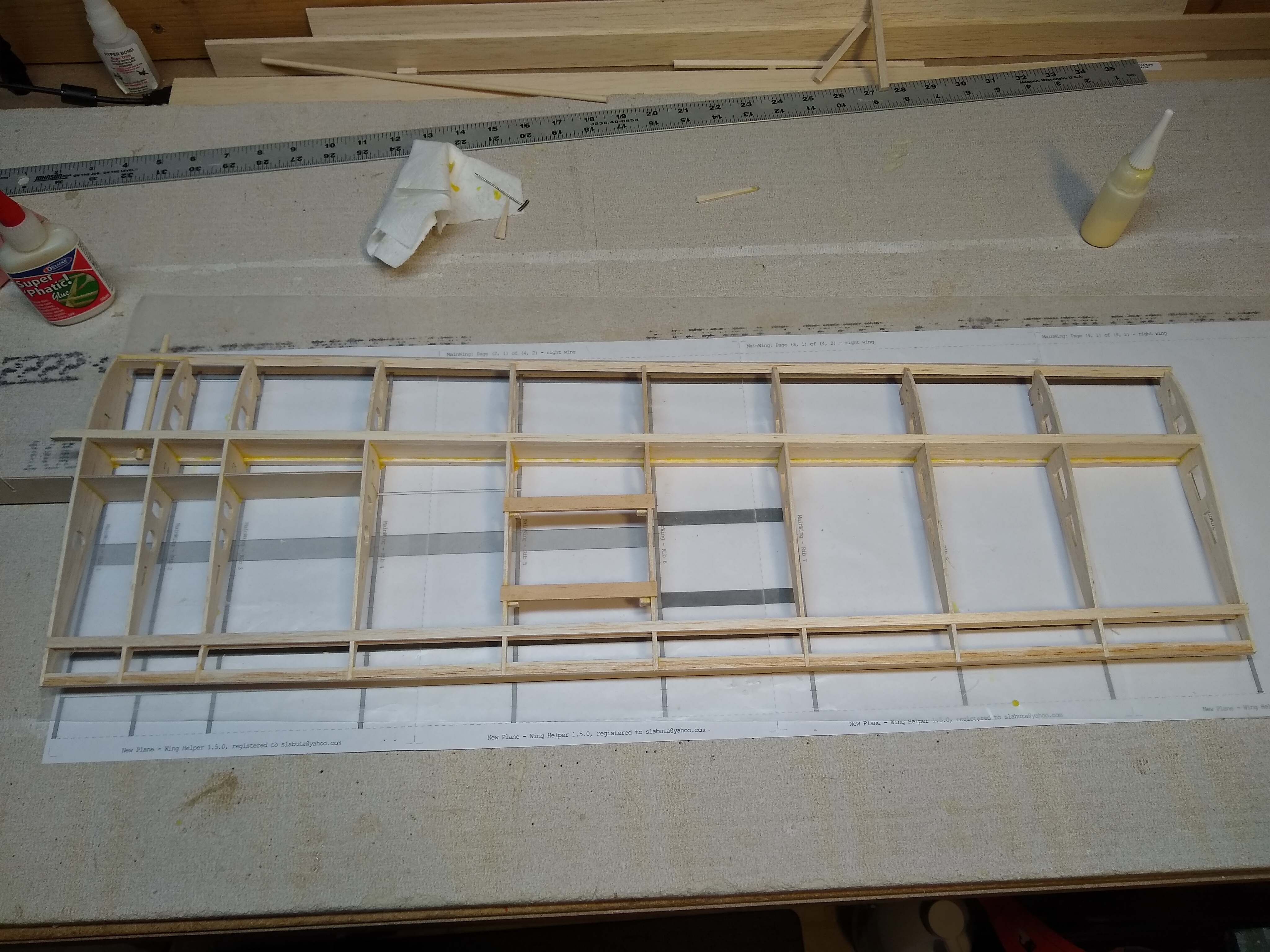
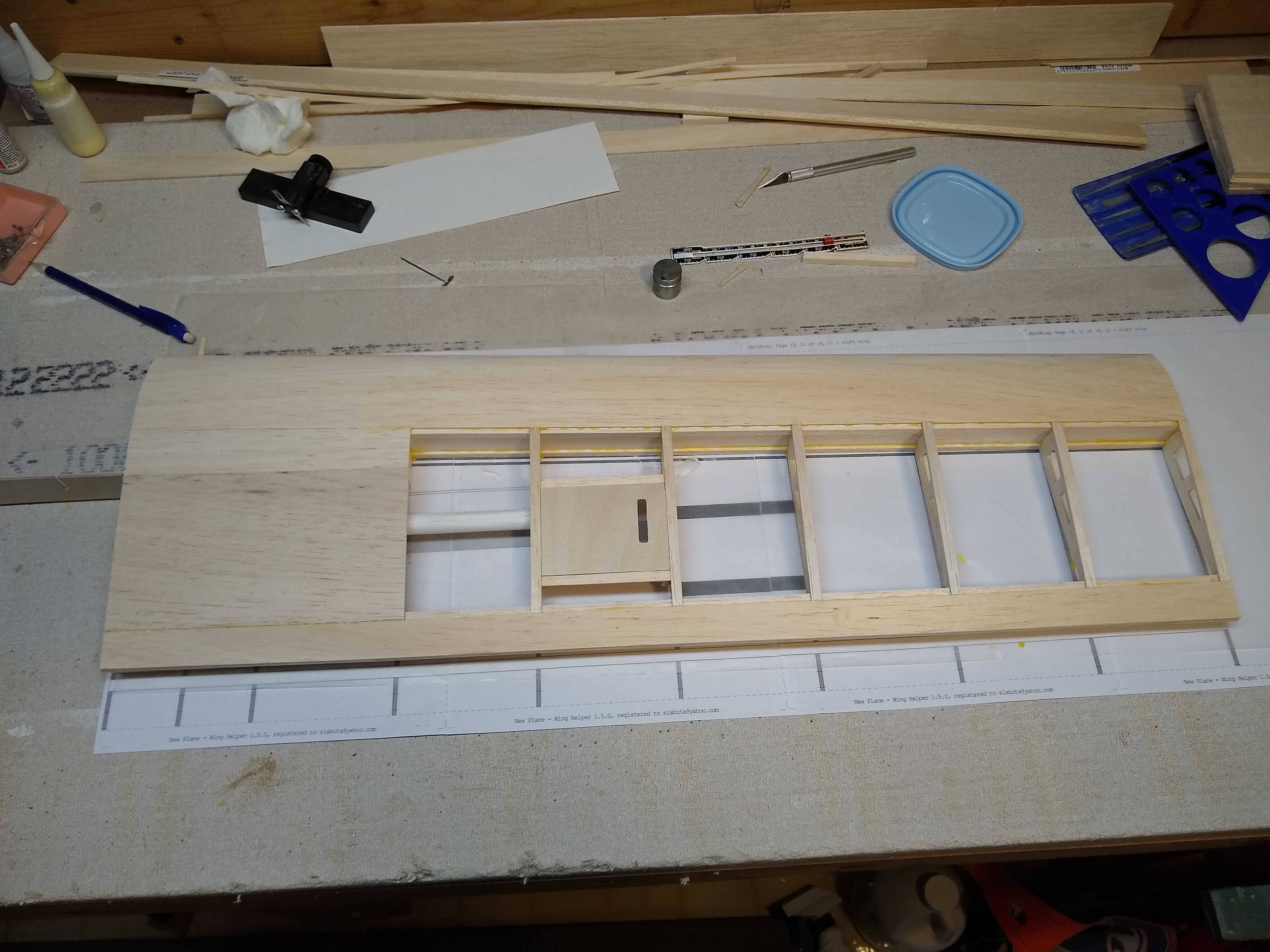
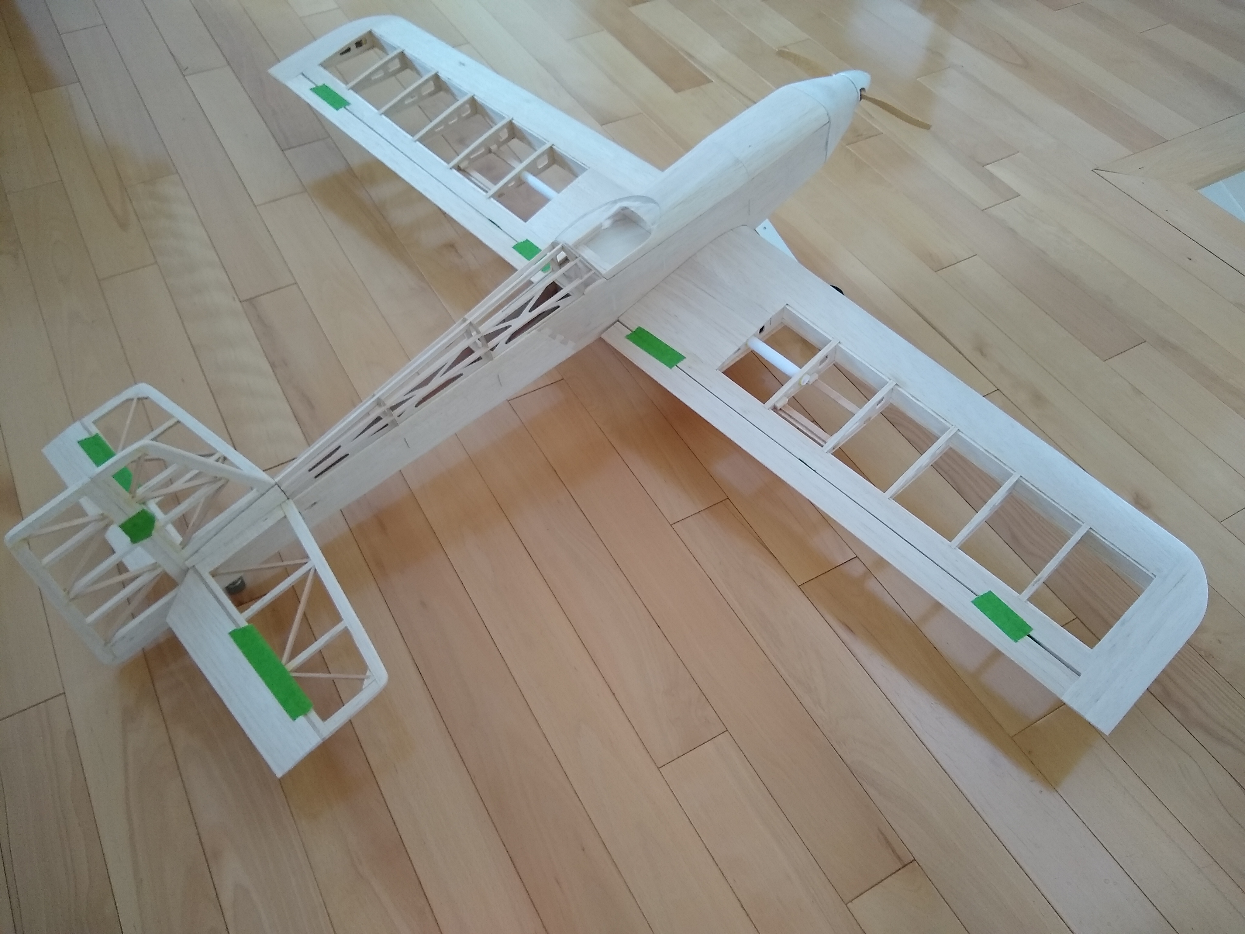
Started with the wing. It’s built mainly with the 3/32 balsa parts. Assemble the framework ½ wing at a time. Sheet the bottoms, join together and add the wing tips. Strictly glued together mainly with Titebond and some CA when a quick hold is needed.

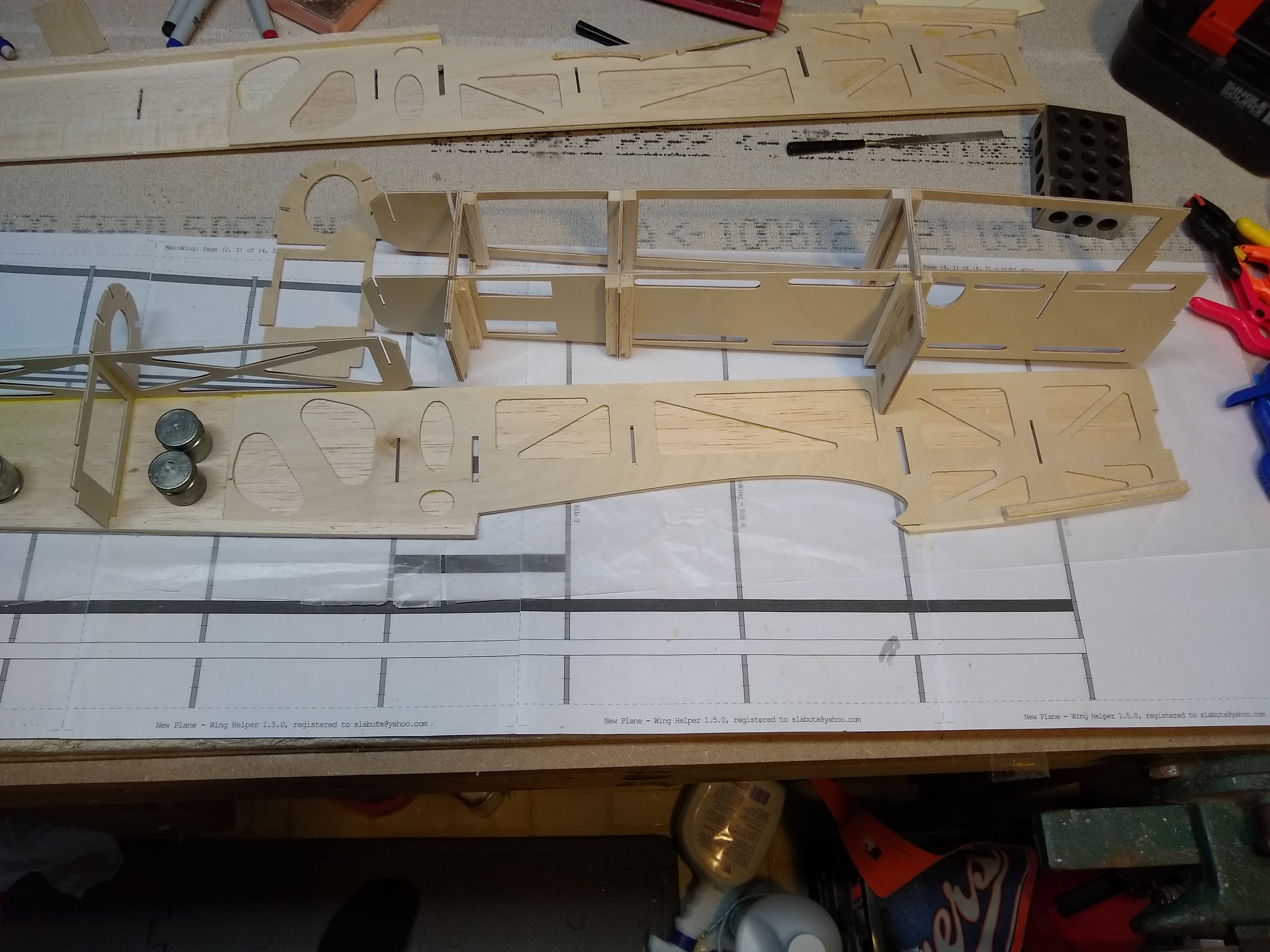
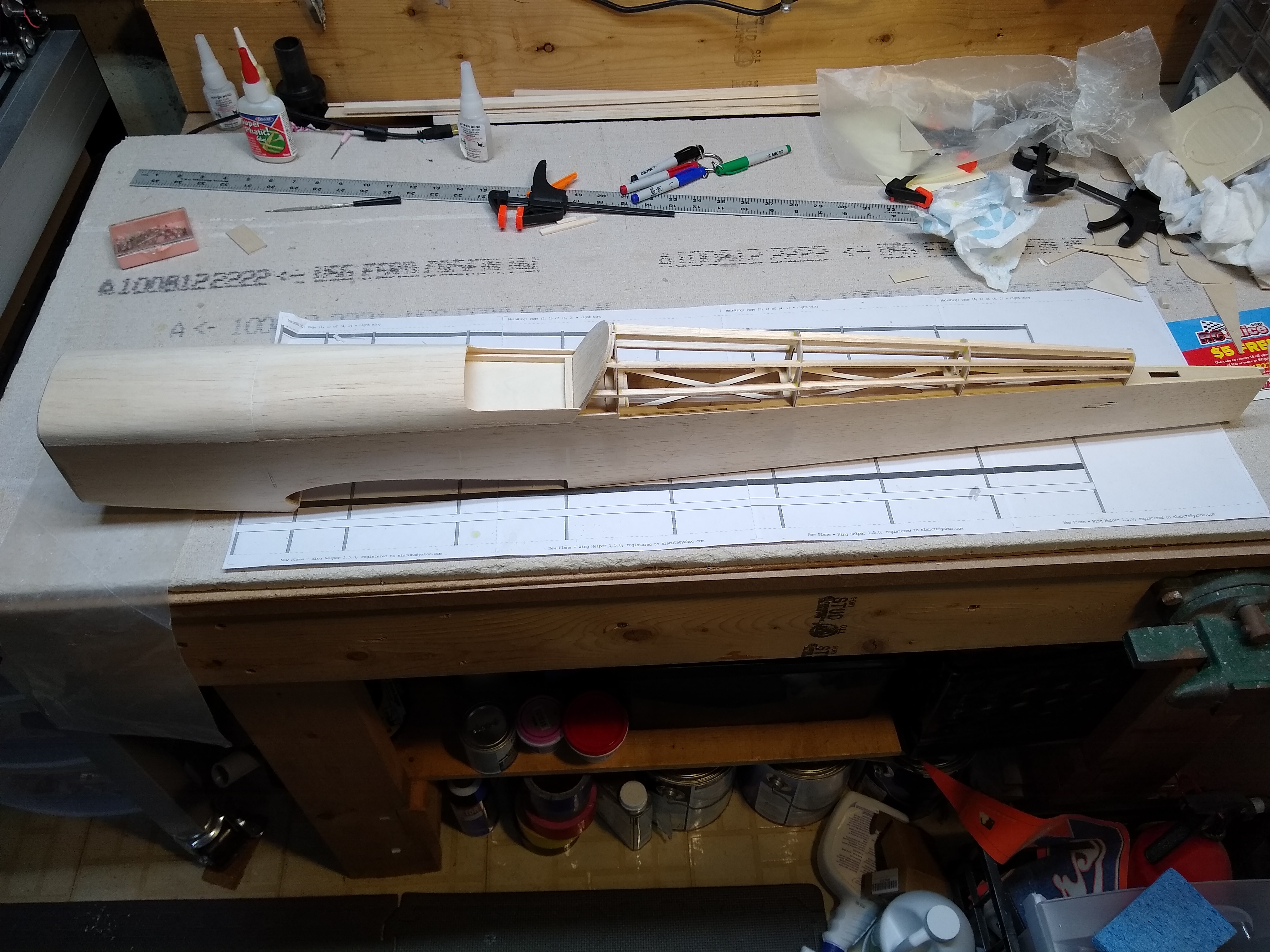
Fuselage assembly is a lot like the wings. A lot of self-aligning and tabs… Again glued together mainly with Titebond. Some CA and Epoxy as well.

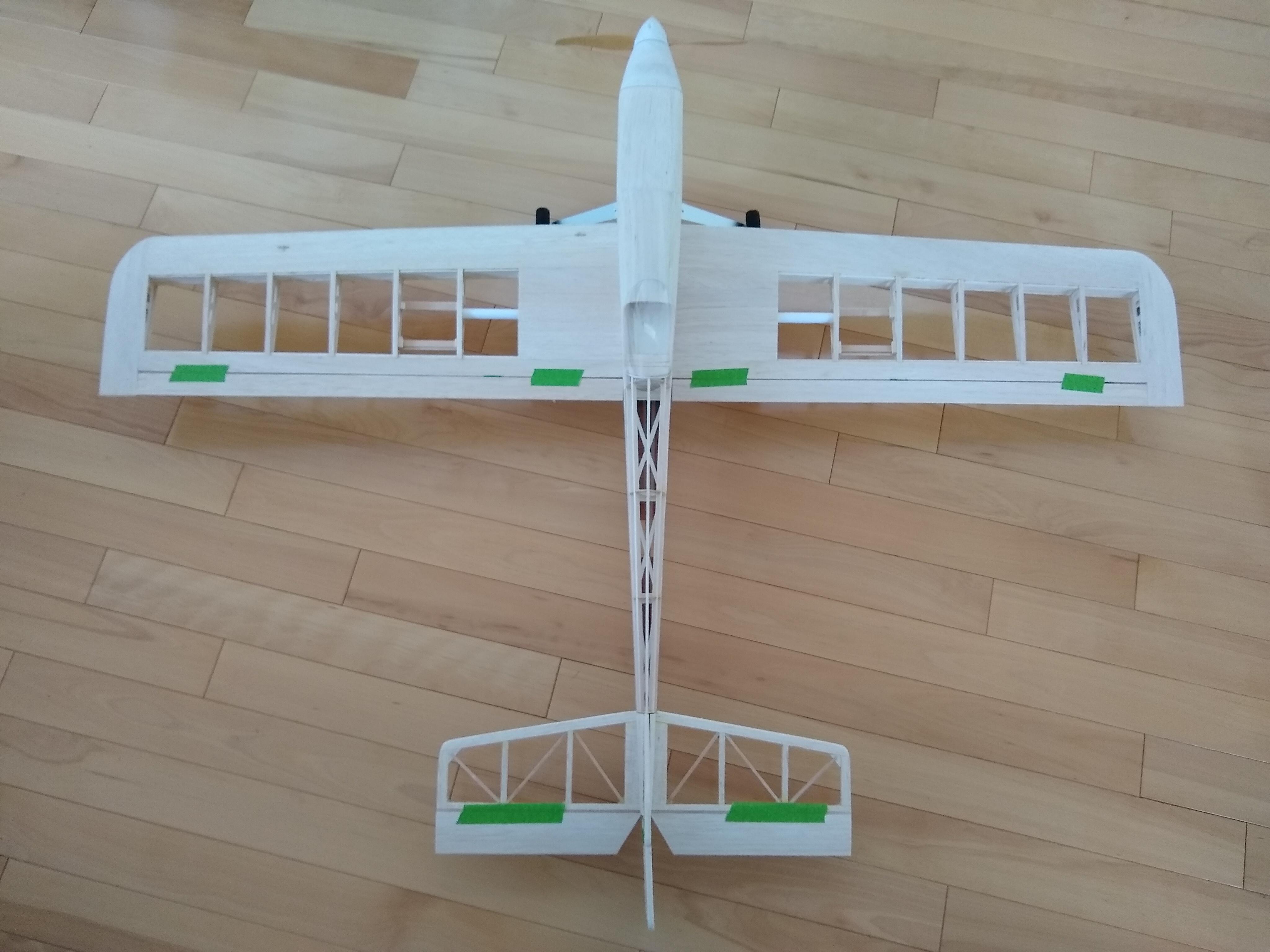
Final Assembled Structure:

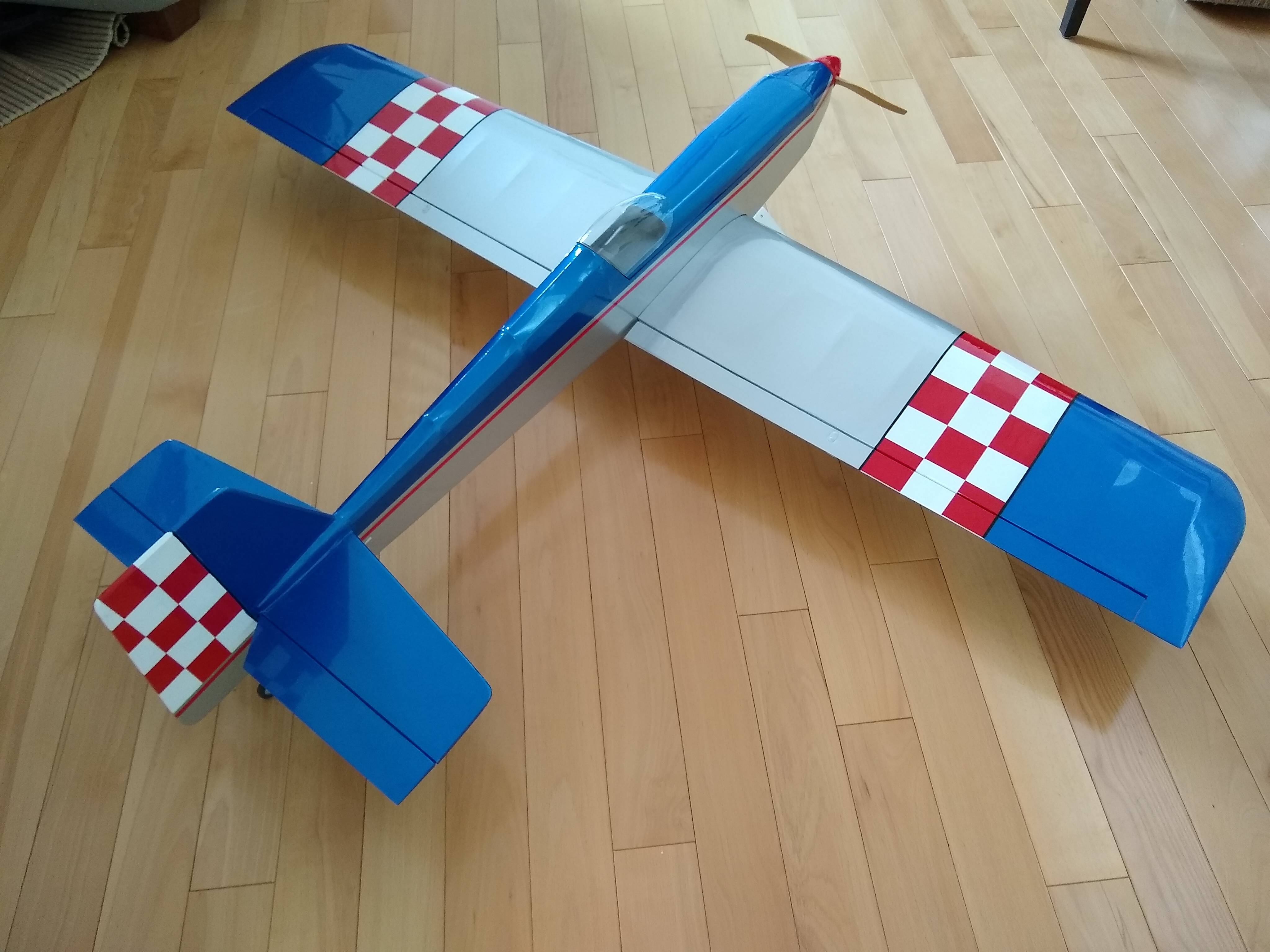
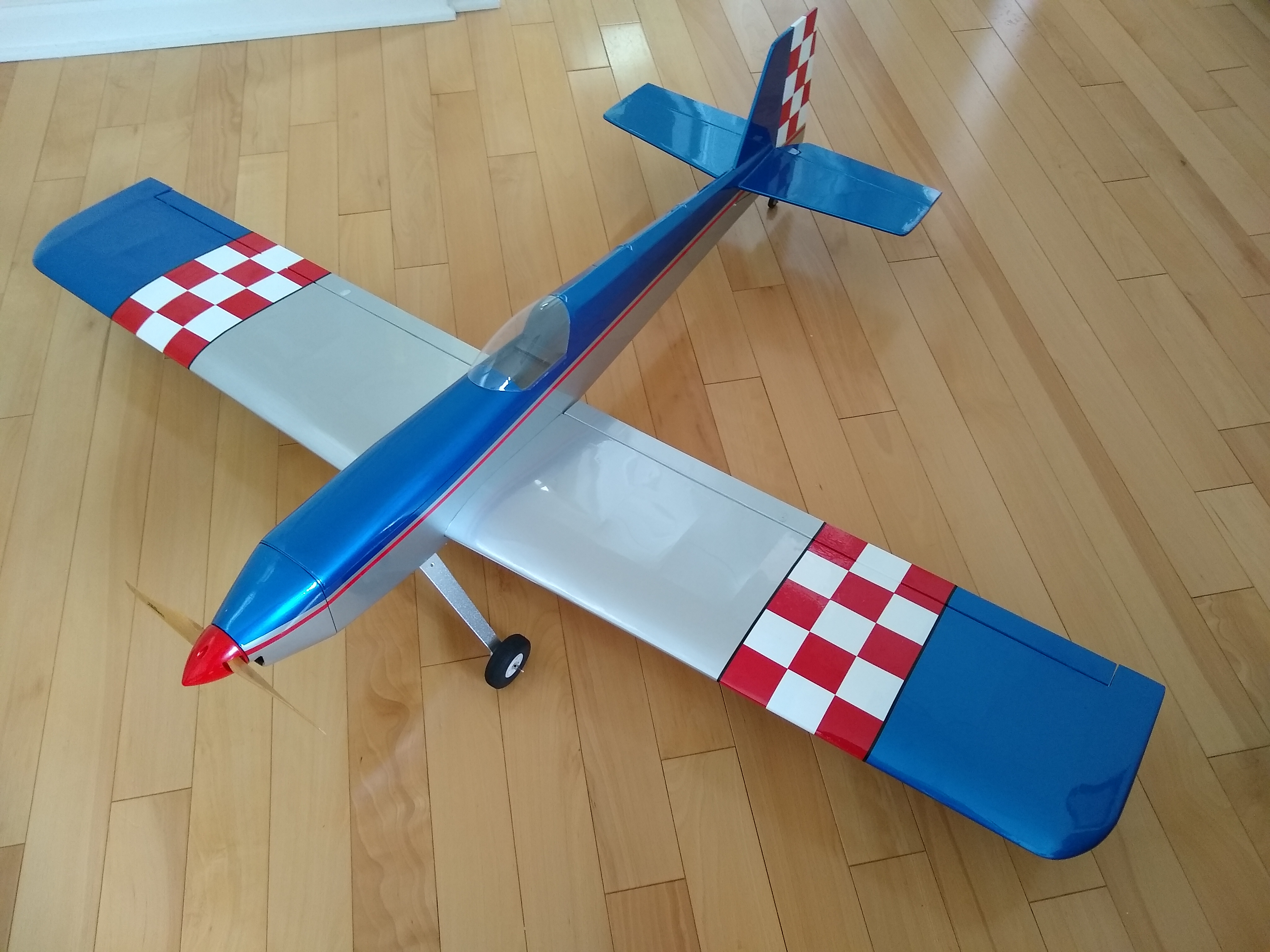
I used iron on covering for the finishing. It’s light weight plastic film with adhesive on the back. Final flying weight is a little under 4 lbs. I have now flown a couple of times and it flies pretty well! Still some tweaking to do, but I am sure I’ll be flying it for years to come.

After the first flight. Still in one piece!
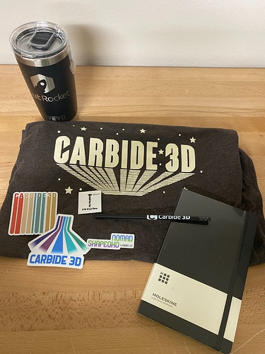
29 Likes

Well…, enjoy the clamps! :joy:

That is beyond cool. Awesome documentation and final product.

11 Likes

Awesome, just awesome…there could not have been a better way to kickstart this challenge, you have raised the bar, mister. :+1:

p.s. : btw it definitely qualifies.
p.p.s : nostalgia rush ! I have fond memories of going through those same steps, but without CAD/CNC

4 Likes

Mother of all rabbit holes…now I want to make one too :wink:
Nice project and end result sir! Thanks for the great documentation also :slight_smile:
A really cool display of what our machines can create!

2 Likes

I was going to participate and I still might, but I just decided to buy a set of Gator Tooth clamps haha.

1 Like

Same thoughts here. That is VERY impressive!

1 Like

Thanks for the kind comments everyone. I still want to see lots of entries here. I have seen many fantastic 2D to 3D type projects on Facebook and CutRocket. Artwork, furniture, tool organization, boxes, touch probe holders…

The RC world is definitely another “Rabbit Hole” of a hobby. I started about 15 years ago as a self taught backyard flyer and now I am the contest director at the local RC club. I bought a Shapeoko as a retirement present to continue my RC obsession and start another. Right now it’s the designing and fabrication that has my attention. I consider myself an only a slightly above average RC builder. There are many others out there that create flying works of art and scale replicas that look 100% identical to real planes. The best thing to do is to keep learning and keep trying new things!.

9 Likes

For folks who are interested in model aircraft, some potentially useful resources:

5 Likes