I’ve been making some mechanical keyboard cases and was pushing myself to minimize bit changes when I stumbled on a potentially novel, even controversial, idea for cutting miters. I’ve done two variations with it I thought I’d share.
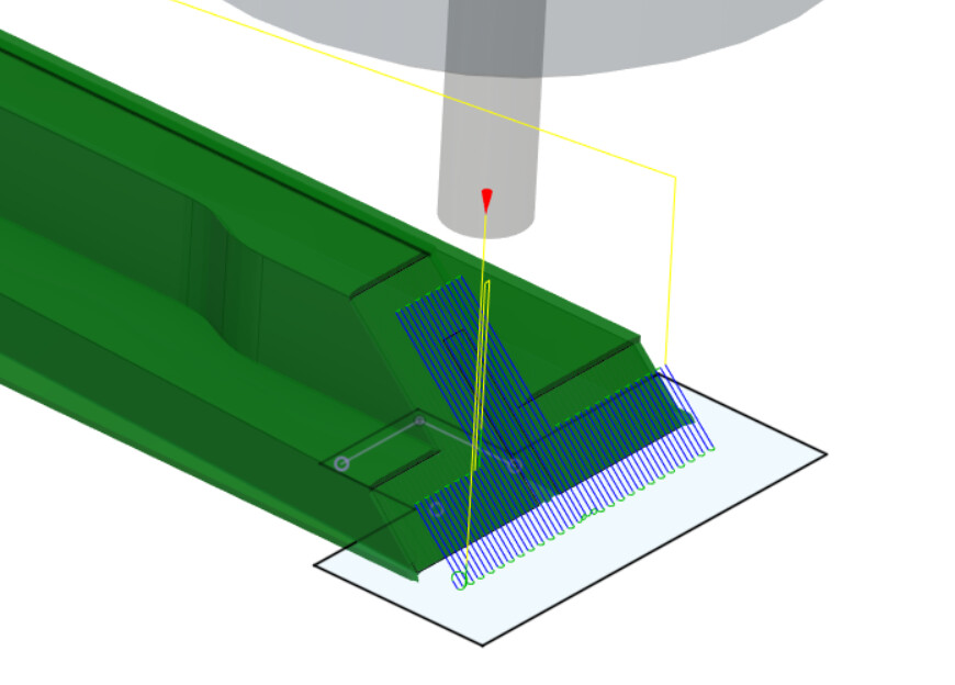
Here’s the big reveal: you just ramp up and down the mitered face with a parallel toolpath, miter joint facing up (vs. the intuitive way to cut this, with the miter joint facing laterally).
I wrestled with getting this quite right, as the parallel path wanted to initially ramp up the face, then move laterally onto the highest horizontal surface. It think my OG belt z-axis, the direction change, and machining both ways was enough to pull the bit slightly down into the finished surface. I posted on the Fusion360 forums for help which was… entertaining or just awful depending on my mental state. Despite the awful parts, it did confirm it was a machine issue, not Fusion360, and gave me some good ways to accomplish what I was after.
The short answer was to create an offset surface to constrain the parallel path to the miter itself, allowing my facing operation to take the top to the final height. The other thing I tried with great success was cutting miter key slots in situ vs. after the fact. For those unfamiliar, you usually complete your masterpiece (in this case a chess board), then you get to run it on a sled and fear blowing it at this late stage in the game!
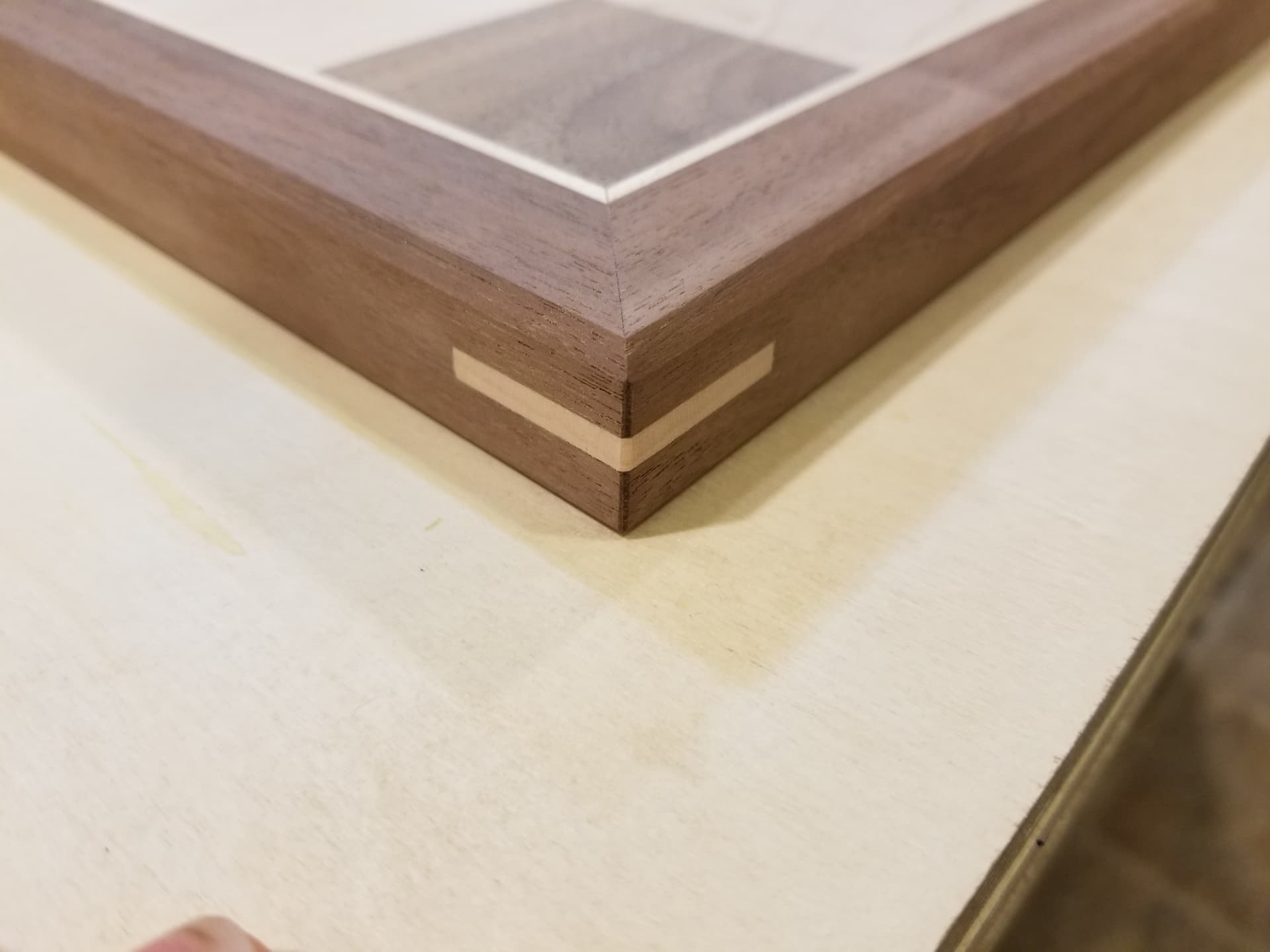
With those slots cut, you get some wood and insert it into the slots, then plane/sand flush. This adds a great deal of strength, as miter joints are end grain to end grain, and this adds a decent bit of face grain glue surface to the joint.
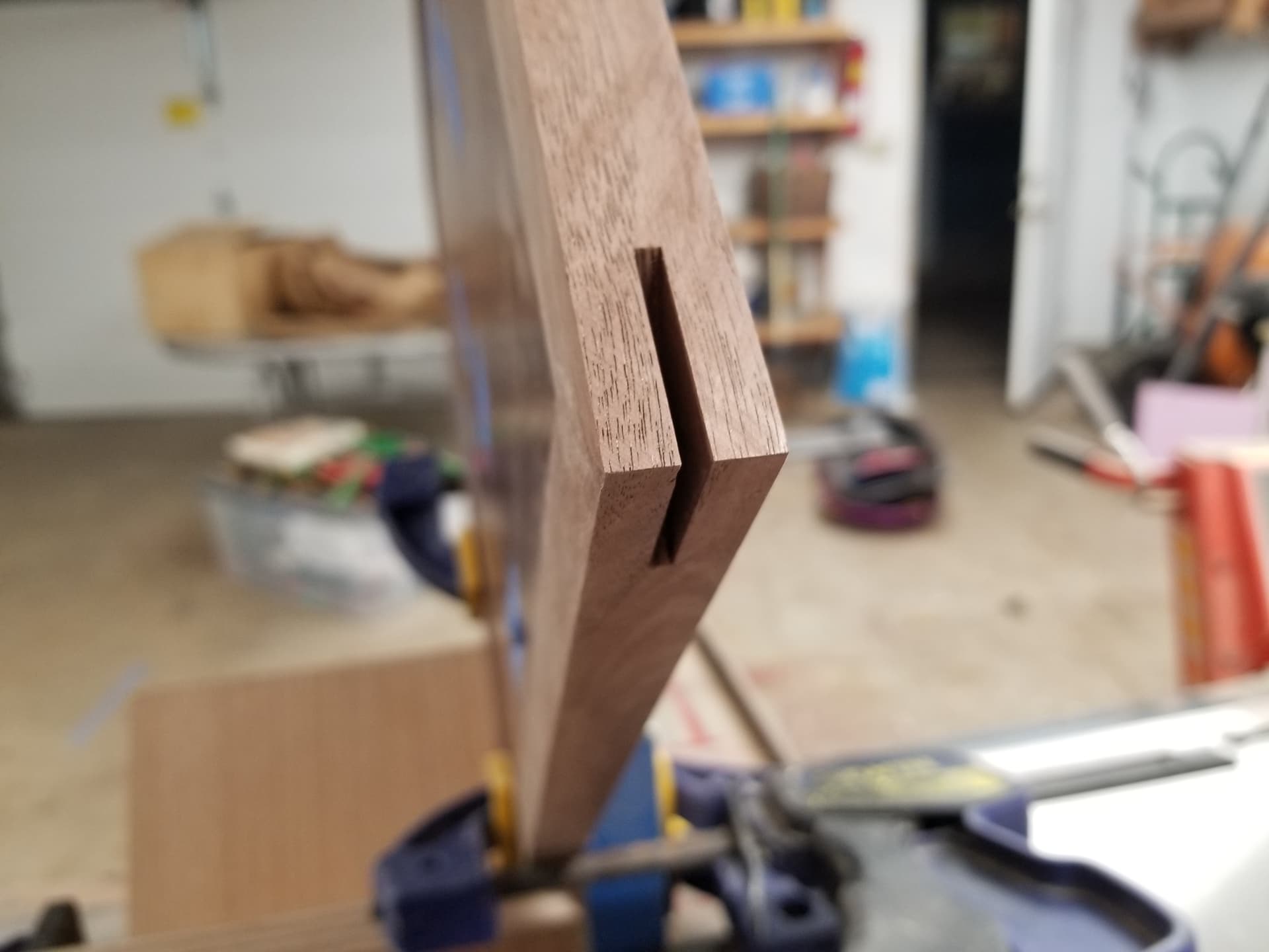
I wondered about just cutting them on the CNC, which this orientation allows for. Worked great! I used a 3d contour toolpath and a 2mm bit.
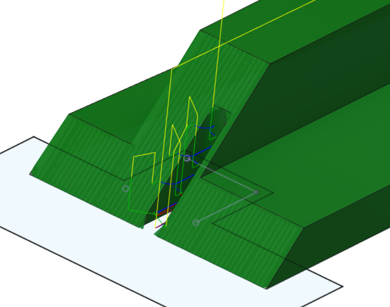
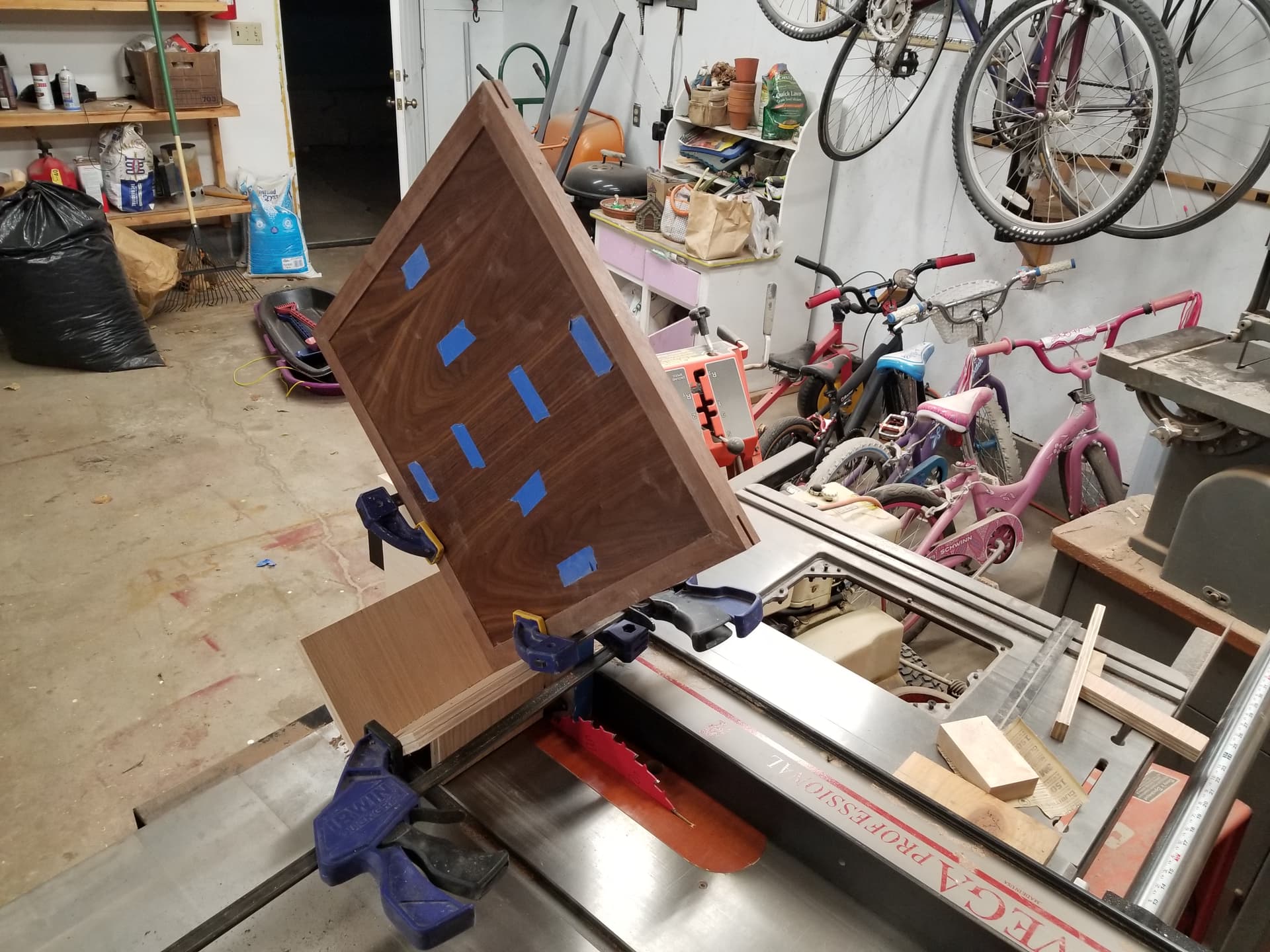
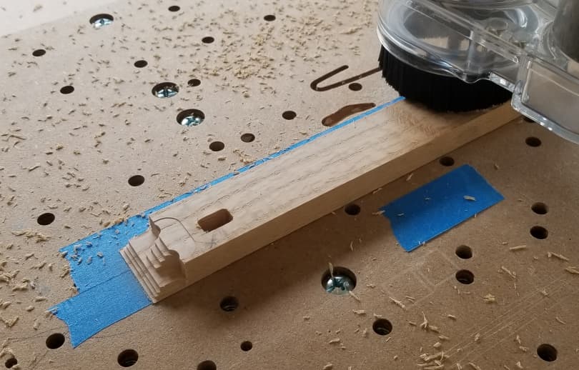
Here’s a couple of in process shots. I used an adaptive path to first stair step the miter, then let the parallel do its thing.
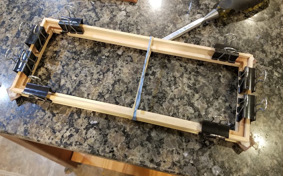
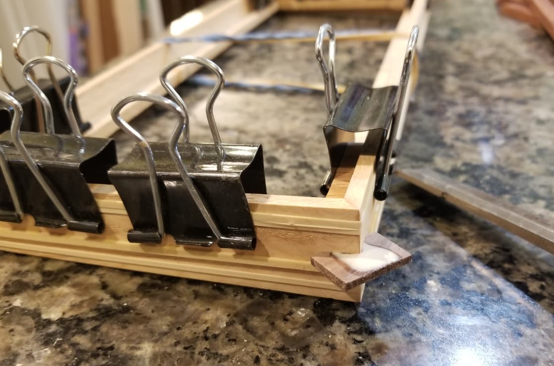
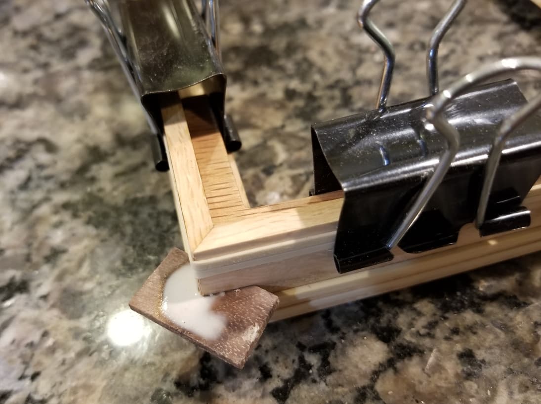
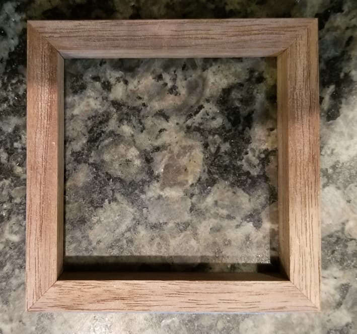
Here’s some pics of assembly. Because the miter key slots already exist, they can be used for alignment during glue up, which helps a ton. I also made some right angle braces to help keep everything in alignment. For smallish things, rubber bands work great, and the braces + binder clips are great for an added sense of security.
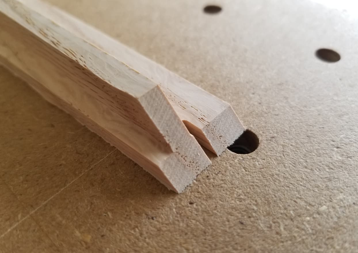
Depending on how deep you cut them, the only downside is you’ll either have to limit the width, or accept that the slot will be visible on the inside of the case due to how they are cut. For illustration:
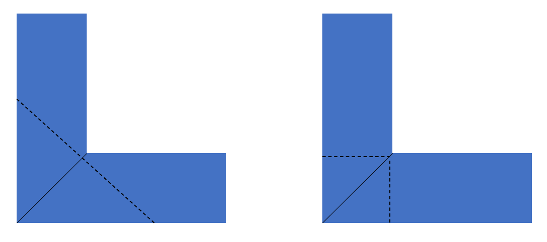
The joint on the left is what would typically be cut. Cutting these miter-up yields a square pocket in the piece on the right. Both have the same amount of “meat” left right at the inside of the miter joint, so you see what the max key size would be using each method. In addition, the pocket on the left will be fully filled with glue/wood. One could insert a square into the right pocket, however in my case I was fine with just a triangle, which left some of the pocket empty.
If you make a bigger key slot, you’ll see it from the inside, but it didn’t bother me and I think it looked kind of cool.
For a final idea, I was up late one night and incorporating the key into a piece came to me. This could fully fill the void and eliminate the need for separate keys. Here’s what I was thinking out loud on my whiteboard.
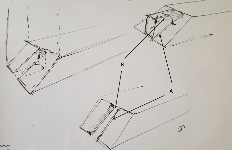
In addition to not needing to make keys, it also has the advantage of registering 90 deg corners, at least in theory. The face of that “nub” will press on the inside face of the groove. One downside is the joint won’t be symmetric. The key will only be visible on one face per corner, however one could make pieces that are male/male and two that are female/female, and at least the piece overall would be symmetric. I also haven’t wrapped my mind around if this is e.g. 1/2 the strength of a key that spans both pieces.
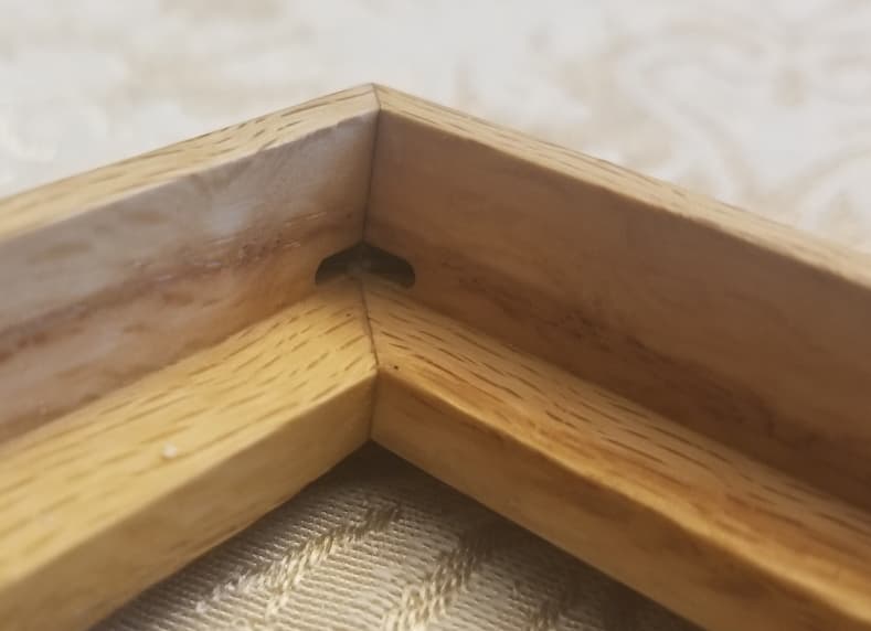
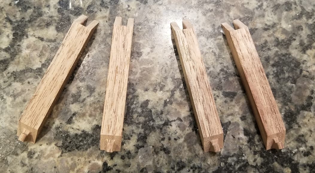
I could foresee that both the male/female pieces would end up with concave radii due to the bit and would therefore require matching convex radii on the mating geometry for clearance (labeled A and B here). That said, the way CAD terminates two fillets made for some weird geometry, so ultimately I ended up cutting a portion out of the male bit to preserve the sharp intersection of the inside flat surface of the frame and the miter itself. Here’s what they ended up looking like:
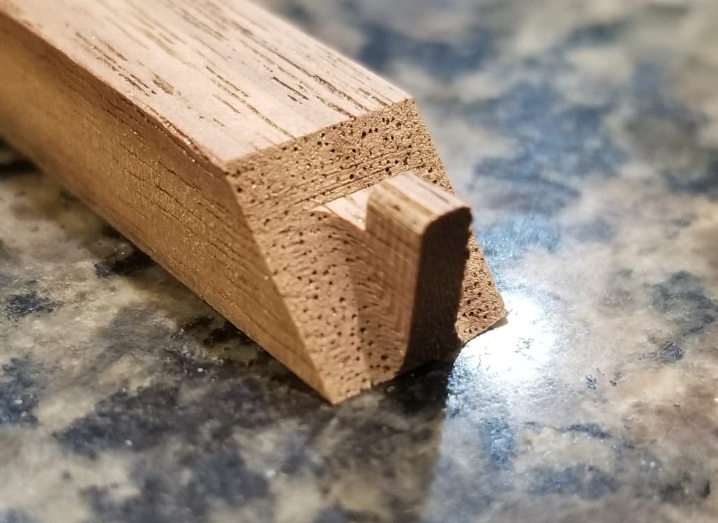
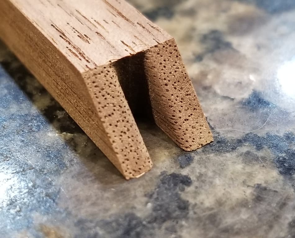
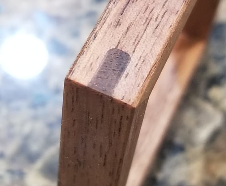
I was… freaking thrilled. This worked so well and the miters were some of the best I’ve ever made via any method. There is a hairline gap between the built-in key and the slot which is either due to slight machine inconsistencies or perhaps flex in these small pieces during cutting. They are only ~8mm wide, and this would be the surface adhered to my waste board using tape/glue. It was easily filled with glue and sawdust (look hard at the left side of the picture of the below).
While we’re at it, here’s a cool site with a ton of various CNC joints. I didn’t see the above, but it has a bunch other others I’m now pondering and might be useful to others here.
Alright, hope that helps and maybe gives some cool ideas to others!
