I am trying to cut some mating pieces with my 4 XXL, I would like to cut some dovetail joints in two pieces that can then be assembled together - and what is happening is that even though I am cutting the male and female parts side by side there is quite a bit of space around the dovetail when I put them together.
I though that it could be the machine needed to be calibrated for belt stretch so through the process I dialed in the calibration to get my x and y dimensions with .01 of the design. I cut a square pocket in some material to be 2x2 inches and measured it to be 1.99x1.98.
Even after the calibration I am still getting space around the dovetail and the joint is not tight.
In the design the parts are exactly the same size, however in reality the male and female parts are off by a considerable amount.
I have used a low-angle dovetail bit to design & make some plywood boxes & drawers.
It took very careful design & test cutting to dial-in/adjust the vector paths for the dovetail cuts. The depth of the cuts also have to be precise for a good fit - so a flat bed & stock material tight to it are required.
I also used an endmill bit to cleanout most of the dovetail fingers/grooves before using the dovetail to set the beveled edges. This made it easier to consistently make the precise geometry as the dovetail didn’t have to clean out it’s full cutting width of material.
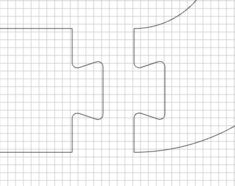
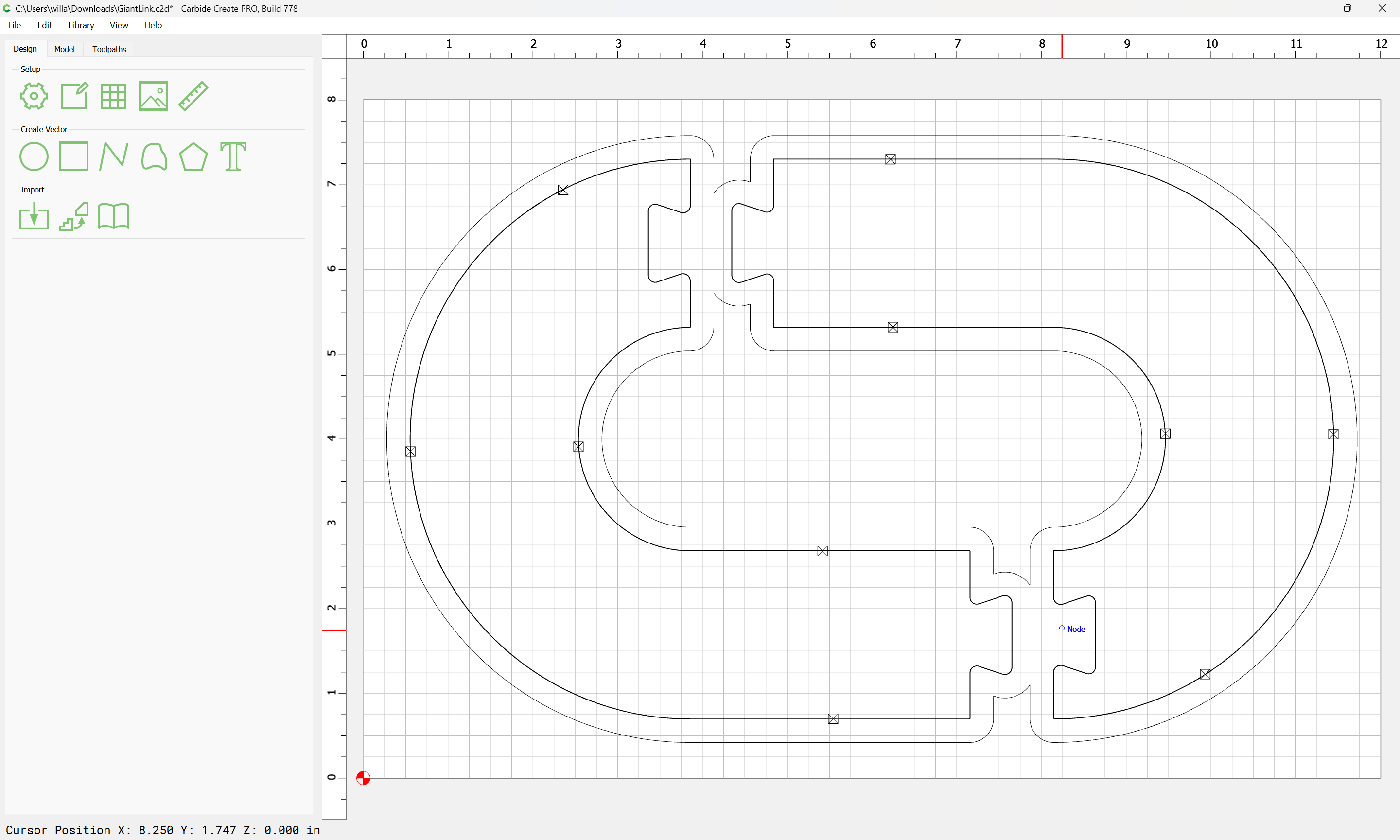
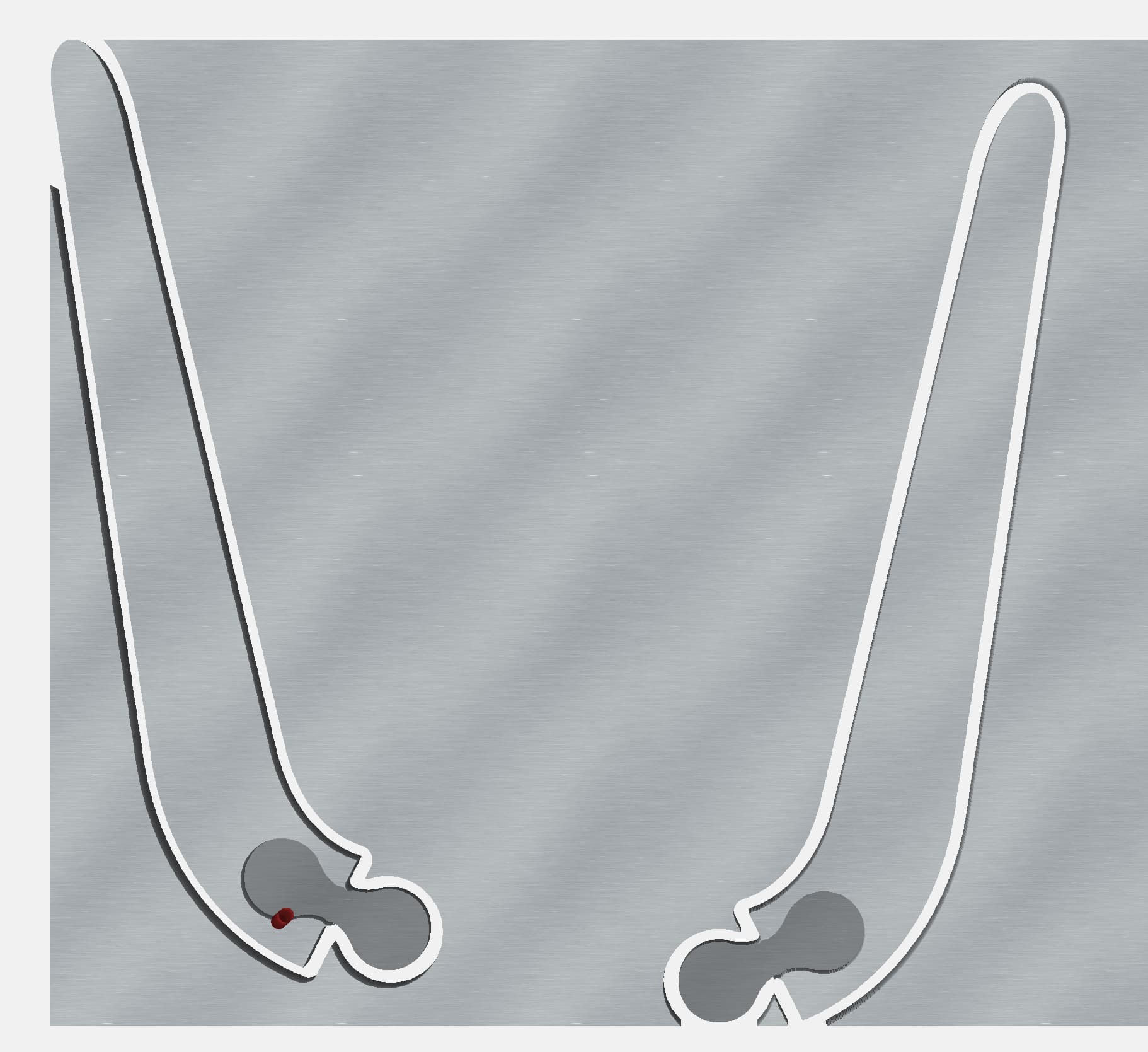
Here is the joint I’m trying to cut, when completed the male part has apx 1/16-1/8 all the way around. When I get back to the shop I will post some pics. For reference the dovetail is 1 inch at the widest point.
It is important that everything be configured and described correctly, and that the machine be in good condition and running well, and if a belt-drive machine, that it be calibrated for belt stretch, and that any toolpath/geometry take into account the runout of the spindle.
A further consideration is that the tool you are using will not fit into your design:
and assuming that the 0.5" thickness is accurate, that is just barely within the cutting abilities of that tool.
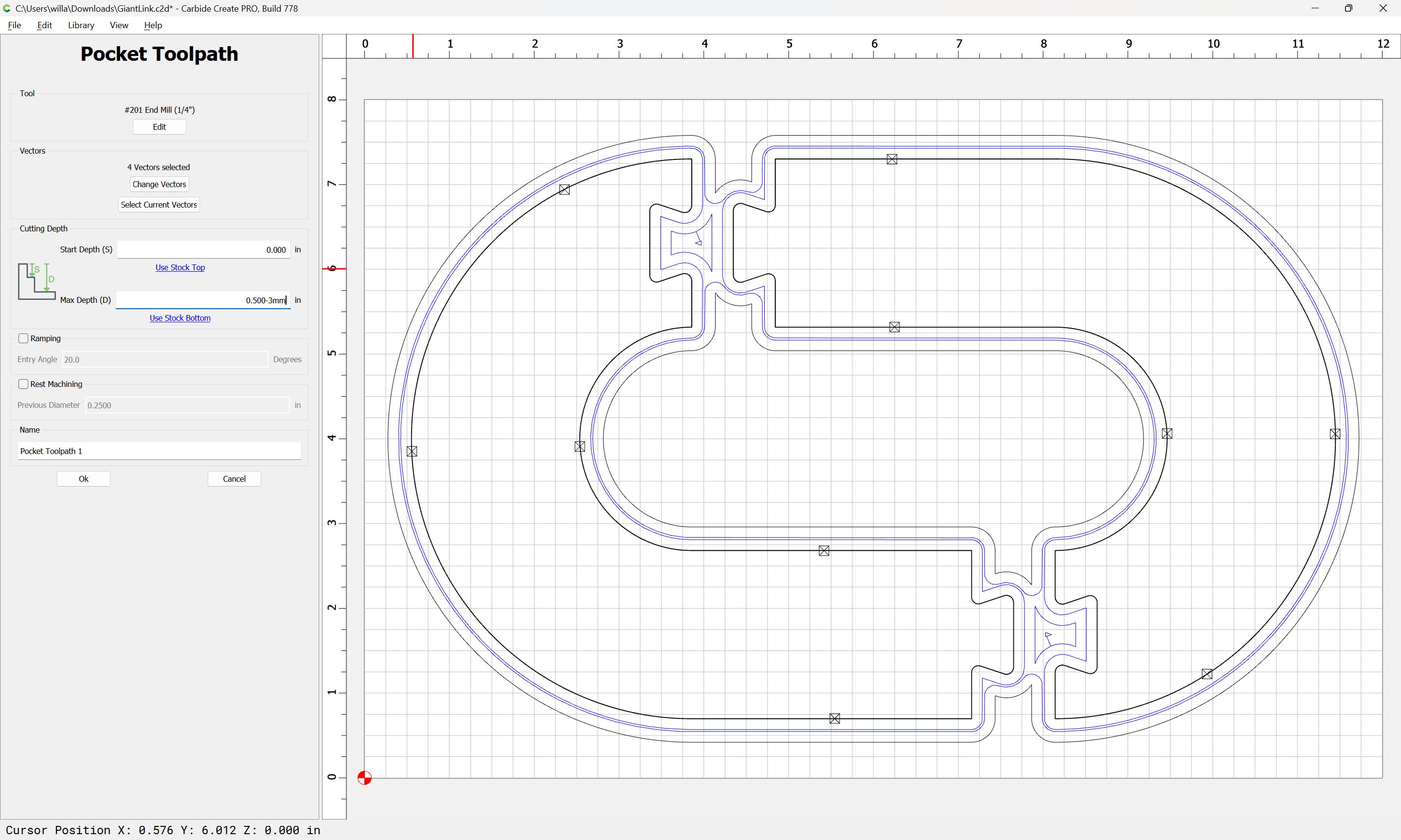
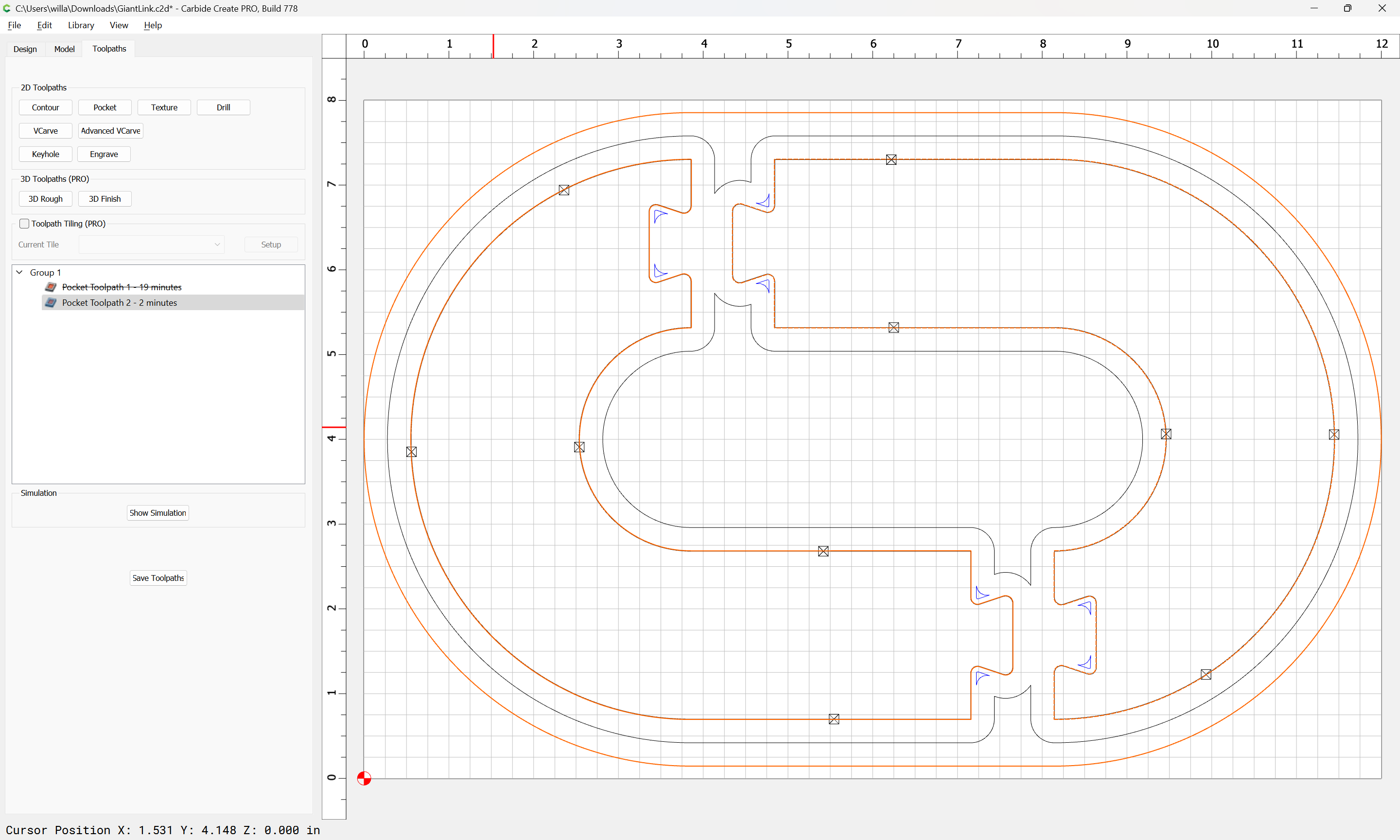
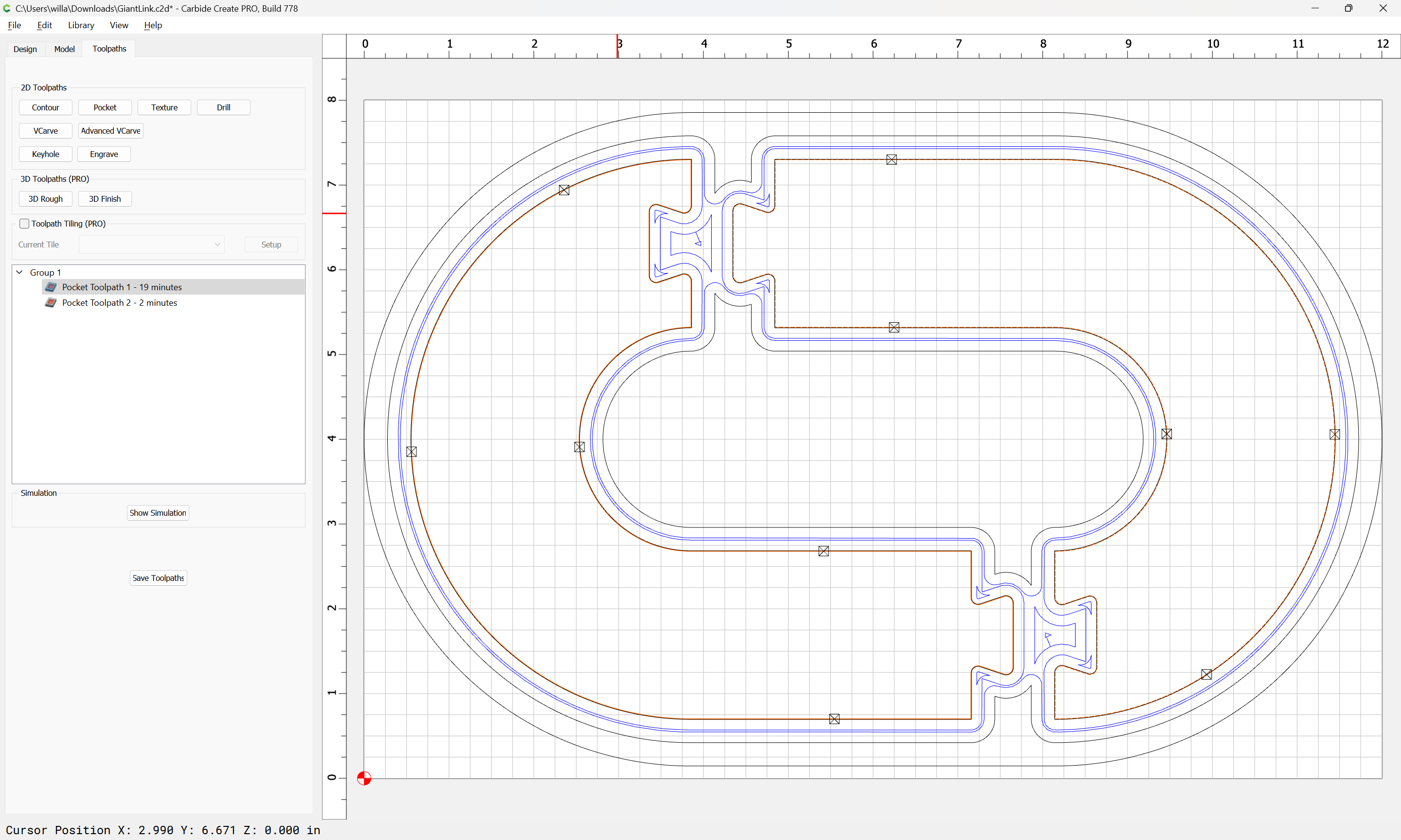
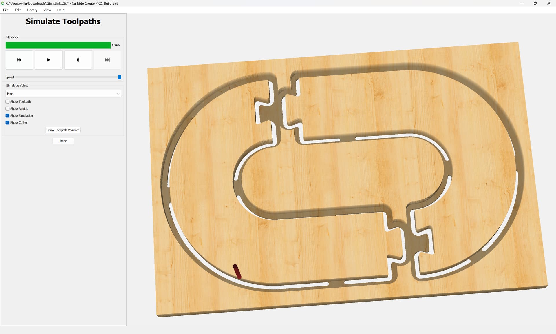
That said, this is a lot of material to remove with a 1/8" diameter tool, so we will assume Carbide Create Pro, start with a #201, and then use REST machining to remove the material which it cannot reach, and then the #102 to make a finishing pass.
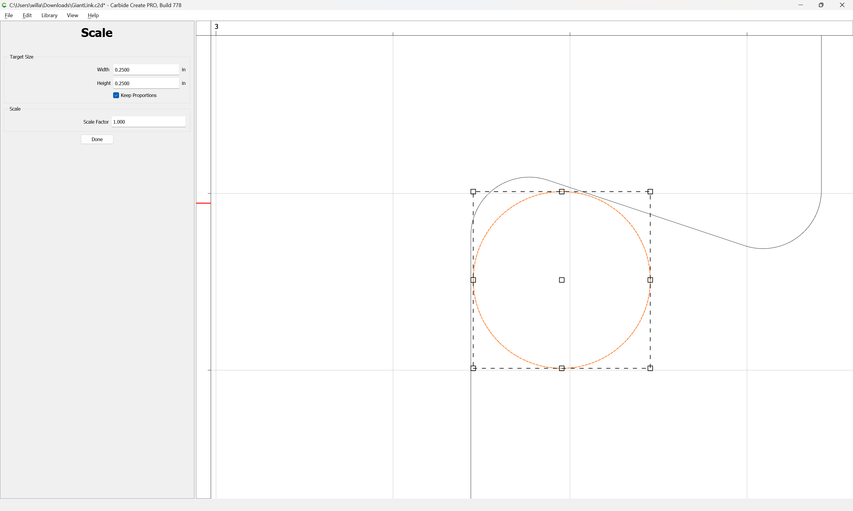
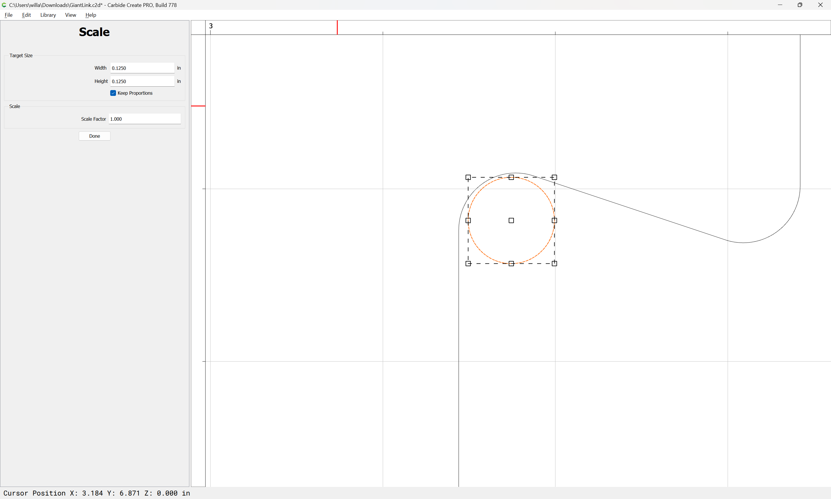
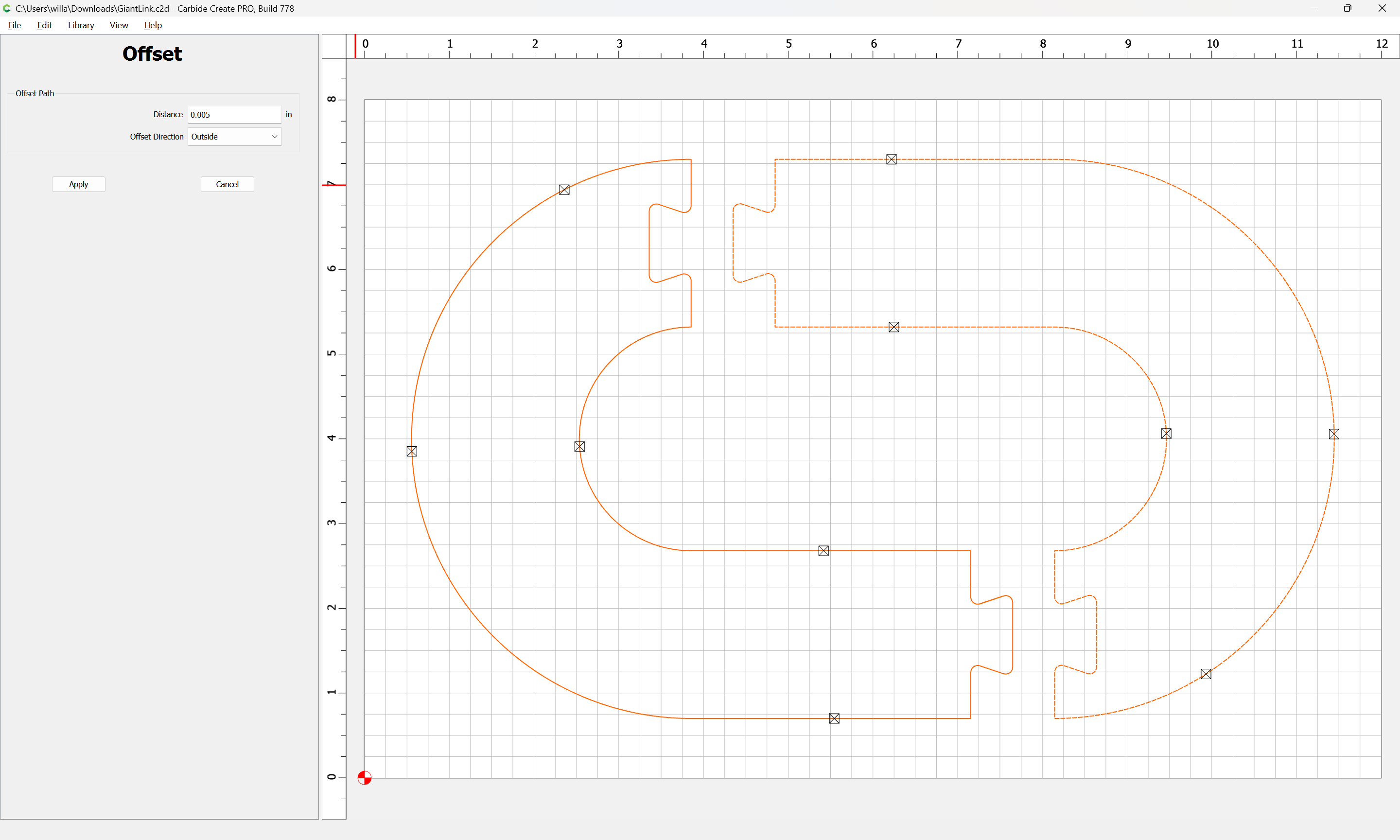
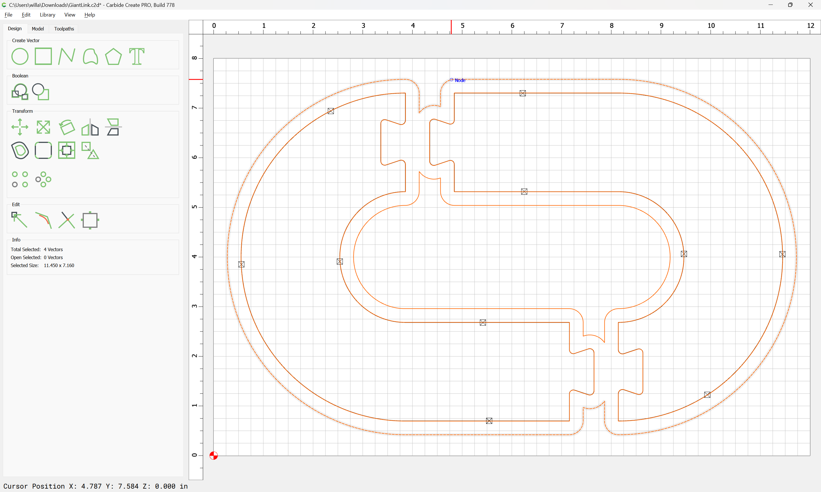
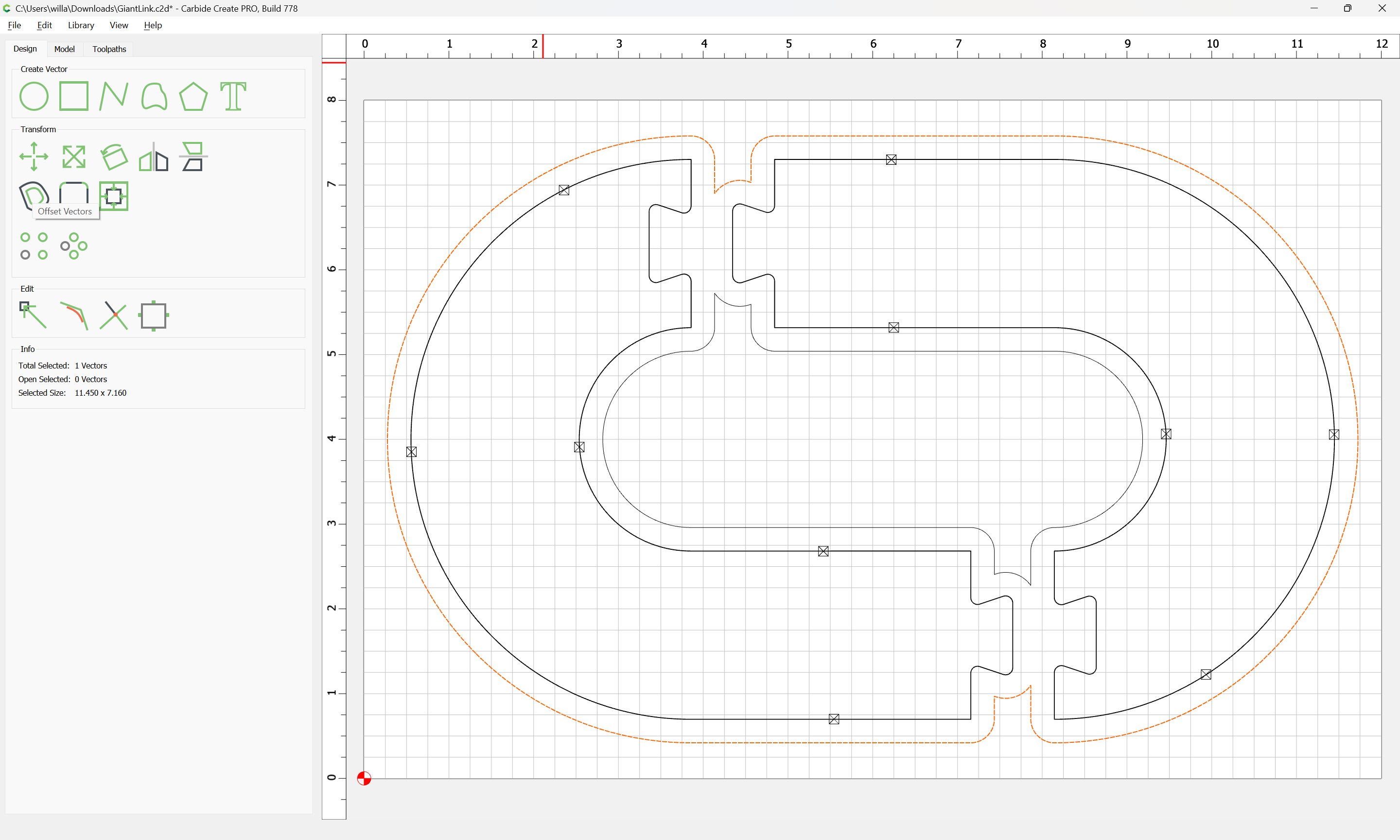
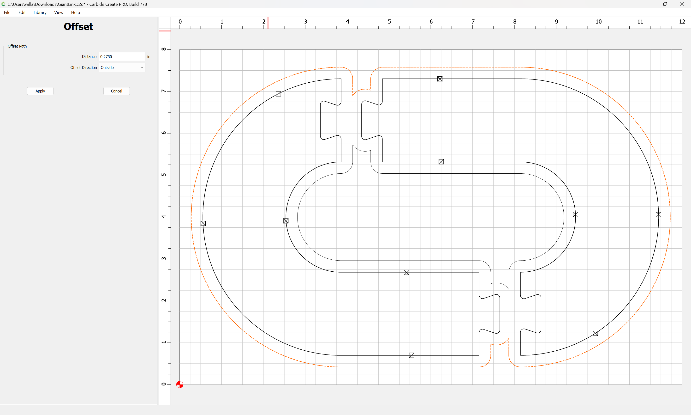
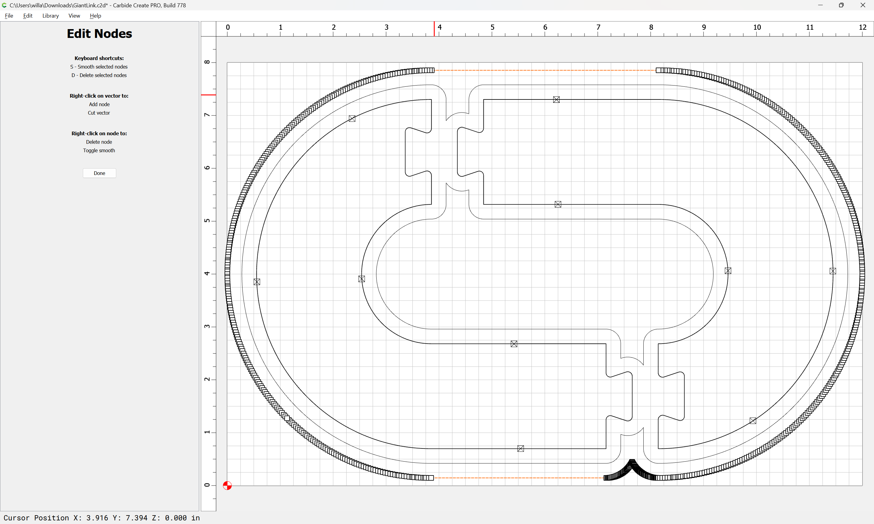
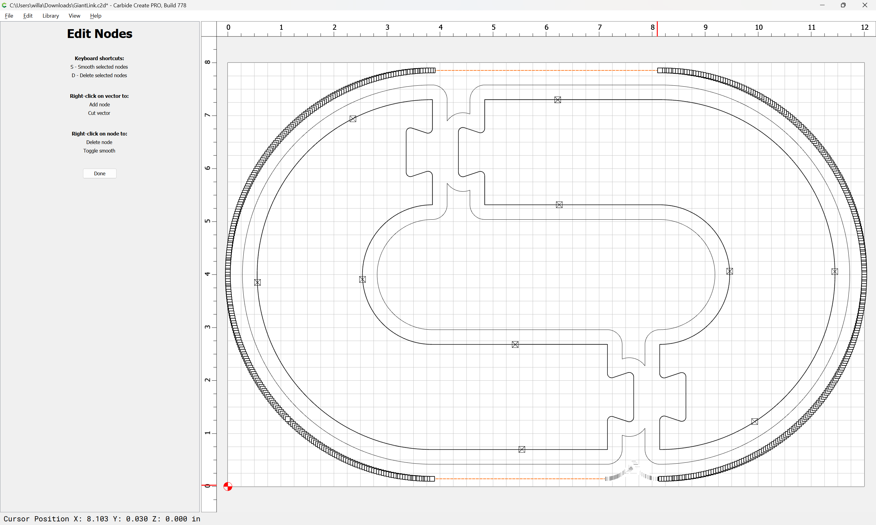
My recommendation would be to offset by a bit more than any defect which you are seeing (but at least chipload):
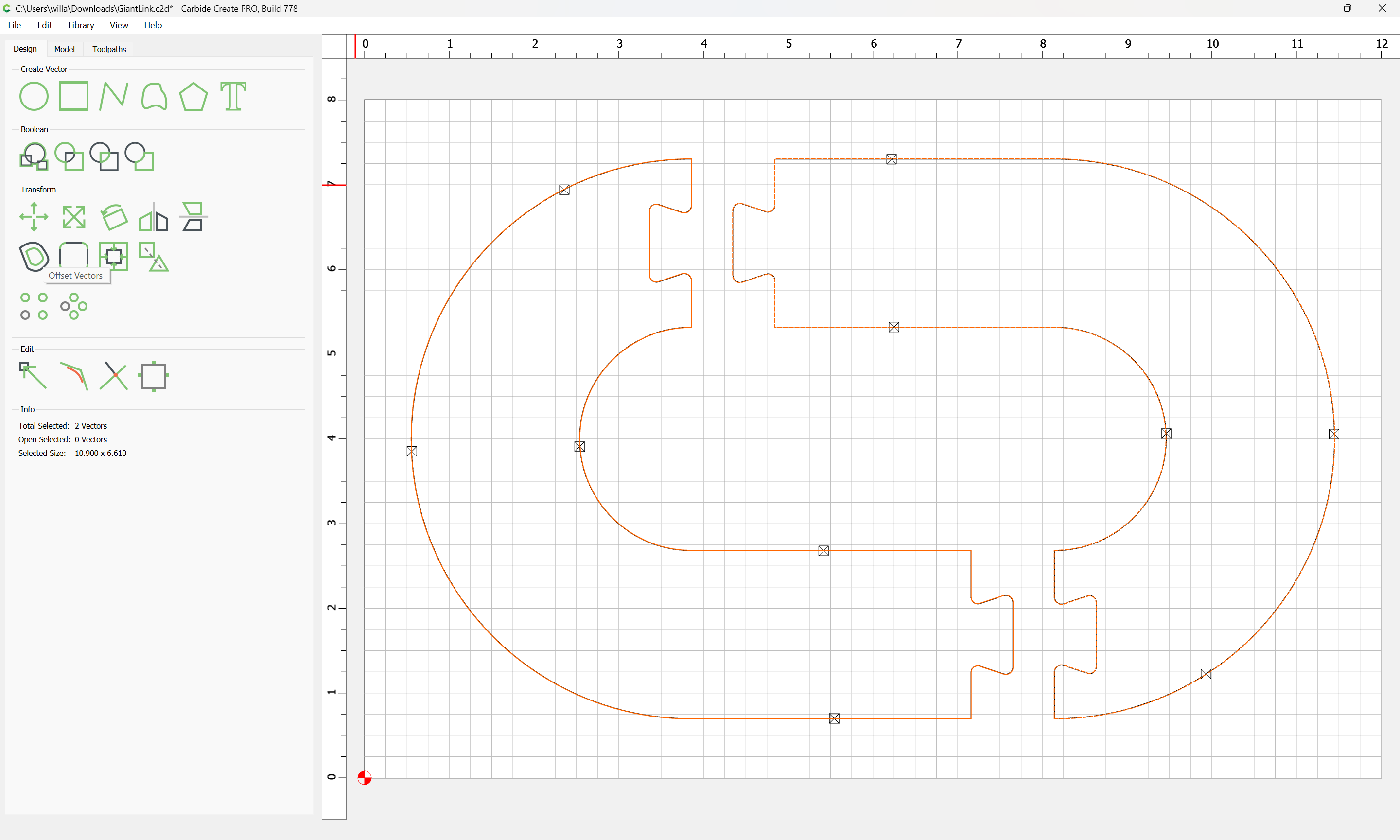
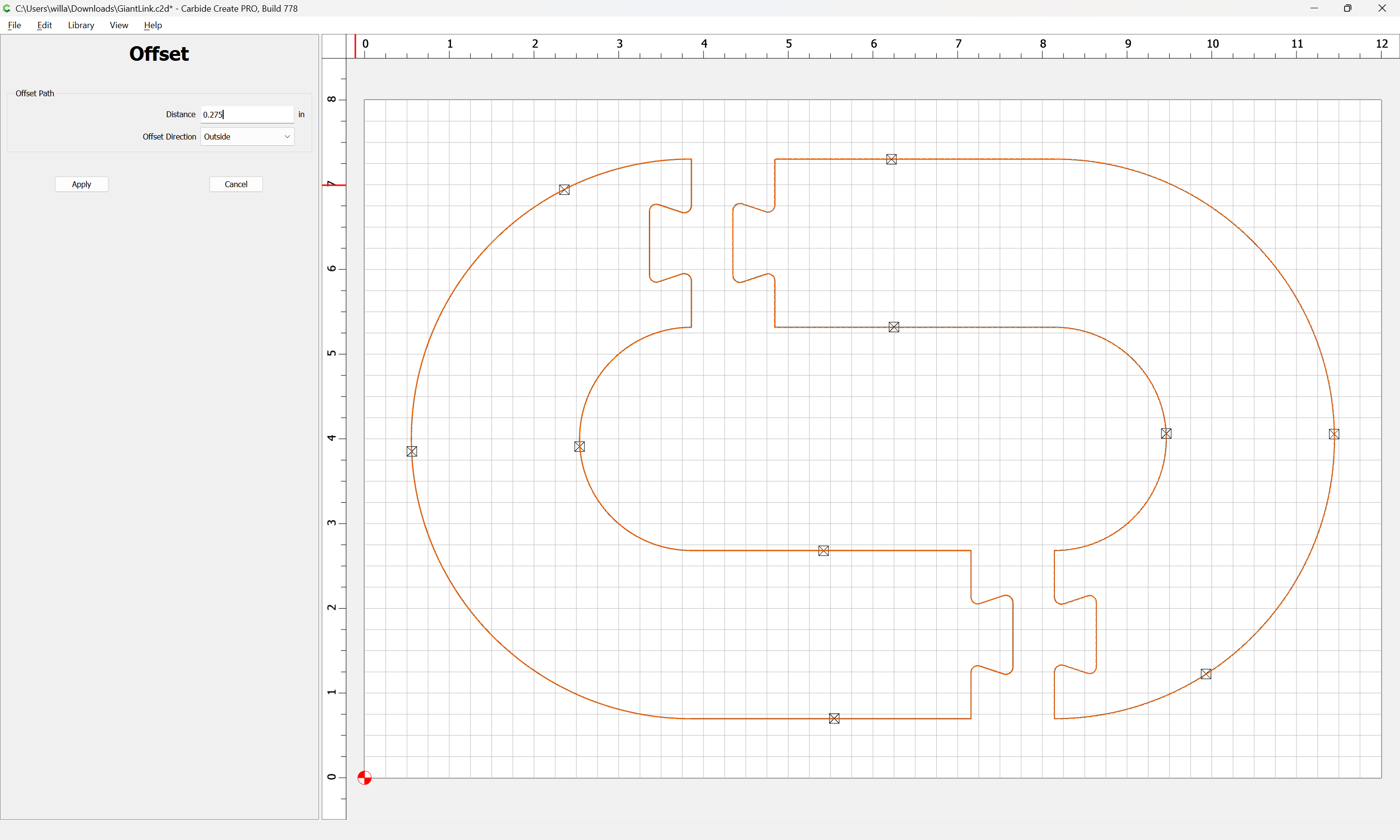
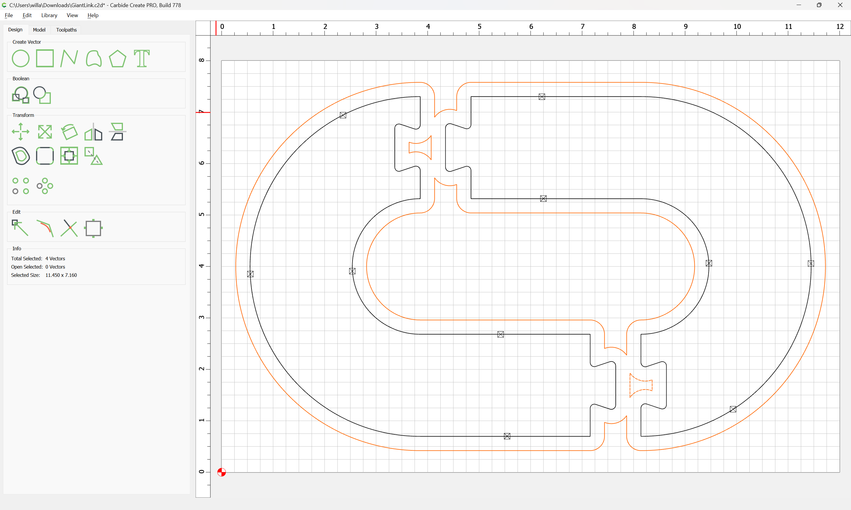
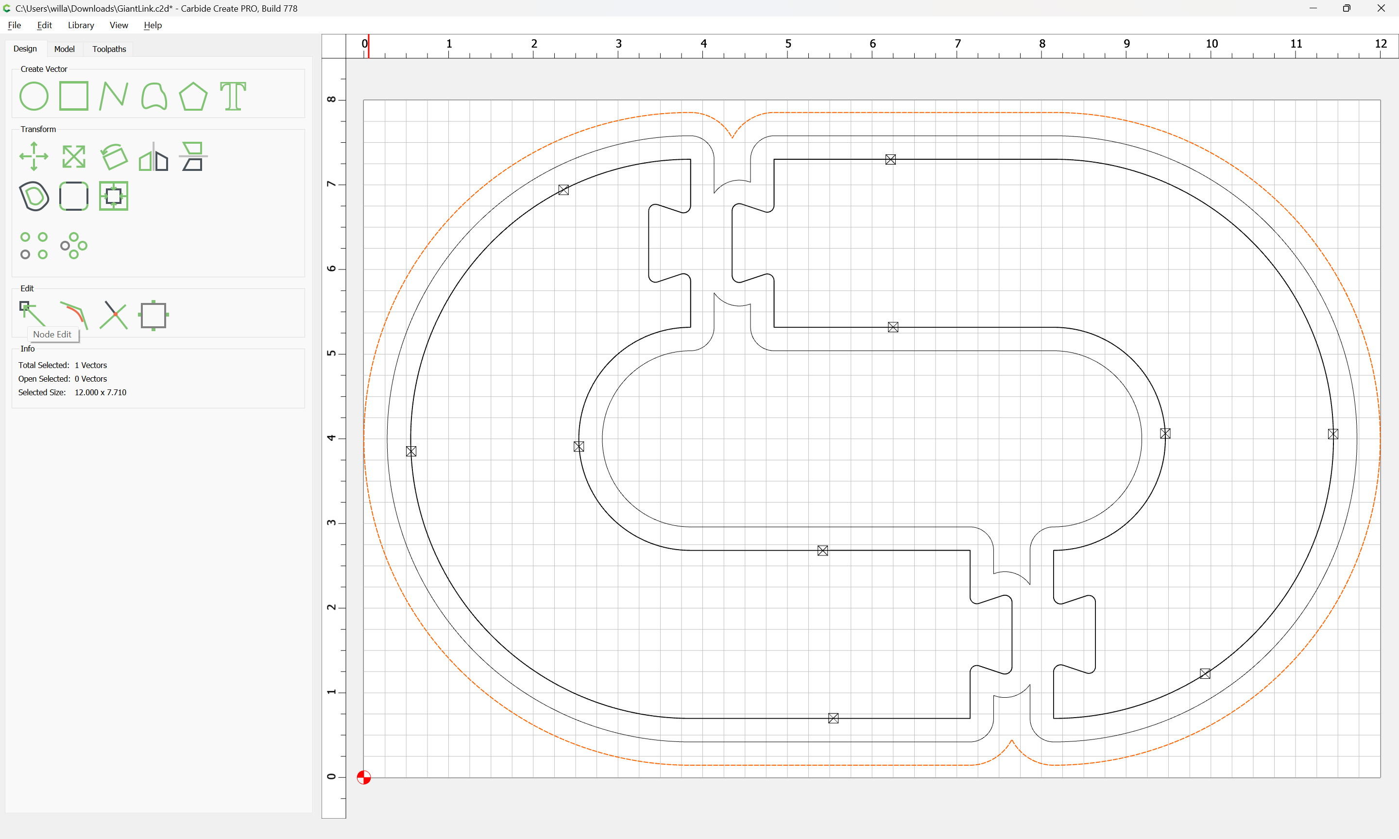
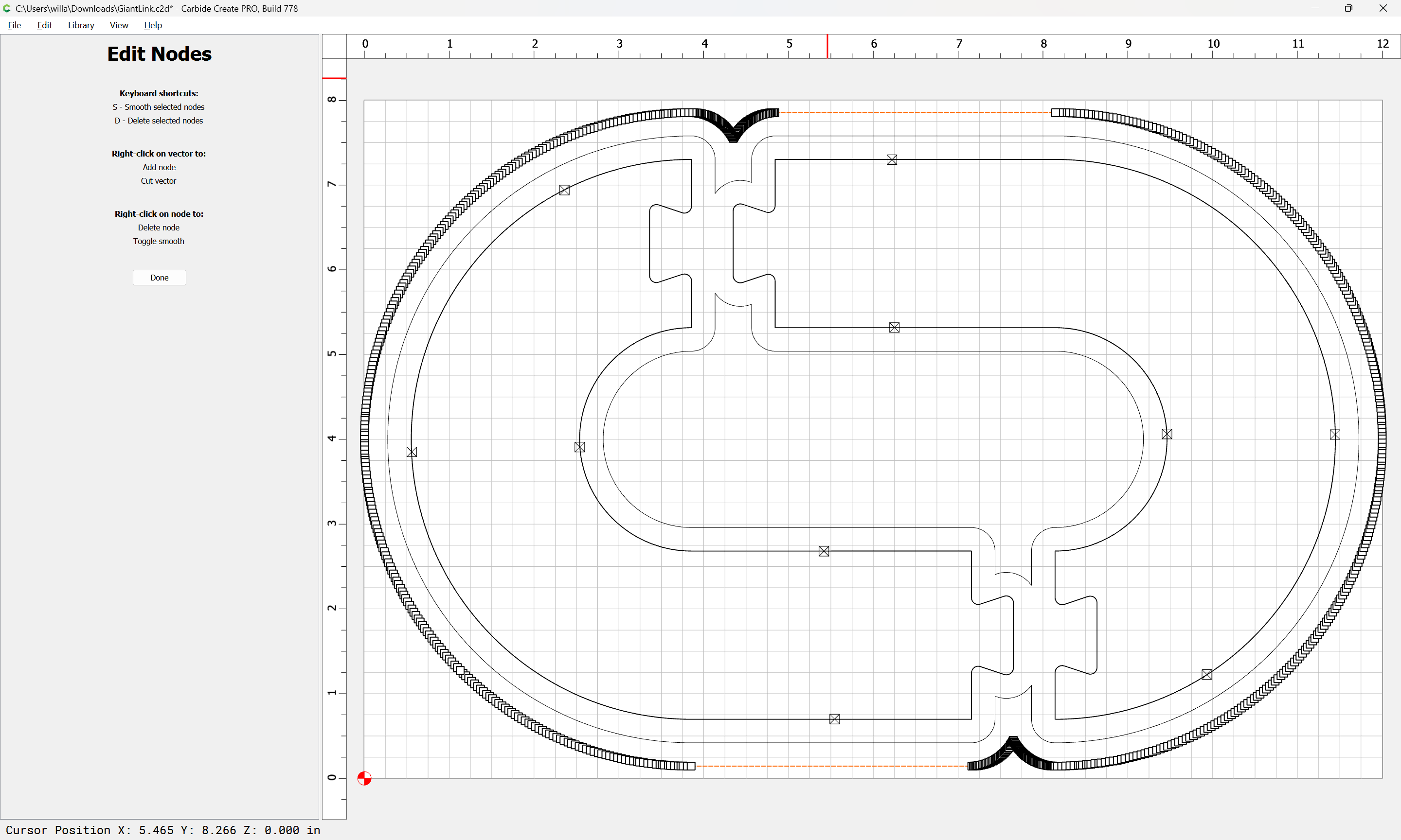
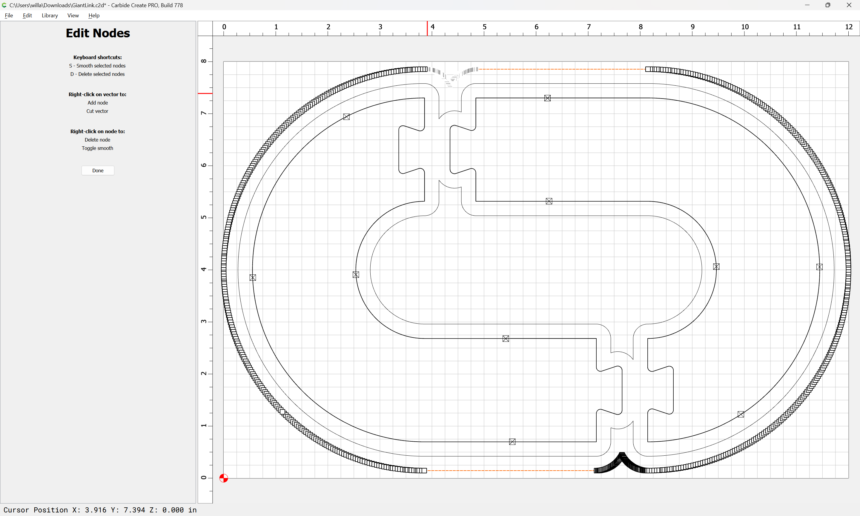
Then assign a Pocket toolpath using the smaller tool and enabling REST machining — to keep the algorithm from being confused it will be helpful to add further offset geometry:
… On the final contour path, use “Climb” instead of “Conventional”. If there is a bit of cutter deflection, climb cutting will push the tool away from the part, where conventional will pull the tool toward the part making it too small.
Ok after trying a bunch of different approaches, it occured to me to measure the width of the cut of one of the contours on my piece, it turns out to measure at 0.30 inches even though the bit is 0.25. I measured the bit and it is in fact 0.25 inches. I then did a test cut with the bit diameter set to 0.30 and the pieces fit togther perfectly.
So my next question is why would the cut width not be the same as the bit width. Its a pretty easy fix but I’d rather not have to do test cuts with any new bits to get the cut width and create custom tools for each one.
Well, after a full review of my entire setup, it looks like the router has an ever so slight wobble on the shaft, and thus the bit as well, resulting in the cut width at the tip being about 0.05 wider than the bit. I should have clued in sooner as the edge finish of my cuts had a shingle pattern with the cut sort of deeper at the bottom and angled, I chalked it up to cheap bits I used for projects with softer materials.
I did have a few crashes since i got the machine so perhaps one of them damaged the router. It hasn’t really caused any problems up until now as all my projects didn’t have tight tolerances so I guess I didn’t notice.
In any case, down the rabbit hole I went and ordered and HDZ - 80mm mount and a new spindle kit. In all honestly I have been eyeing a new spindle almost since I got the machine, mostly for a larger selection of tools and perhaps a faster cutting ( I seem to have alot of deep pockets in my projects, lol ) Of course this is going to spawn a whole set of different questions, but those are for another post.
Thanks to everyone who took the time to answer my question it was greatly appreciated.