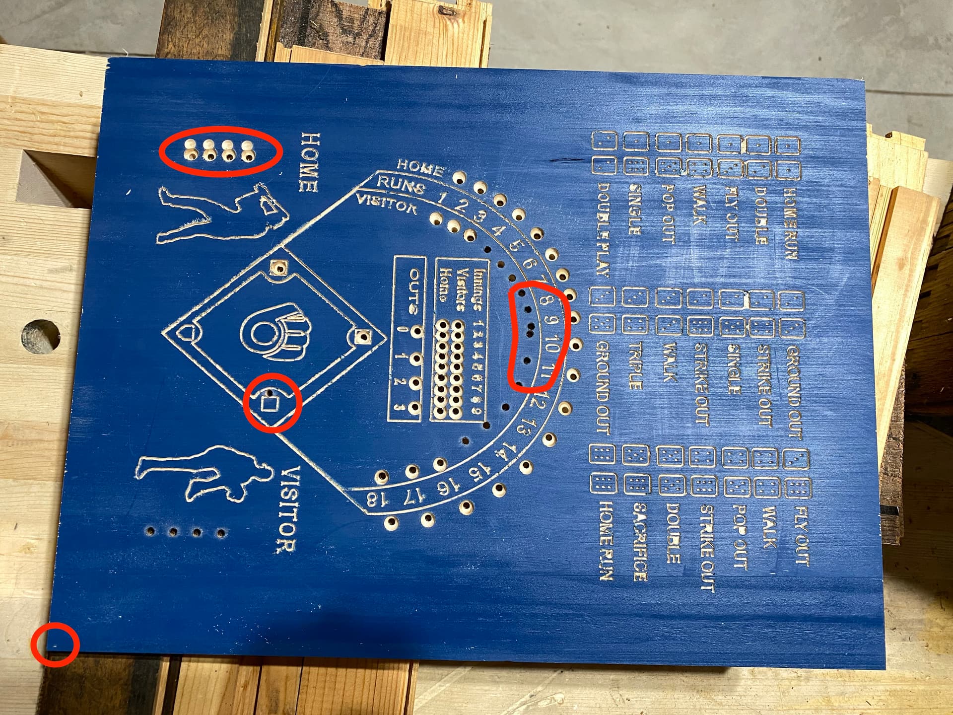
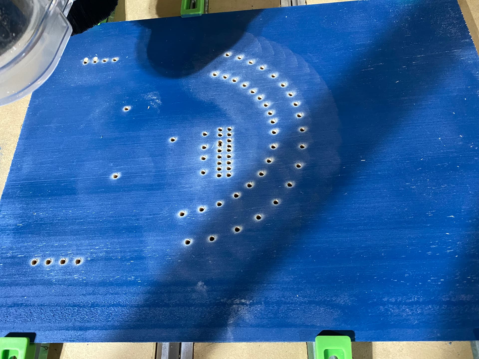
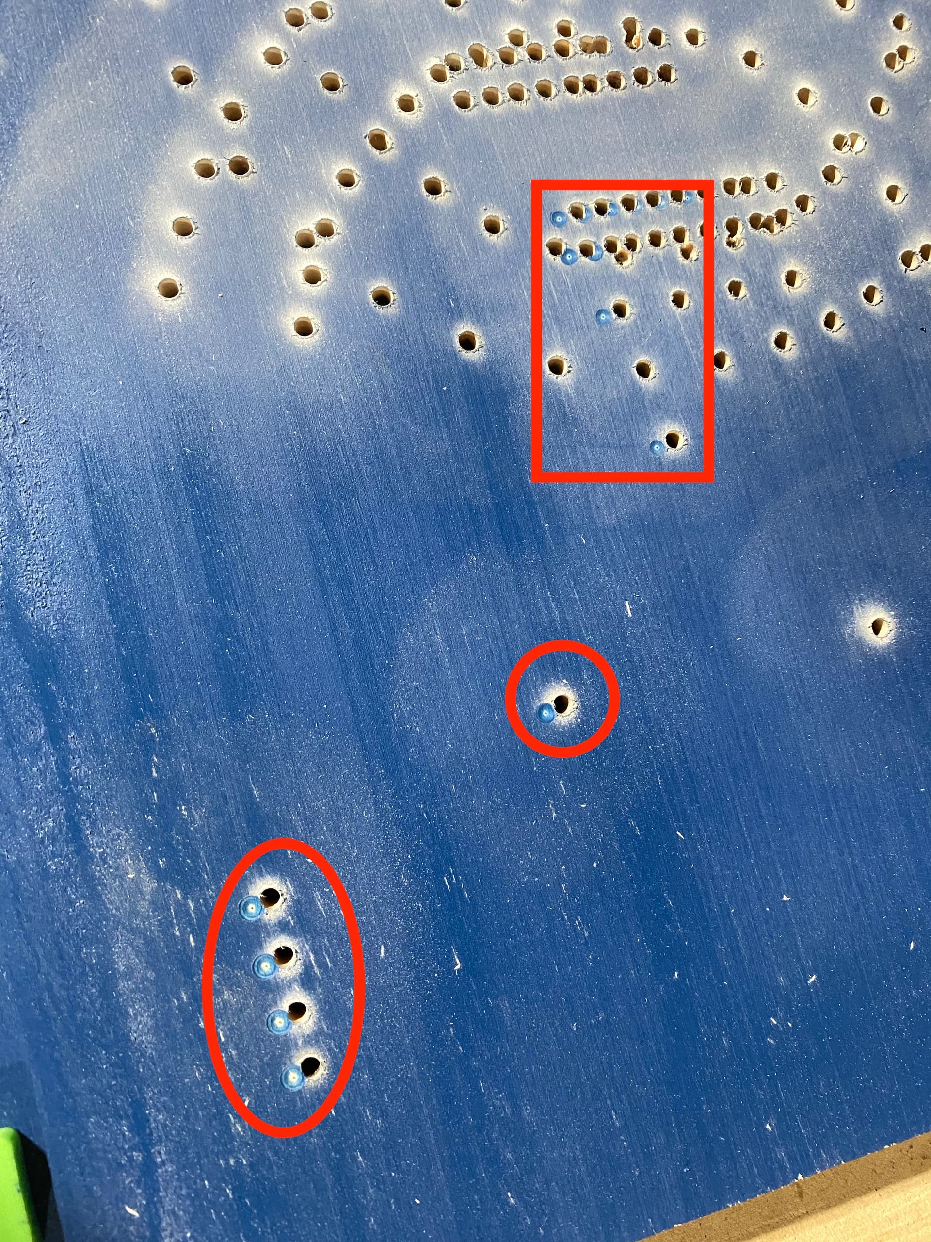
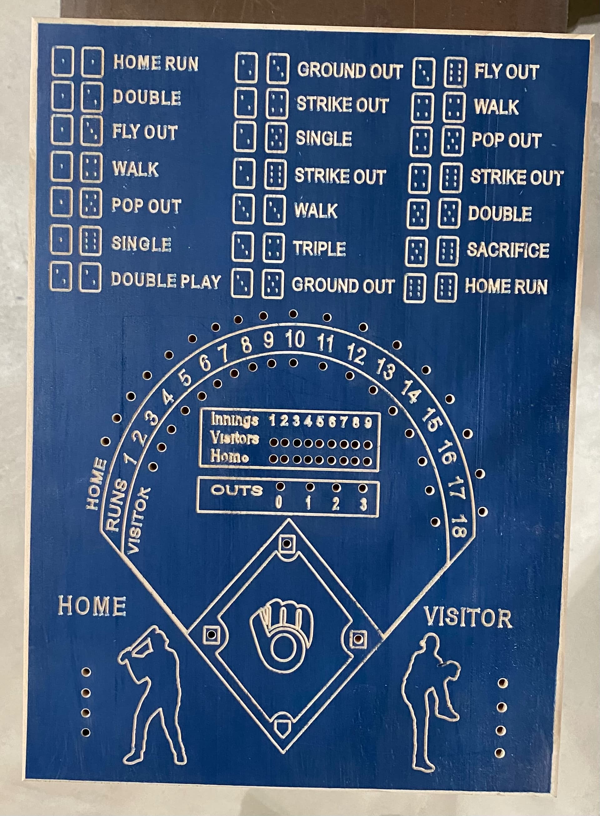
I have the Shapeoko 4XL that was put in use November 7th.Everything started off great and I was really enjoying the new piece of woodworking equipment. Then about 10 days ago I started having issues holding the Z zero. After reading some other forum chats, I took the machine back to the point of installing the V wheels and fine tuning the belt tightness. Some things did seem a little off so I was hoping that my issues were solved. The first project went pretty good and I was really happy. But now the X, Y & Z axis have a tendency to lose the zeros. Yesterday I was almost done with a project and after the last of only 3 tools was changed and ready to go, after clicking on the resume button, there was an unusual noise as the machine made its move. Sure enough, the Y & X axis’s were off. This project uses a 30 degree vee cutter, a tapered end mill for the peg holes and then a ball end mill to chamfer the peg holes. I don’t cut out the outline for this project, I trim it up on my table saw and use the shaper to finish the edges. Attached is a photo of my project with it being messed up. My hole chamfer is set for 0.020" deep and they went 0.190" deep. You can see where my the mistakes are, as they are marked in red. When I set the zeros prior to starting this job, I actually went a little deeper on the Z axis so I could use that mark in case I needed to rezero. This is marked on the lower left of the project. Any help would be greatly appreciated. I tried to upload my Carbide Create file, but I’m unable to because it is over 4MB.
Loss of zero usually happens when the stepper motors do not move when the controller tells them to. This can be caused by trying to force tools through material too deeply/quickly, running the CNC gantries to their mechanical limits, or vac hoses/power cables/etc resisting the movement too much.
Be sure to check the feel of your X/Y axis to make sure they feel consistent. Loose belts can also be a contributing factor, but you seemed to indicate you already checked those.
Another possibility is the set screws on the pulleys - if they are not tightened properly or were not oriented properly with the flat of the shaft, the motor shafts can up rotating without moving the pulley. Many users put a witness mark on their motor shafts/pulleys after checking/tightening them to give a future indicator.
Good luck!
Definitely ensure the set screws on the pulleys are tight and add witness marks. I am not sure that is the problem unless during homing, the pulley shifted back and then eventually slips the other way during cutting. The shift also looks abrupt in one direction and not happening in both directions throughout the cut. ( although the holes under 12 through 15 also look shifted).
I hate to ask alot of questions when someone is looking for help, but I am trying to piece together what happened from the picture:
- The v carve went reasonable with a little change in depth toward the bottom of the project based on the width of the lines (they appear wider at the bottom than the top).The machine homed when done.
- Switch to taper bit for the holes.
- Rezeroed by hand, x, y, and z. (or just Z?)
- Holes cut okay until the end and the last few shifted left in X? Machine homed.
- Switch to ball for chamfer. Rezero, x,y, and z. (or just Z?)
- Chamfers are a bit offset from the start but eventually shift to the left about the same shift seen in the holes.
Is this correct?
A few observations,
The four chamfers under “HOME” are cut twice. Did the tooth path do this or did you try again?
HOME and VISITOR look to be toolpaths for a different V bit (ie made for 60 but cut with a 30). This is based on the shape of the carved letters (tops and bottoms look like dog bones).
Overall, the cut quality is not what I would expect but that may be due to the size of the project (what is the height of your smallest letter?) and the material being used. Is this luan? With a 30 degree bit, in hardwood on a 3XXXL, I can get decent results down to about 3/16" or 1/8 " in height without much effort. Beyond that, I dont know.
If you want me to try to tweak the project, I can try it in Tigerply. But I dont have any taper bits and would just use an endmill/pocket for the holes. Can you export an svg and post it? I have some time off coming up and dont mind helping.
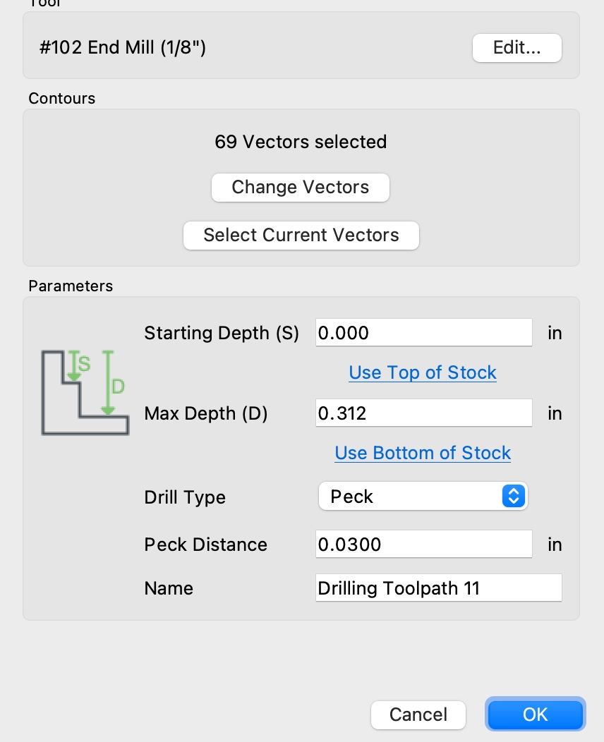
OK, this is getting bad!! I spent about 3 hours this morning going through absolutely everything. All six V wheels were all tight with slight pressure with the Y rails and gantry. Out of the three pulleys, two were lined up with the flat on the shaft. The other one was off so I fixed that. I checked the belts again and I can get one finger to about four inches from the end. On my first attempt today, I changed my tool paths so that I was drilling with a tapered end mill first (see setting on one of the uploaded photos). My second tool is a 1/4" ball end mill just to chamfer the drilled holes to a depth of 0.020". I stopped after the second chamfer because the Y axis is off. It’s not like I have not had any success with this machine. I have two photos from today and a couple of completed projects.
Some of those changes were after I rehomed (Zeroed). Under the single digit numbers, the holes are closer together than under the double digit numbers. I was using a ball end mill and I have a tapered end mill for the peg holes. And no, don’t be sorry for asking questions, I’m kind of new to this and I appreciate all suggestions.
Always check the machine per:
https://my.carbide3d.com/faq/machine-operating-checklist/
the basic points of adjustment for a machine are:
- (for belt drive machines) Pulley set screws — verify that these are in-place and secure — be sure to check all axes/pulleys (including Z on machines w/ belt-drive Z-axis, for an HDZ, check both coupler screws).
- (for the SO3/4, X- and Y-axes, and the belt-drive Z-axis on Launch and summer 2016 SO3s) V wheels / eccentric nuts (per assembly instructions)
- (for the Pro, Pro 5, HDM, and Z-Plus and HDZ Z-axis) Lubrication of the linear rails: CNC Machine Maintenance c.f., Making rail bearing lube easier - #9 by LiamN
- (for belt drive machines) Belt tension (see the relevant step in your instruction manual, Note that the X-axis motor is held in place on standoffs and if those bolts are loose this can cause belt tension issues. Also, belt tension for the Y-axis stepper motors needs to be even/equivalent on each side — a significant difference can cause skipping on one side eventually resulting in lost steps on both. Measuring belt tension, squaring and calibration
Naturally, this assumes that all the wiring is in good condition and all connectors secure per the Machine Operating Checklist. Verify that all wiring is in good condition and all connectors are secure, and that all wiring leading into connectors are properly in place and are secured so that the wiring leading into and away from connectors will not shift.
A good video overview on setup:

Tramming the Z-Plus: https://youtu.be/rGOGlNurglE
Ensure that all screws are in place and secure, esp. on the linear rails on a Pro.
The big thing to remember is that while the machines are conceptually complex in terms of the number of parts multiplied by the axes and their interactions, the basics of motion are quite simple:
- the CAM software creates a G-code to move the machine
- a file containing that G-code command is sent to the machine over the USB cable and interpreted by Grbl
- the controller then has the stepper driver chips send signals over the wiring to the motor(s) causing them to turn
- the motor shaft then causes either a pulley to rotate, or the lead/ballscrew to turn
- the pulley or screw then interacts with a belt or nut causing motion
- the motion is guided along an axis by linear rails, which either have a V wheel (positioned by eccentric nuts) or linear blocks w/ bearings
Check each aspect of the machine — on a belt-drive machine it’s almost always belt tension, or eccentric nuts/V-wheels, or pulley set screws…

Will this do?
Yes. Size is ~8.5 x 13.5 with the smallest letters about 1/4 inch high. What is the most telling is the number and quality of your successes. All easy causes are ruled out because you clearly know what you are doing.
Looking at todays failure where you did holes first then chamfers: it looks like one or two holes also shifted but in the opposite direction from the chamfers. If so, to me this still suggests one of the Y pulleys is slipping on its shaft. If the holes are okay and only the chamfers are off, then maybe homing/zeroing is not reproducible in Y.
Another way to check the pulleys/shafts is to stress test them. Mark them, load the svg below, and air cut as a contour with a very fast feed rate ( no router needed in your case because if slipping is happening it is not due to lateral cutting forces). While running this, observe the pulleys/shafts watching for slipping as Y changes direction.
I have a belt driven Shapeoko 3 and never fuss with belt tension. Mine are ‘generally snug’ but far from tight and almost guaranteed not the same tension on both Y belts. For projects in wood it is no problem but I dont push the machine or care about high precision. I do recall someone who installed the belts incorrectly in the retainers and had trouble maintaining tension. If your belts seem to loosen frequently, It might be worth posting a picture of how they are in the retainer clip things.
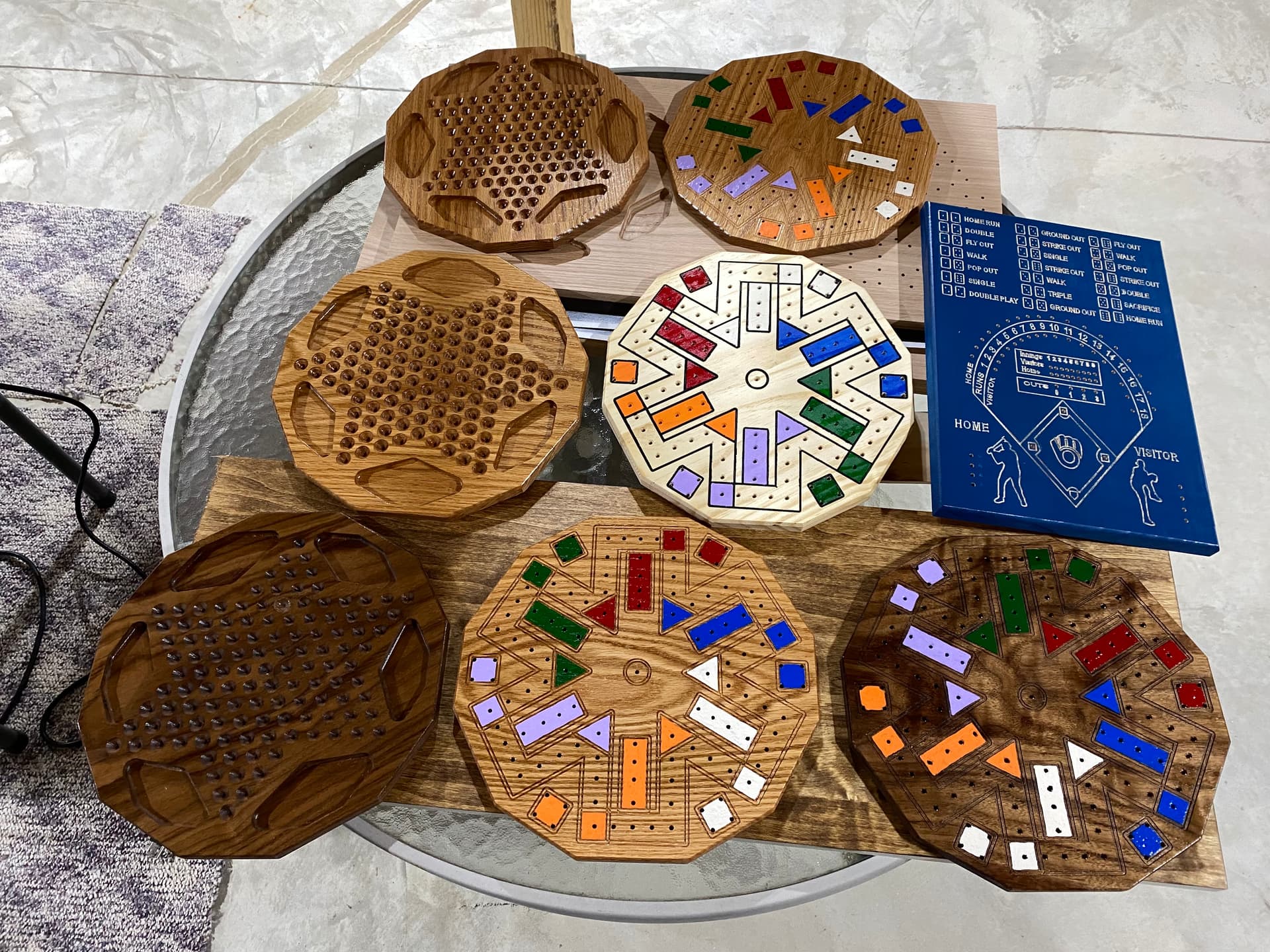
I cant even help much with your file, it is in pretty good shape. Your completed baseball game carved pretty nice.

Thanks Bozo, I appreciate your kind words. Yes, I feel that I have the confidence to get this mastered. As far as the belts being installed correctly, when they pass through the clips, the ribbed sides face each other. They really are not losing up. I’m a retired CNC machine operator, but we didn’t write the Fanuc code. Is all we could do was make minor edits and they were never saved, only engineering could do that. I have sent an email to Carbide 3D and hopefully I will have some more communication tomorrow. I’m at a point now that I’m wasting my time and material until I can get some other experts involved. The only thing is that I’m doing these now for Christmas gifts. Have a great night.
I think Will mentioned wiring. Maybe an intermittent bad connection/short in the wires going to the Y steppers, affecting them both at the same time. Not something I have experience with. I suppose you could have it travel Y, while moving wires/connectors looking for hesitation in travel.
I have had this happen on my SPROXXL.
Could not figure out what was causing my X-axis to stall/miss steps. Then I realized that my vac hose was brushing against the X-motor connector to the wiring harness randomly. After I got the connector secured safely under a bracket, have not had that problem recur.
So definitely worth checking that all cable connectors are secure & do not get strained in any way while the gantry moves around.
It may also be a good idea to give each conductor a tug on the connectors - a poorly crimped pin can work sometimes but then fail intermittently. I’ve had a couple of those too.
Wiring was mentioned. I am not a big fan of the connectors used. My “Z” kept having issues. Replaced the harness, happened again. Went with this.
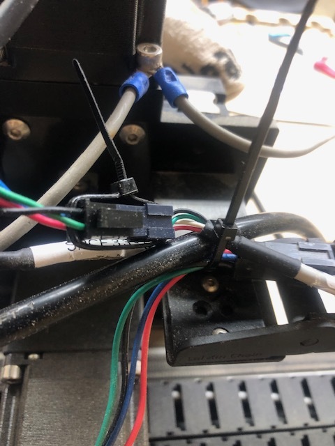
Yes I have removed the AC cord from the harness
Thanks guys, I’ll check some more things out today and use a scrap piece to see if anything has worked.
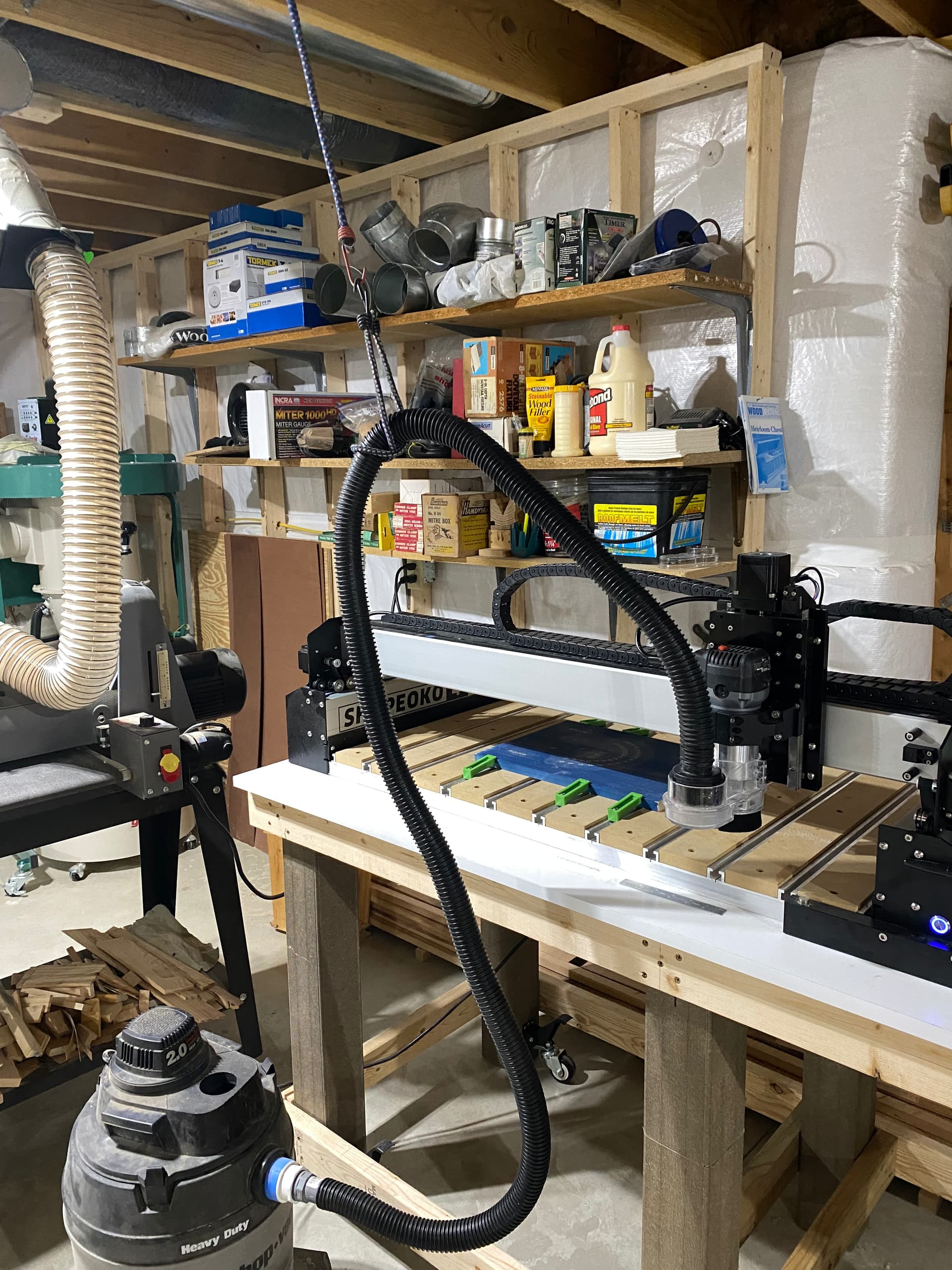
Ok guys, after going through all of the electronic connections and zip tying them closed, I still am having issues. I did not remove my project from yesterday, but flipped it 180 degrees, that is why it’s such a mess in the center area. I’m tired of wasting wood unnecessarily. Here is a photo of how I have my vacuum set-up to the Shapeoko 4XL with bungee cords, it moves freely and doesn’t catch on the table edge.
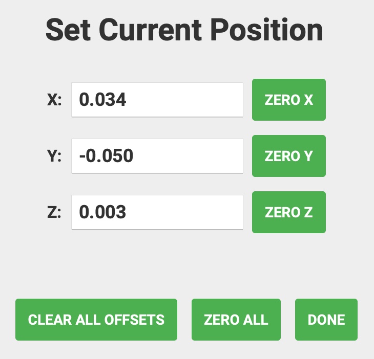
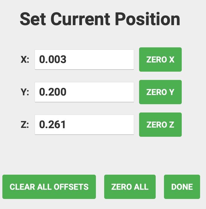
In this photo is how much my zeros changed after chamfering yesterday.
In this photo, you will see my attempt to chamfer some of the peg holes today. The little white spots are the chamfers.
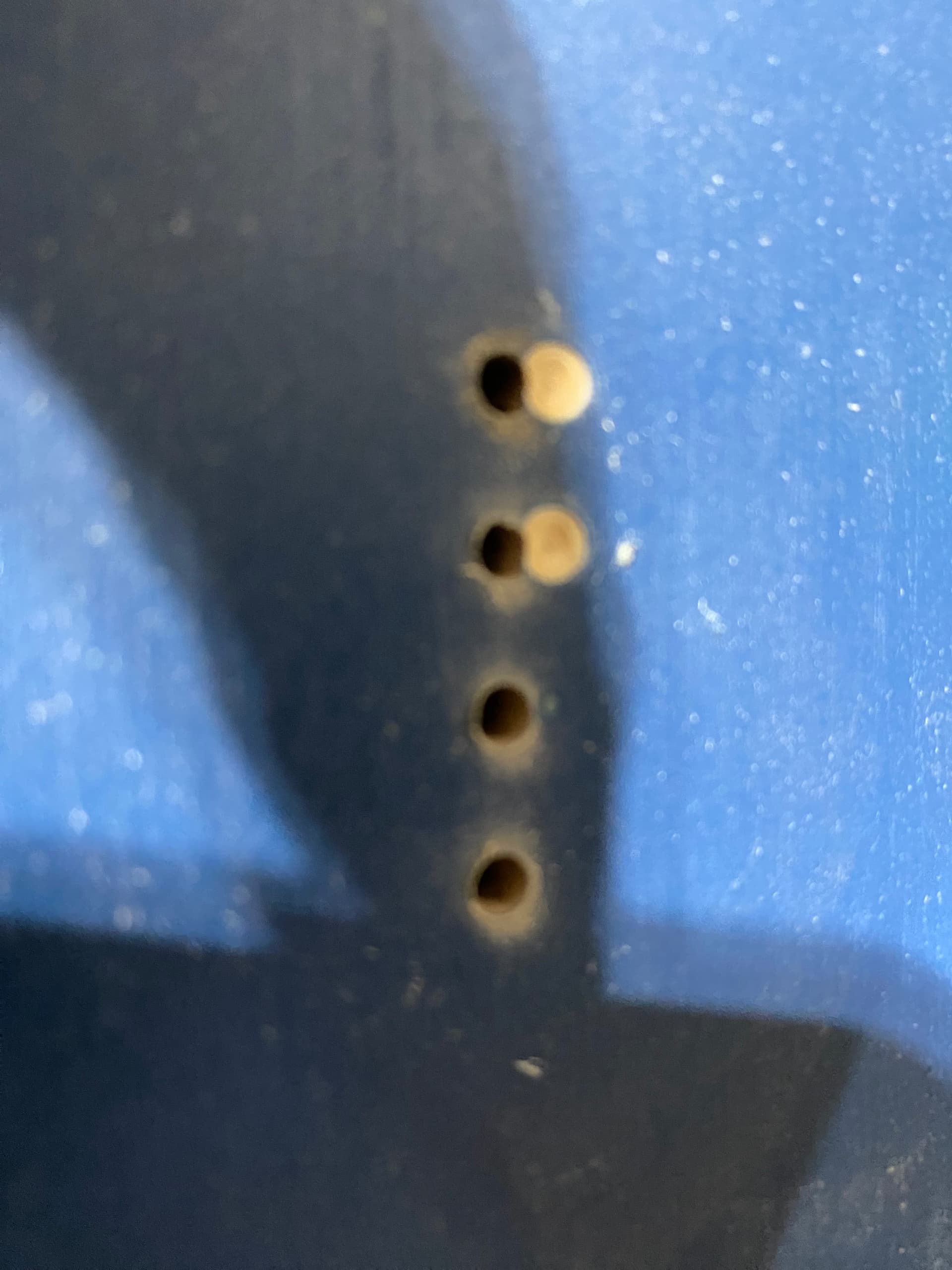
In this next photo you will see how much my zero’s moved. After setting my zeros initially, I move the Z axis into the wood to make an indentation so that I can check it later. I’m using a tapered 1/16" end mill for zeroing.
I have an email in to Carbide 3D support, hopefully they can help me out.
Are you using inches or mm in CM? I’m assuming inches because otherwise those values would not cause nearly as much offset.
As you seem to have gone thoroughly over your machine, the only other thing I can think of to do would be to slap a scrap piece of whatever on the bed & try cutting a simple calibration square/circle which can be measured with calipers.
Also, just jogging the machine around manually to see if the offset appears - set a zero point, jog the gantry around the bed listening/watching for anything that doesn’t sound/look smooth, then tell it to go back to Zero.
My inclination has me thinking it may be your belt tensions - though you did say you checked that. But what about the ribs on the belts? Do any look like they’ve been worn/chewed down? Doesn’t seem likely, but never hurts to check.
I’m a fan of setting my belt tensions via spacing a couple 1/4" bits 18-20" apart under the belt & pluckng them to see what frequency they vibrate at with a tuning app. Helps me know when the belts have stretched & need tightening or replacing.
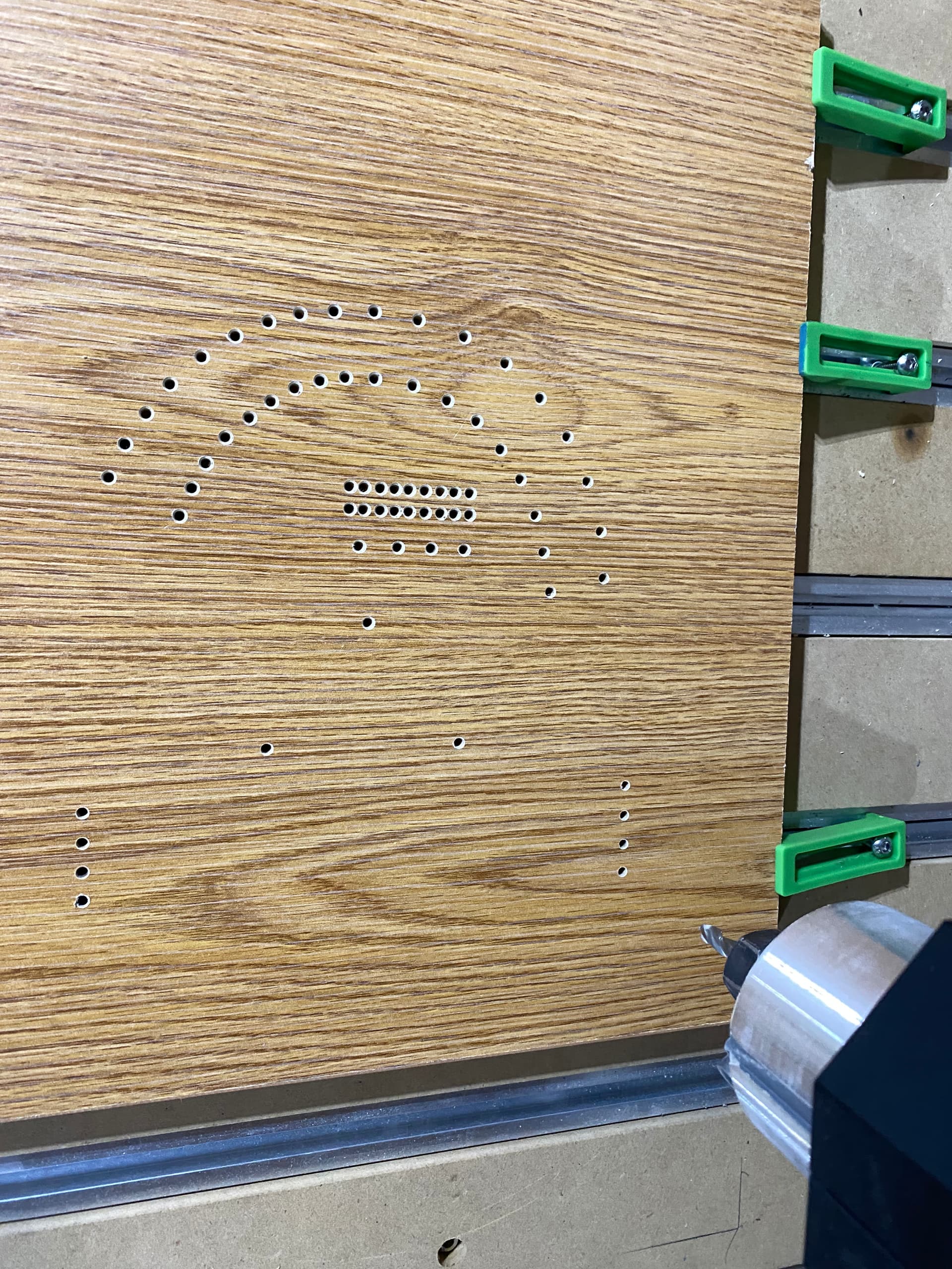
Ok guys, I think that I have it. As it turns out, it was the belt tension(hopefully it’s gone). According to one of Carbide 3D videos on setting up my Shapeoko, they recommend the tension as being able to get a finger under the belt and being about 4-6" away from the end. I was just over 4" from the ends. During all this time, whenever I would “Jog” the machine everything sounded good. Well, I did some rapid movements and it sounded terrible and the gantry was not moving evenly. So I started adjusting the belts again and now they seem loose to me as I can get my finger to about 2" from the ends. I proceeded to make several movements all over the place and everything sounded great. So I threw on a piece of particle board and did my drilling and chamfering. The chamfers appear to be centered with the peg holes. The photo shows some variation in the depths, but I think that is from the board probably not being flat. Also, the photo is at an angle so it may not appear exactly right, I’m good with that part. I can’t stress the gratitude enough about all the help everyone was throwing my way. Sometimes I interpret things in the way that is good from the sender, but when it gets to me, I mess it up. Thanks much everyone for all of your time and help. Have a Merry Christmas and happy cutting.
On an unrelated subject, but to possibly prevent further headaches, The screws for your hold down clamps should be placed close to your material. Think of the screw as a fulcrum for a lever. All of the clamping force provided by the screw is being exerted on the table, and not your work.
Good to see the chamfers now are lining up and this is definitely usable but the machine can do much better with respect to the letters. I have nearly redrawn the entire board and believe it can be cut with one v bit with the exception of the peg holes. Unfortunately, I am saddled with home work for the next two days (at least) and you will probably be done with your gifts by the time I can be of much help.
I was also thinking maybe add some beer cans and hot dogs to the board, of course for the grandkids. ![]()
I carved a version of this a while back and put a pocket in to hold the dice. That was a nice addition to try and keep things more or less organized.
I didn’t have a good color contrast like yours so I may remake it.