Sorry it’s taken me this long to write back. I got one previous post replied to then I haven’t had even 5 minute gaps between having to deal with something. That also might make this more disjointed than usual as it’s written 2 or 3 minutes at a time over 3-4 hours.
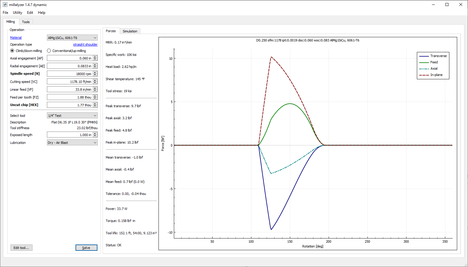
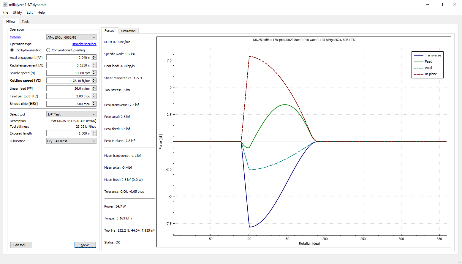
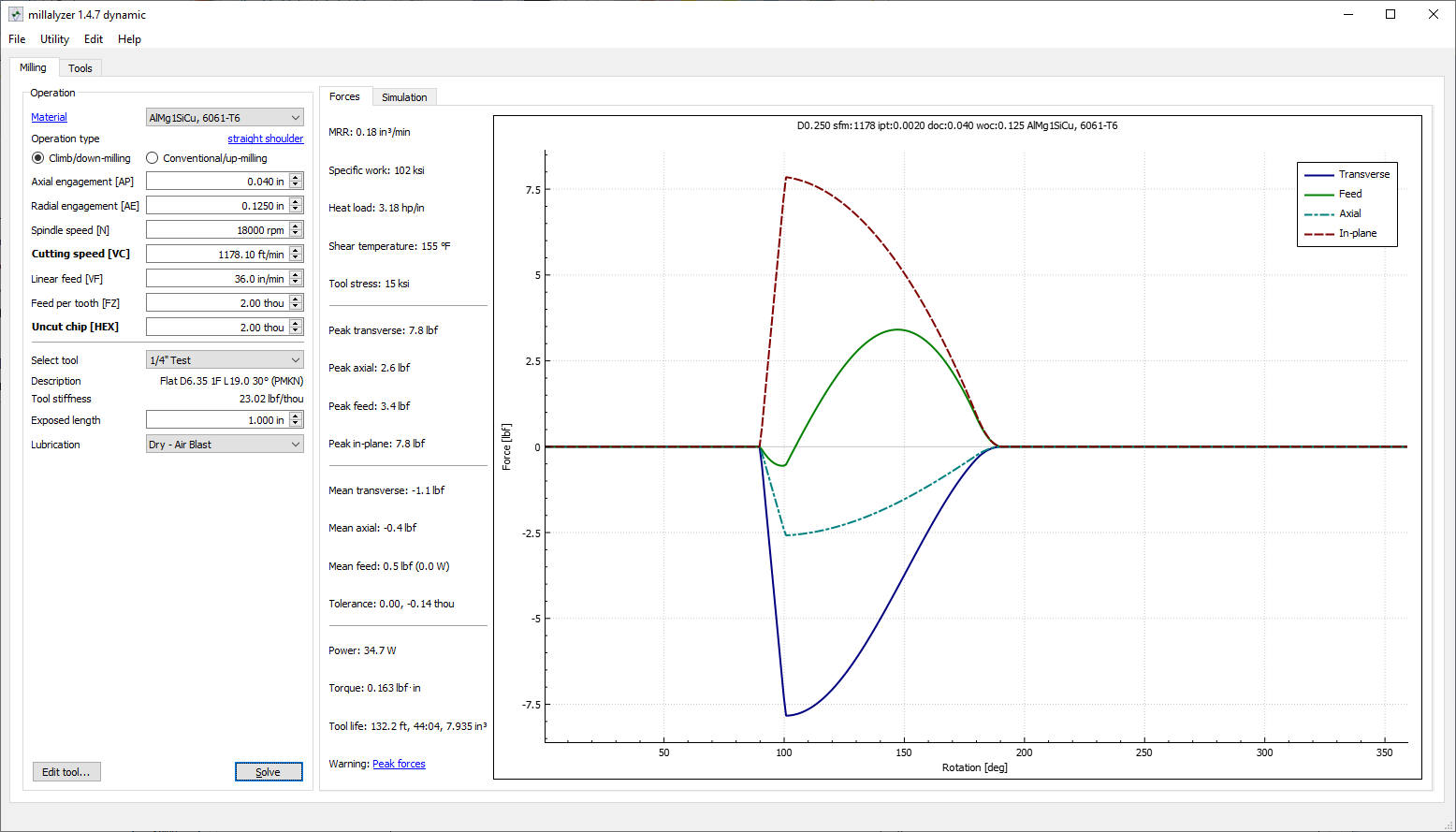
So I ran some numbers in millalyzer (it’s the easiest to setup for this). While it’s far from perfect it does give some good numbers for what’s going on in the cut. I used as much data for the tool as you have in the HSM numbers. Don’t know rake so I went with 20°. That will change the forces but it’s shouldn’t be enough to render the data worthless. I’m going to call the previous one with 0.060" DOC, 0.0833 WOC, and 0.00188" chipload dataset 1. Dataset 2 will be 0.040" DOC, 0.125" WOC, and 0.002" chipload. Common to both 18KRPM, 1" stickout, 0.75" flute length, 0 radius, 0.25" diameter. Here’s the results:
Dataset 1:
Dataset 2:
Dataset 1 has higher peak forces but less overall time in cut per flute per rev. It’s a combination of chipload and stepover. I think regardless you are at the edge even with the previous cut or something else is changing.
In theory dataset 2 while requiring more torque should be a better cut. It has less peak forces and smoother engagements. But that means that the steppers and spindle are working harder and/or longer at peak load potentially causing the issues.
Changing millalyzer to the “desktop cnc”, which my understand is, based on the nomad (another reason I’m using it for this). Then changing the spindle power and max RPM for the new spindle I now get these numbers.
Dataset 1 Desktop:
Dataset 2 Desktop:
The things to note here are the tolerance is about triple and the “peak forces” warning for both. I don’t know how good this model is for the nomad but it’s saying both cuts are at the edge or over the peak/mean force limits for the machine and causing at least some deflection.
So there’s other things not taken into account here. The first is again the deflection. Since you are climb cutting the deflection is pushing the cutter away from the material. This means that whatever your deflection is gets added back to WOC in the next cut.
I don’t mean to be depressing, especially after you have just made a big upgrade. But the short version here is that you are running up against the limits of your motion system and I would bet deflection (machine rigidity). Forces are functionally cubic material removed per flute per rev. Although tool geometry can change the force amount and direction of those forces. So I would look at reducing either the pass depth, tool diameter, or chipload. My personal choice would be tool diameter.
Then I’d use this method. Start off at an absurdly low DOC. Something like 0.005-0.010". This will help to minimize any deflection and force limits. Then run passes at different chiploads to find where you get a decent/good cut. I don’t know that tool geometry well enough to give great numbers on that but don’t start at less than 0.001" chipload. Probably the best cut for the mill is going to be over 0.002" chipload. After you find that number use it and start running test passes incrementing the DOC. You should reach a point where you realize that you are exceeding a maximum (e.g. skipped steps, large change in volume, poor cut quality, etc). Stop there and then back off 5-10% to give give yourself some margin for things like tool dulling. Alternatively, you can use this data as a base line for forces to use in a chip thinned adaptive if that’s your preference.
I have more that I’d like to expand on with this so if I can I’ll come back later and fill out some things. But going to post this for now. Let me know if there’s something specific you want me to address or that I can help with.