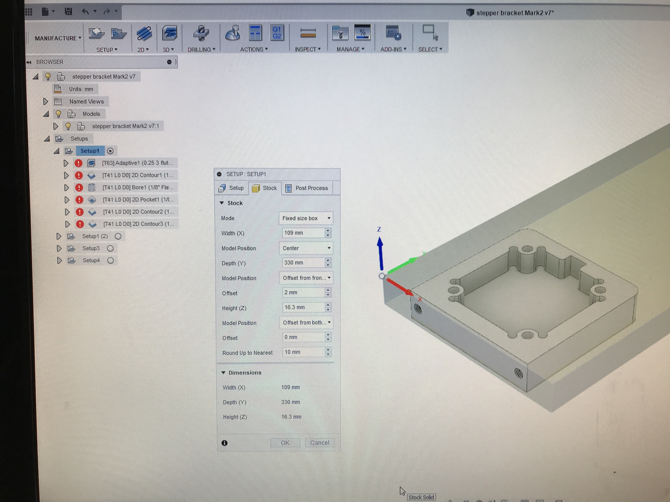
You could do the same cut without the 10mm offset in the Geometry tab, I just discovered, but I wonder if you’d get more heat in the narrow channel being cut? I’ll see what happens if I cut the part again.
Yes, it is similar to stepover. OL will maintain a constant DOC.
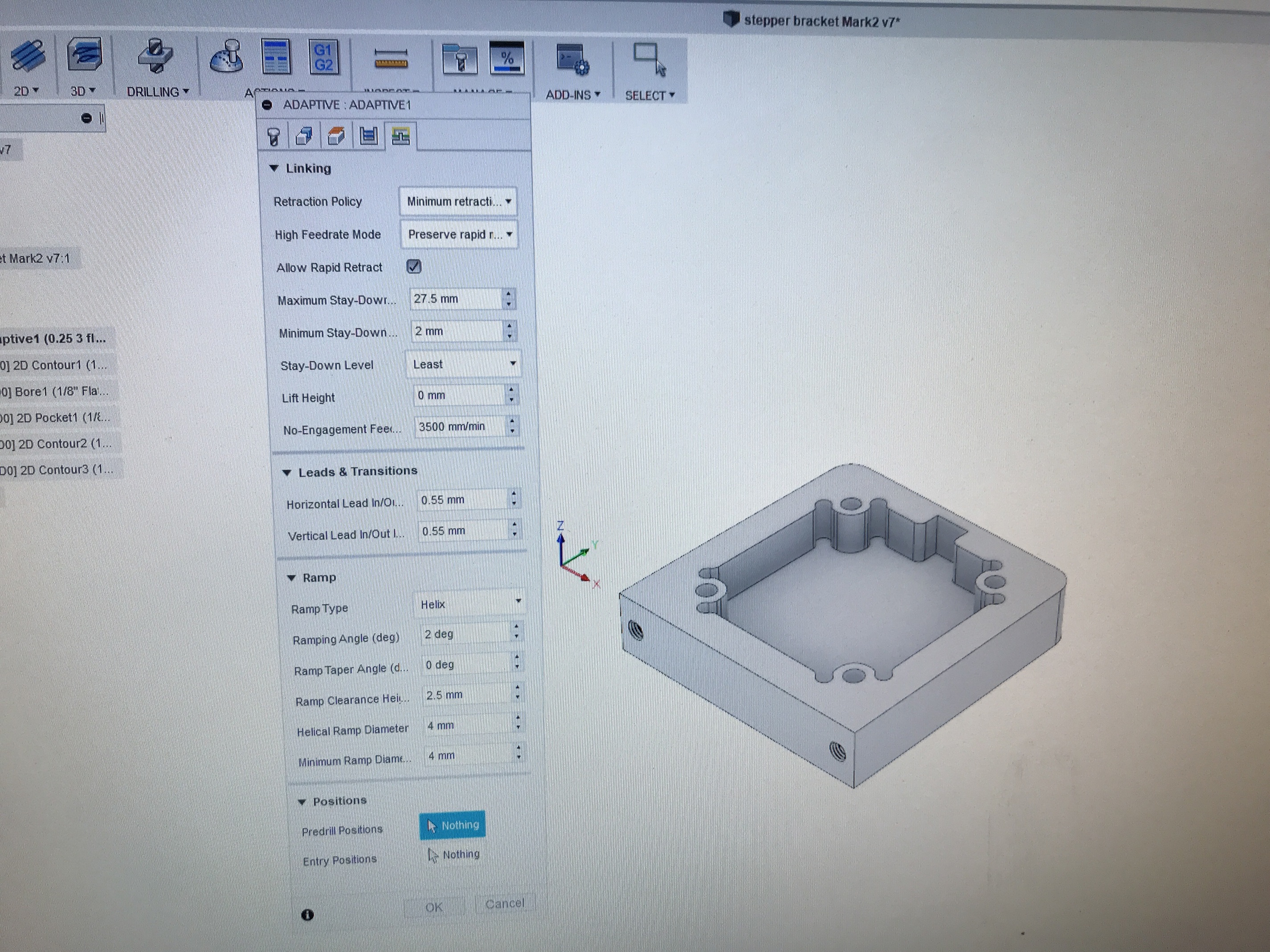
For choosing where it enters, you need to go the rightmost tab in the toolpath setup “Linking”. You can tell it to not enter from the edge there down at the bottom.
Otherwise, you may need to go to the “Geometry” tab and force it to stay inside your boundary and not to try using all your stock.
Yeah, I’ve tried setting the entry point on the linking, but it doesn’t seem to let me select a spot in the middle of a geometry plane, I can only select edges.
Tried attaching my file here, but it won’t let me attach .step files. Guess this will have to wait until I get home tonight.
I’m sure I’m missing something obvious…
@griff, thanks for the pics.
I’m not seeing an entry point setting in there. So I guess that bore operation was the start of the center pocket?
Griff
(Well crap, my hypometric precursor device is blown…)
331
Honestly, I’ve never set an entry point.
In this case the entry point was the lower, right corner.
Griff
(Well crap, my hypometric precursor device is blown…)
332
Just add .zip to the end of the file and tell the recipient to remove .zip.
thanks griff. can’t believe I forgot the extension trick.
suppose i could just zip it too. didn’t see that in the list the first time around.
anyway, here it is.
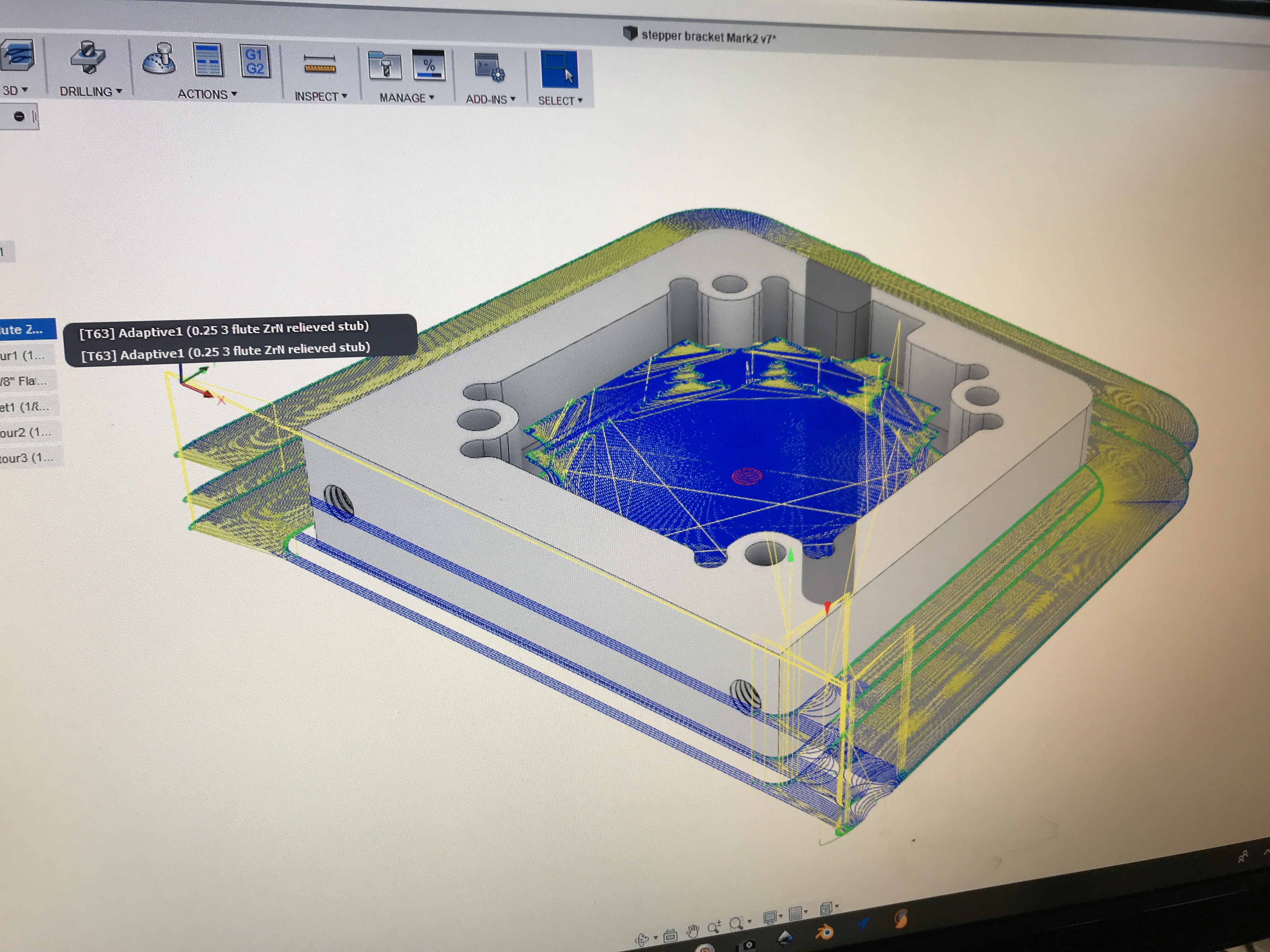
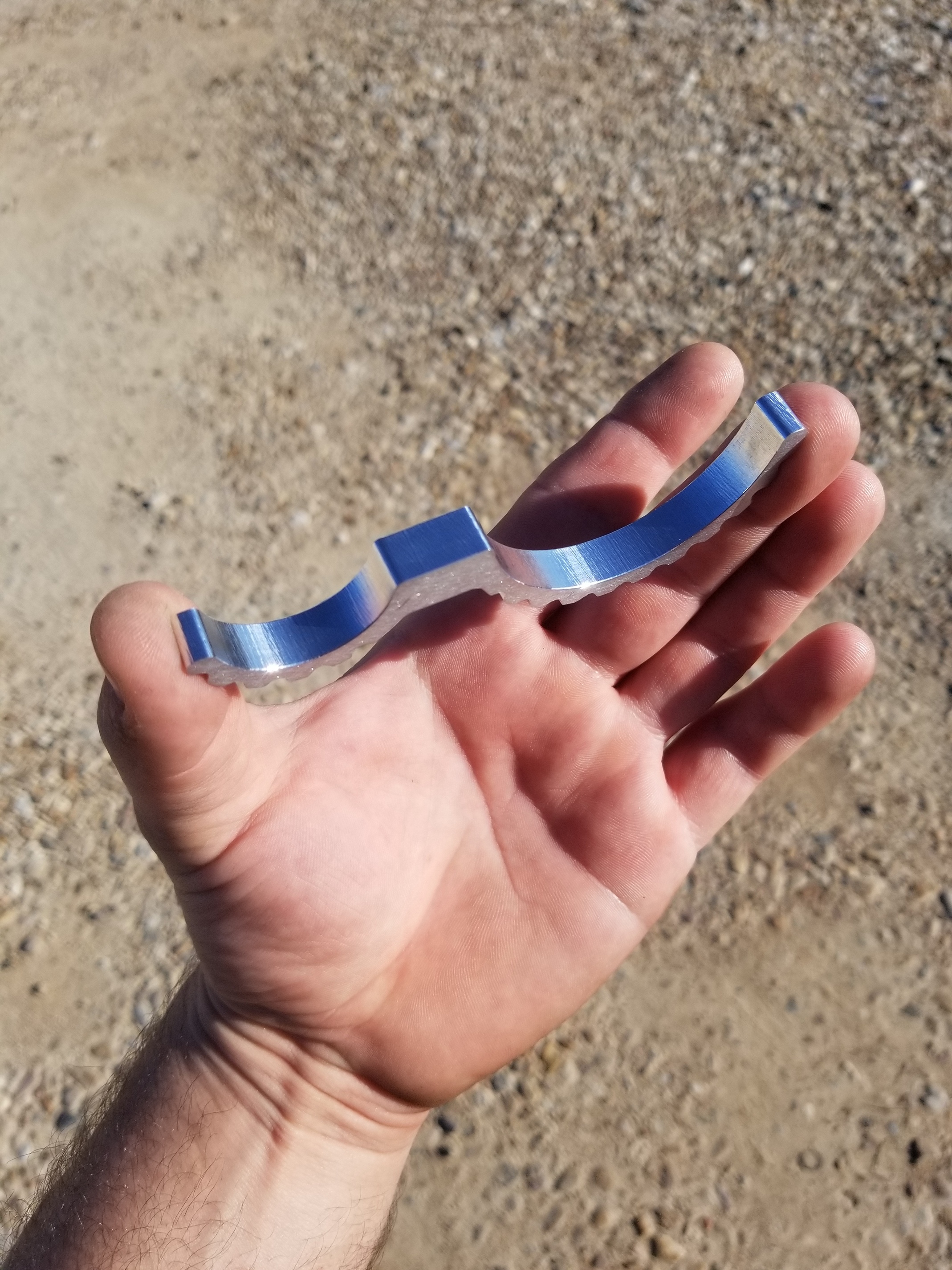
it’s just a small touchprobe plate, but the stock is bigger than the piece (may not be reflected in the current design… i’ve been mucking around a bit). So the start of the pocket when set to adaptive is a full width/depth gouge around the outside that’s more than the router likes to handle.(current path is standard 2d pocket because I couldn’t get the optimal the way i wanted)
Just for anyone else’s interest, the file extension is “.step” not “.f3d”.
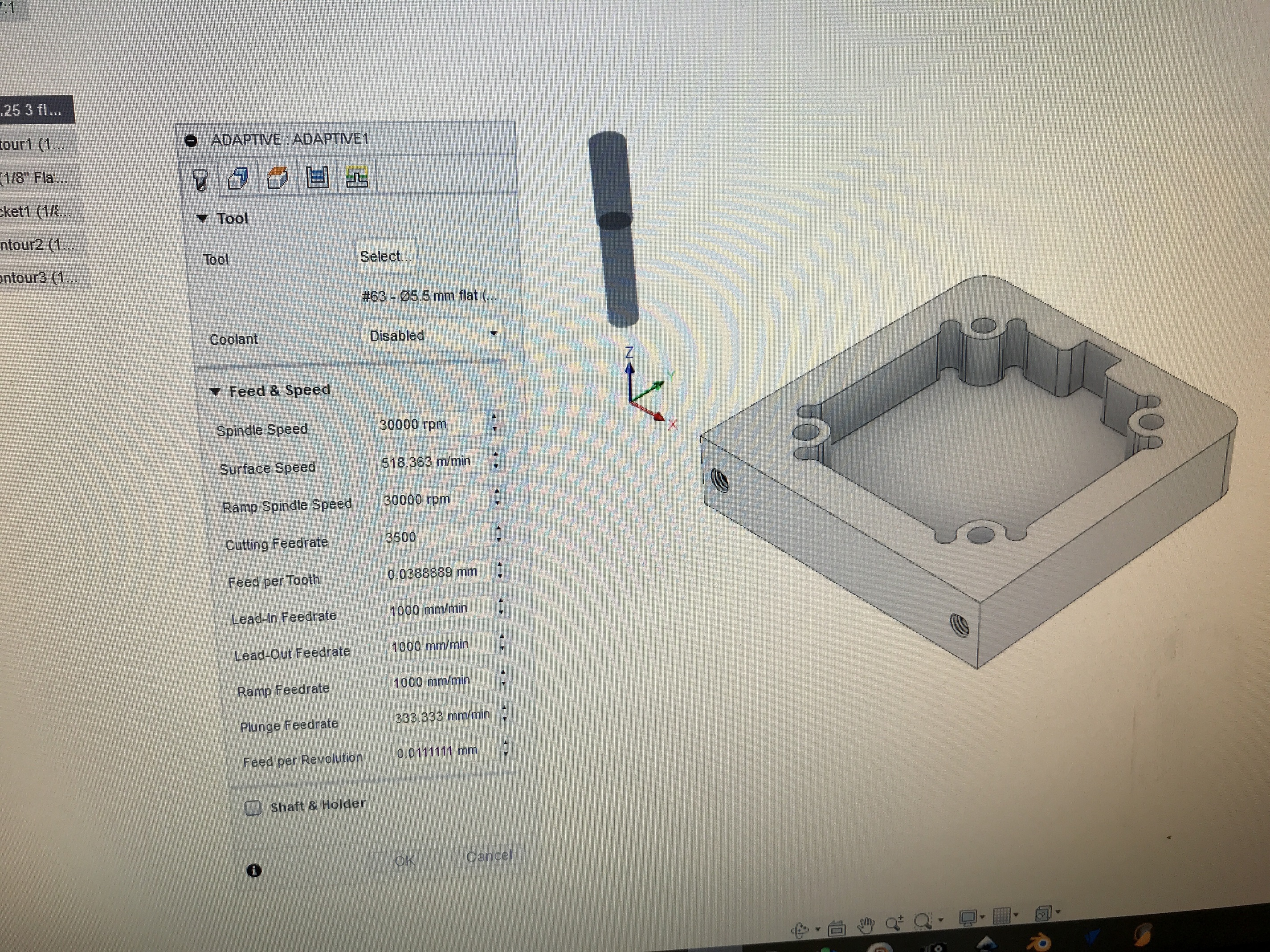
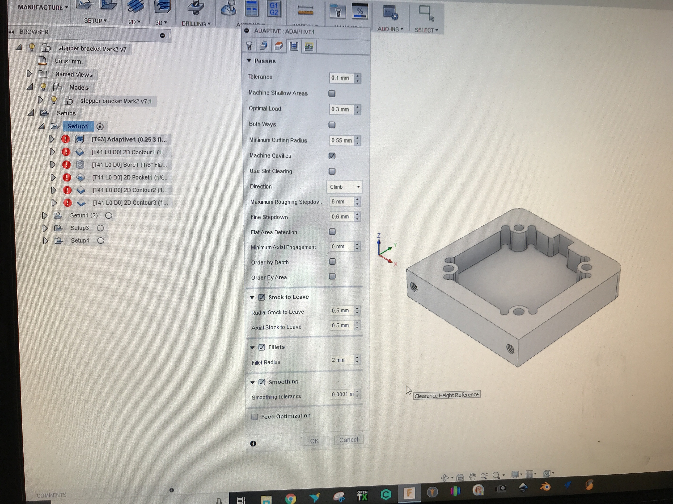
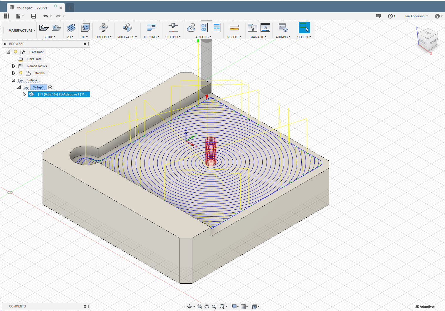
I tried it out and generated an adaptive clear for the recessed bottom portion. It enters in the middle with a helix like I expected it to. However, my setup stock is set to exactly the same size but doesn’t alter the tool path when I increase the stock setup. Otherwise, the rest of the setup are the defaults.
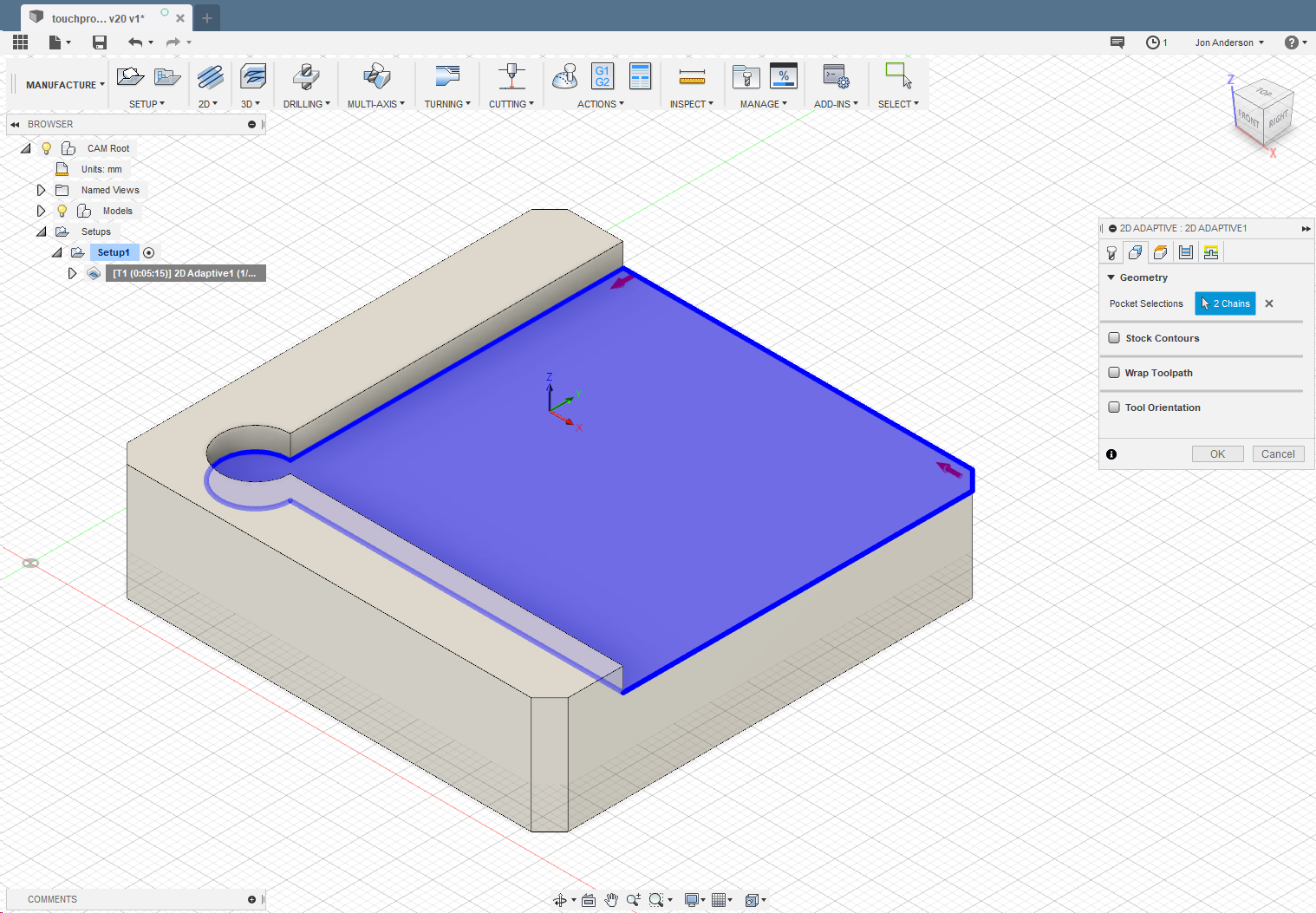
Oh, I did get it to try and enter outside the stock but it only happens when you select the face and not the 2d contours. As a general recommendation I heard, when using 2D toolpaths, try and select the contour lines as much as possible to avoid scenarios like this.
If you want to select the face, you will be better off switching to 3D adaptive, then everything worked like the 2D adaptive when I selected the contour lines.
Happy to report that I finally got the adaptive toolpath working.
Seems i missed those little red contour arrows the first time. It’s not entirely clear from their direction and placement, but apparently that’s what flips the path between in-out and out-in.
Also during my random perusal through the other paths, I discovered the “roughing passes” option for the contour/cutout operation, to make the path wider. Another critical one for me, as I was having issues when these passes got deep and any bits of backlash would cause a chatterific mess from the tight tolerance between the walls.
Certainly taking time to learn, but the more I learn, the more I’m liking f360. It’s pretty damn powerful.
Also, for anyone who’s a fusion noob like me, I recommend using 3D adaptive over 2D.
I don’t know what I did wrong the first time I tried 3D adaptive, but I tried it again after getting a bit frustrated fighting with the 2D stuff. Every time I edited the 2D toolpath, the geometry selections (and hence the toolpath) got mucked up even if I didn’t touch that tab. I had to keep reselecting the edges in the right order to get the spiral path back.
3D just seems to work better and is a lot less glitchy.