Luke: Awesome! & nice looking housings molded there too.
& Vince, thank you for the sfm rec, sure, I’d love to sneak a peek at that file whenever you have time to share it. This weekend is playtime. 
Luke: Awesome! & nice looking housings molded there too.
& Vince, thank you for the sfm rec, sure, I’d love to sneak a peek at that file whenever you have time to share it. This weekend is playtime.
Add “cnc porting” to the list lol.
S3 + HDZ had no issues chopping up a 6" tall plenum…yes that’s a ratchet strap. C3D 0.250 SF no problem with the 5052 formed sheet and welded area.
Yeh, same here. The prox switches I bought turned out to be 3wire, not 2, & I’ve already taken everything apart, so both my machines are out of commission til the new C3D sets get the Beaver stamp of approval.
Using a tie-down strap is interesting. Vince, is that the only workholding device in that setup, or is there a cleat bolted to the bed just behind the part, to square & ground it? Every day brings something interesting from your shop.
I think they’d all need to be 3 wire. Ground, +V, and signal.
After looking at all Vinces upgrades, it would be interesting to see what a Shapeoko V(ince) edition would cost if mass produced. And then… a Shapeoko lathe…
@Neil: 3wire seem to be the most common, but the limit switches on the machines are 2wire, and the instructions for replacing 2wire switches with 3wire sensors are way over my head:
@MonkeyMan There’s nothing to it. You just need to connect the third wire to a 5v source in the Carbide board. I’m sure the official C3D prox switches will be 3-wire. That type of device needs to be powered, and you need a signal. Three wires minimum.
That said, I’m still rocking my original Omron switches. They seem to be very precise for me.
@neilferreri - Once you get the 5V, do they plug in like the originals? Or do they need some kind of supporting electronics like that paper shows?
Should be plug and play sir
0.125 5052 with a 0.100 radius then squashed with a few tons into a 1.5" dimple die. Simple, strong, impossible to do by hand 
Never give up, never surrender!
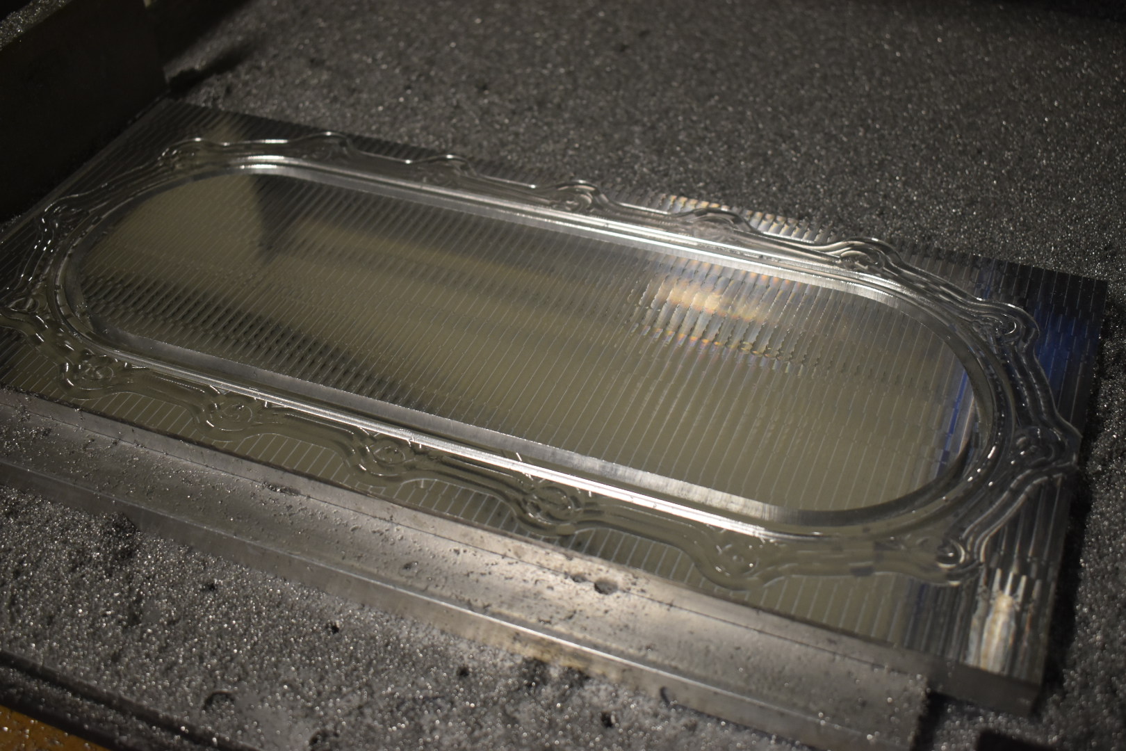
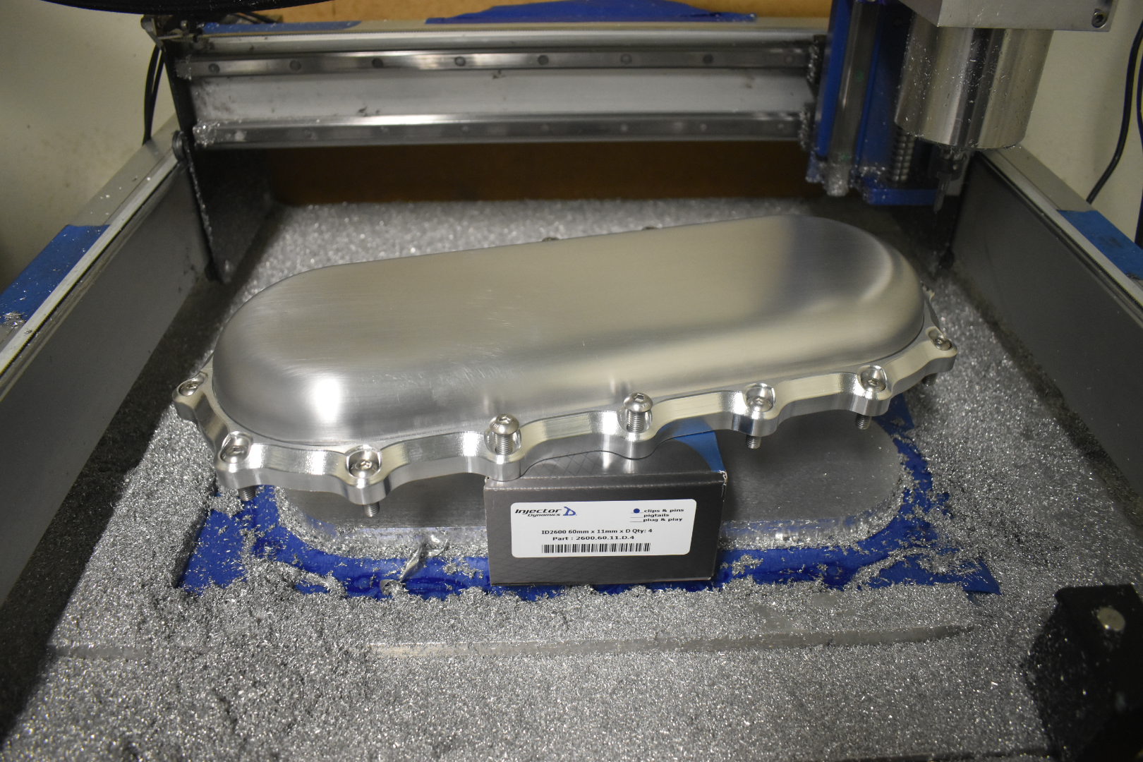
Carbide3d 0.250 SF and Datron 6mm single flute ball just killed it on this project! Side one done and done. These parts are right off the machine, no deburr no polishing, just butter feeds and speeds.
The flip turned out really well with just good, square stock and the 90 degree fixture plate. Superglue/tape setups used for both sides. Fusion360 for cad/cam and Carbide Motion for sender.
Started out life as an 8x18x0.750 6061 plate.
The piece looks amazing as usual.
Are those shareable or part of your secret sauce ?
I’ll share details later but the important part is constant load and slow easy reliable over blazing speed.
When @Vince.Fab creates a part he doesn’t say hold my beer he says “smoke me a kipper I will be back for the tool change”
Love the work #bravo
Jon
Usually I’ll be holding the beer and smoke while watching the passes because I had only bought one piece of material so failure wasn’t an option lol.
@Julien the secret is there isn’t any secret.
The more you run pieces there more you understand the process. The metal is extremely consistent so its easy to learn if that makes any sense.
The full width inner and outer contour cuts were done without a roughing or finish pass. Chipload was 0.0015 with an axial doc of 0.015 and ramp/plunge set at 0.001 chipload. Chip clearing was almost entirely up to the endmill alone and minor light oil spray was used every other pass when axial was past 1xD. Hdz plus this strategy proved very consistent.
The ball milling was a trick from Marv over at Kern. A matching chipload with stepover can produce very good results. The finish pass was 0.002 chipload with 0.002 stepover with bottom to top milling in a ramping toolpath. This was important because the endmill would always be side cutting and the ramping ensures a constant toolpressure. The tool used was a 6mm Datron single flute, this ran at max speed of 24000rpm and really it’s just a beautiful tool.
While not as technical as some of the others, works for me and finish is getting better on each project. I also should add, the bitsetter really makes the workflow and overall product quality much better.
Trying to take surface finish closeups. It’s super interesting to see the differences between linear rail and V wheel motion. Tolerances were set to 0.0001 in fusion
edit the top hole chamfer was done by hand because they still need to be tapped and proper deburred
This is straight off the machine without any polish or post processing.
Hey Vince, when you do parts like this with the tape and super glue setup, how do you remove them once done? I end up using a few different tools and processes to try and get them removed but none seem elegant.
I’ve had to heat them up with my heat gun at times and hit them with a dead blow (using scrap HDPE to protect finish and just to “get in there”). Not very elegant either 
That’s where a nice sub plate comes in really handy. My plate has quite a few holes for bolting that easily let you get under the parts. That particular plate overlapped the edge of the sub and was pryed easily up.
When nothing lines up, usually a scraper that has been sharpened will do the job. The two layers of tape add up to a little over 10 thou thickness so you have a little wiggle room.