I’m using Fusion 360 to model and generate tool paths. I’m trying to do some pocket clearing (have also tried using “Adaptive Clearing”) but keep running into a problem. I set the zero point on my SO3, load the tool path into Carbide Motion V2 and the cutter moves to the center of my stock and the first plunge is WAY too deep. My maximum roughing step down is only set to 1mm. I have simulated the g-code in both Fusion 360 and OpenSCAM and everything behaves as expected. I’m at a bit of a loss because I don’t fully understand the raw code when I look at it. Here is the g-code that was generated by Fusion 360 Pocket.pdf (145.4 KB) Please Help!
…
G21 (metric)
…
G90 (absolute coordinates)
…
S20628 M3 (spindle started @20628 RPM)
…
G0 X20.498 Y43.277 (This the center of your piece?)
Z15 (move down to 15)
Z2 (move down to 2)
G1 Z1.685 F254 (first plunge 254 mm per minute)
S21774 (spindle speed 21774 RPM)
…
I see things like z-0.5 and z-1.5.
Is Z0 set at the top of the stock? How thick is your stock?
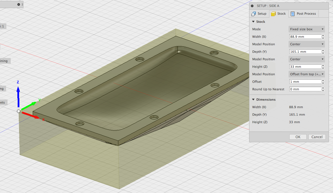
Z0 is set to the top of the stock. Stock dimensions are in the image below. I can send you the fusion 360 file if that helps?!?
so this means that it is going to an initial location and moving down 15mm and then moving down 2mm and then starting movement in the x and y? That seems to be my problem… the confusing thing is that nowhere in fusion 360 am I giving it those instructions. nor does the simulation within fusion reflect this command.
The Z15 says move to 15 mm (height). The next moves says to move from 15 mm (height) to 2 mm (height). The G90 says to use absolute coordinates, not deltas (changes).
This means the end mill should be 2 mm above the material, not inside it. The first plunge is above the material, not inside it. Only the later negative Z values would be inside the material. They look OK for 1mm max plunge.
A good rule of thumb, for any material and end mill, is the plunge depth should be no larger than 1/2 the diameter. The feed for a plunge no more than 1/4 that for a feed for horizontal cut. A 1mm plunge seems fine for any end mill 3mm or larger.
Yes, certain materials, end mills and machines may be able to do more/faster but the above rule is widely accepted as a safe place to start.
I’m not a Fusion 360 user (Evolve (Rhino on steroids) and BobCAD-CAM here) so I’m not familiar with how it does things.
Something isn’t matching up here. Did you set Z0 against the material itself? Commonly that is done by gently touching the end mill to the top of the stock and setting Z0.
Yes… I am jogging the cutter in x and y to the “origin point” that I designated in fusion (bottom left corner of the top face of the stock) I am then jogging in z-axis and touching the bit to the stock and then zeroing all. From there I quit jogging and load up the g-code. The model is not above the stock in fusion it is centered in the x and y axis of the stock and offset 1mm from the top of the stock in the z axis.
You describe the initial plunge as too deep. The G code says something different. Since you’ve got the Z0 of the CAD and Z0 of CAM properly in sync we’ve got to figure out what’s “not making sense”.
Let me explain why things “don’t make sense”. With Z0 on the surface of the stock and absolute coordinates, positive Z is above the stock; negative Z is inside the stock. After doing your touch for Z0 I would back the tool off in Z well way from the stock before starting. Never a good idea to start CNCing with a tool touching stock.
Let’s look at the G code:
…
G21 <- metric
…
G90 <- absolute coordinates.
…
G0 X20.498 Y43.277 <- first rapid move. Center of piece?
Z15 <- G0 is ‘modal’ so X and Y don’t change here. Z of 15 is above the stock
Z2 <- still at X and Y, move to Z of 2 (still above stock)
G1 Z1.685 F254 <- this is the first “cut” command; we are above the stock
S21774 <- spindle speed adjustment
X20.495 Y43.274 Z1.614 F3738.9 <- G01 is modal. This is a “cut”. Z has lowered
G2 X20.487 Y43.266 Z1.545 I-2.122 J2.143 <- this is a cut, part of a circle. A corner?
X20.473 Y43.253 Z1.477 I-2.114 J2.152 <- part of circles, Z is lowering…
X20.454 Y43.234 Z1.412 I-2.1 J2.165 <- …
X20.43 Y43.211 Z1.35 I-2.081 J2.184 <- … All of the G02 - a cut - is above Z0!
X20.4 Y43.184 Z1.293 I-2.056 J2.207<- … Why is there cutting if the piece is embedded in the stock
X20.365 Y43.153 Z1.24 I-2.027 J2.234 <- … which should all be below Z0? Hmmm…
…
G2 X42.932 Y86.866 Z-0.496 I0.635 J0 F5080 <- first negative Z; this is way down from the first cuts
It hard to tell what is going on. The G code is indicating that your piece goes from above Z0 to below it (Z of more than -16). The picture of the CAD looks correct but sometimes it is hard to tell.
Could you please post the generated G code as a regular file? I want to run it in my (pro/prosumer) G code simulator programs.
Could you please post the STL file? If you can also post it as an IGES or STEP file that would be great. You’ll need to do that via the export ability of the CAD package.
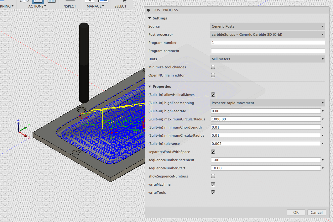
If your using a Shapeoko 3 - double check the switches on the motion board are ALL set to 1/4 step and nema 23. The switches are located on the board, next to each stepper driver connection.
Contents: BoxLid.stl, BoxLid.igs, Pocket1 g-code, screen shot of finished simulation in fusion with and without tool paths shown, and a video of the simulation in fusion.
Unfortunately I cannot check this at the moment because It is my friend’s SO3 and I don’t have access to it at the moment. Going over there sometime this week so thats the first thing i’ll check! She is using it (successfully) with MakerCAM for some really basic profile cutting and drilling… I got a little more ambitious . I’m starting to think that I’m going to need to try another program to generate the tool paths for this, which would suck b/c fusion is relatively idiot proof and also FREE. Also thinking that I should join the Fusion 360 forum and post over there as well.
As always, thanks for taking the time to help!
Thanks! Let me take a look and see if I can figure out what is going on.
The G code you posted earlier does make the geometry (shape) but it isn’t do it the way you describe (all of the part below Z0).
I’ve played with Fusion 360 in the past (early on) and it looked interesting and made correct G code for one of my CNC machines (CAMaster). This could be some wacky setting issue in Fusion 360 but this feels like something is off in the CAD or the CAM (and not necessarily your fault).
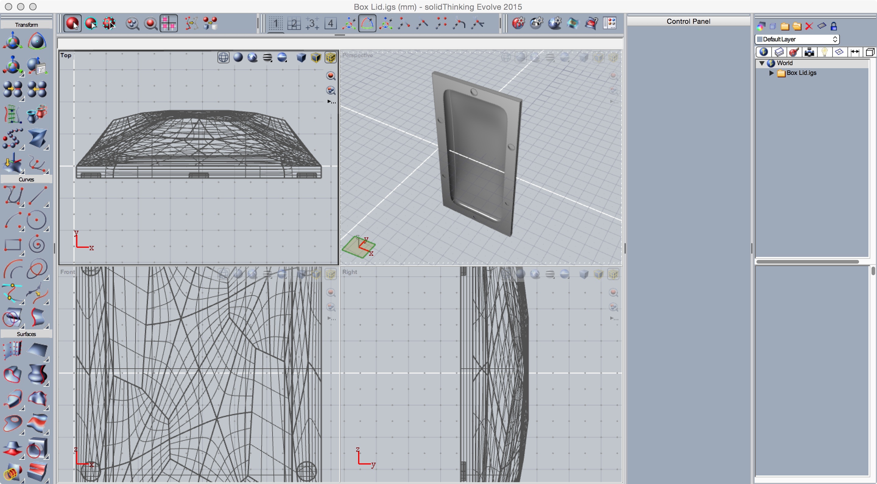
Notice the perspective - Z is up. The red lines are rapid moves, the green cuts. Look on the left. See?That is where the first cut starts - above Z0. Z0 is not the top of your stock - at least as far as the G code is saying!
I’m digging into the IGES file with my CAD program to see if I can figure out what’s going on.
See it? The part spans Z0 just as I explained (upper left hand corner). You need to use the CAD package to shift the piece in Z by the height of the surrounding frame such that the top of the surrounding frame is at Z0.
In MeshCAM you can move the STL around to ensure this before generating the G code… however the easiest way to ensure this is to make the CAD agrees with what you want - top of part is Z0. I was able to take in the IGES, spit out an STL, take that into MeshCAM, translate it in Z, and get the expected G code.
Fusion 360 is generating G code that exactly says to machine what the geometry says to do. The plunges are too deep because the CAD indicates the Z0 is ~2mm into the stock.
In MeshCAM, it doesn’t matter where the CAD origin was placed. The only link between the geometry and gcode is the Machine Origin, which is what MeshCAM uses as the zero point.
The MeshCAM workflow is very straightforward:
Import your STL
Place the rawstock relative to the STL
Place the Machine Origin relative to the rawstock
Generate the gcode, which will be relative to the Machine Origin
Set up your machine zeros to be in the same place as the Machine Origin on the actual stock
Successfully machine your workpiece.
I can’t speak for other CAD programs specifically, but the key in executing any gcode is to set the actual machine zero point to the same place that the gcode was calcucated from. The CAD/CAM zero can be at the top of the workpiece, the middle or the bottom, it doesn’t matter. If the zero is at the bottom of the workpiece, set the Nomad Z zero to the bottom. Gcode is all relative to where you start.
So using my n00be powers of deductive reasoning I think the problem lies with Fusion 360 and the post processing. Fusion seems to be ignoring the orientation that I am defining in the CAM setup and defaulting to the orientation that the model was created in. I’ve tried working around this by creating a new file with the correct orientation form the start and then doing a similar pocket clearing action… results… I get the same funky G-code. I’m going to post in the Fusion 360 CAM forum to see if that’ll shed any light on the subject. If I can’t get any answers then I’ll move over to MeshCAM. The Fusion 360 Forum post can be seen here. Thanks again to everyone for their help.
I do not see any post processor issues… but there could be. I don’t think so.
As Randy and I were explaining there are two ways to fix this.
The G code is diligently doing exactly what you CAD geometry is says. Part of the part is above Z0 and part below. Using the CAD program relocate the entire thing in Z such that the top of the lip is at Z=0. This is a bit brute force but it will align the part with way you want and since the G code generation is exactly matching the geometry the G code will be correct for Z0 on top of stock.
The other way is to do what Randy is suggesting but find out how to do that in the CAM section of Fusion 360. You do the Z relation in the CAM section. In MeshCAM we know how to do this (there is a nice relative button!) but neither of us can speak to Fusion 360.
Oh no, I’m saying just use the current gcode as is, but figure out how far the Z zero is down from the top of the workpiece. In Carbide Motion, touch the cutter down to the stock and instead of zeroing Z, enter the required Z. I.e. if the gcode Z zero is 1.5mm down from the top of the workpiece, touch the cutter down and enter a value of 1.5mm in the Z box.
Of course for the future it is good to do as @mbellon says and learn how to position the origin in CAM, but to get the current job done work with what you have already.
Do you know of any workshops or maker spaces in the Los Angeles area that I could contact or go to and get some sort of one-on-one hands on training with the Shapeoko 3? I’m feeling a bit lost and need some guidance!


 I’m going to post in the Fusion 360 CAM forum to see if that’ll shed any light on the subject. If I can’t get any answers then I’ll move over to MeshCAM. The Fusion 360 Forum post can be seen