Hey guys… new CNC’er here. Tried a anagrammed spool holder the other day that was on material too small for the file I downloaded, but over all it went well and I learned some stuff.
Now, I’ve got the awesome 4’ tall/wide cable spool that I’m using as a table (I’m an electrician and I just knew the day would come that this spool would come in handy). I’m trying to make some customized drawers for various parts and my laptop for when I’m working on the machine or in the shop (garage to my wife).
Problem is this: I added a bunch of bits I bought from Amazon to the tools database and have assigned all of my toolpaths these bits for the sake of accuracy. I got Gemini to help me with the values for each bit. I’m not sure any of that matters, though, because when I open my file - or even when I save it as GCode (save Toolpaths), it lists the wrong number of tools and the assigned tools are incorrect. I put a lot of work into this first project and I’d hate to start over with assigning toolpaths, or worse: a new drawing {{GASP!}}.
Does anyone have any insights as to why Create would export the wrong tools for the toolpaths? keyboard drawer.nc (1.2 MB) keyboard drawer.c2d (228 KB)
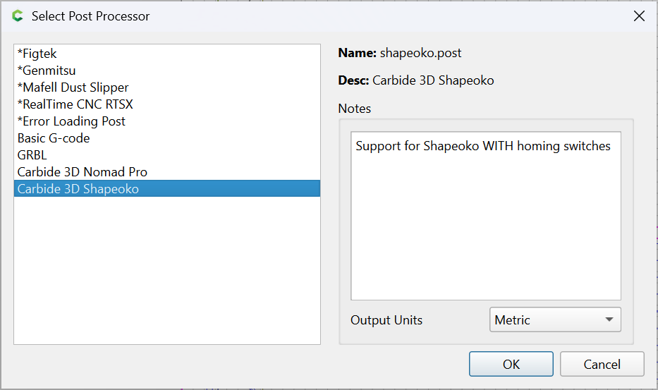
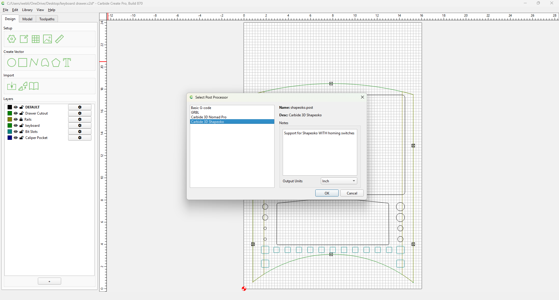
These are the only options I have and I tried the basic g code and the highlighted one: Carbide 3D Shapeoko. In both cases it specifies the wrong bits and they don’t align with what my toolpaths are set to.
I appreciate the help. I actually worked with Gemini on the issue after I couldn’t figure out why nothing would change in the output to gcode. Seems CC doesn’t always update the actual gcode if you make a change to the tools in the tool library unless you reselect and recalculate the toolpaths. I went through each toolpath and did just that (and adjusted some values like ramping, etc.) and that did the trick.
However, this brought up a new issue for me: the first toolpath is a pocket, and somewhat large at that. For this (since I don’t have my McFly mortising bit yet) I used a Diablo 3/4" mortising bit. Please note that for this pocket I’ve set the depth to .1" deep. I wasn’t paying attention the first go around because it was the wrong bit for the job, but just like the first time the bit plunged into the stock probably half an inch. In the gcode, the simulation and all of the settings, the depth is set to .1", but I can’t figure out why the controller read something different. I couldn’t find the z-depth that CM thought it was supposed to go to, but I did test the Z-zero and it was correct to the stock height.
Liam,
A quick nomenclature issue- the McFly is a surfacing bit, not a mortising bit. A surfacing bit prepares a flat surface (usually set up to do wide shallow cuts). A mortising bit makes a deep hole to accept a tenon to form a mortise and tenon joint. They are relatively narrow and upcut to clear the waste.
Create NEVER recalculates the toolpath if you change the tool in the library. You’d have to either manually change the settings in the toolpath or reselect the tool.
I’m not sure where I got the crazy ideas I did with the surfacing and mortising bits. I had thought I saw a video with someone surfacing a pocket with the type of bit I’m using. Funny enough, before I saw your response I finally figured out that my 3/4 diablo is what’s causing all of my grief. So much for trying to cut time… But this is how we learn, right?
Now, I apologize for continuing this off-topic, but I guess I’m not 100% following what you’re saying: is NOT the bit to use for this since it’s a mortising bit, but is the McFly (surfacing bit) capable of doing a pocket, or is this another case of not really meant for enclosed patterns?
The McFly is a surfacing tool — if I used it in a pocket I would only do so to remove a very thin cut at the bottom after roughing to one chipload thickness or so of the finished dimension.
Yea, I’ve been trying on my own to figure out what’s going on, in some cases passing some of this to Gemini for some ideas. Gemini basically said the z values are correct like you did, so it suggested that the bit is being pulled down - whether it’s coming out of the collet, which I’ve confirmed is not happening, or because the stepper motor connection to the screw might be loose. I don’t believe that’s true, but for the sake of argument, is it normal to find a little bit of oil along the vertical rails on the Z-mount or the screw?
Have to be honest, this whole process is making me feel pretty stupid, but I suppose that’s to be expected with something you know next to nothing about. My wife says I should try a simple project just to see if it behaves the same way and see what happens.
Thank you, by the way, for helping me understand the surfacing bit’s purpose with pockets. I’ll keep that in mind going forward.
If the Z stepper get pulled out of place (lost steps), Z will be off if you touch off your zero point afterward.
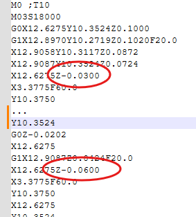
Not sure I understand the “wrong tool” thing. The only thing in the Gcode that’s pertinent is the “t” word
M0 ;T10 (manual tool change. M0-Stop, T10-Load tool #10)
M6T10 (auto toolchange, M6-toolchange, T10-Load Tool #10)
CM on M6 stops, prompts for Tool #10, then measures the tool if BitSetter is enabled.
On M0, it just stops & prompts for tool.
So as long as the first tool number is 10, either is correct.
The wrong tool thing was in regards to a problem with the g-code updating after I edited the tool library. I’ve already figured that part out (and thanks for those that helped explain that).
Where I stand today is that when I start my project, the first toolpath is a pocket that I was using the diablo mortising bit to cut, but I’ve since changed it to a 1/4" spiral endmill. The depth of the pocket is 1mm, so not very deep at all. I set ramping on all toolpaths as suggested in the guide videos on this site, but use a depth of 10 deg. When I tried running this new toolpath definition, the initial cut takes three passes that cuts to a depth of close to half an inch. But the g-code is showing accurate cuts. This is why Gemini is suggesting a mechanical issue. Any thoughts on the light coat of oil I found on the screw for the Z-axis or the rails? When I try to move the screw by hand or move the router up or down by hand (while the machine is off) it doesn’t budge, so I’m not sure Gemini is correct in this assessment.
It’s an upcut bit. I created a “coaster” just to see if the machine would behave the same, and other than a misunderstanding of the settings for the cutout toolpath, it performed as it should. Unfortunately I don’t have time to test out my project again today, but last night I created a copy of the project file and re-did the entire set of toolpaths, keeping the operations grouped by bit and ordering the operations to try and minimize stress on the bits themselves (starting with a v bit for contours before using the endmill on pockets, for example). But somehow I think it comes down to corrupted measurements as I switched the project file a couple of times from inches to mm. This time around I kept it the same all the way through.
I would like to point out that in the cutout toolpath the expression editor doesn’t convert from inches to mm or vice versa. Not sure if this is a bug or not, but just an observation. I just have to remember the mm value I’m looking for.
That’s what I mean… I wasn’t able to convert using those expressions. I would type .25in= and it would just stay like that. But that only happens in the job setup and the cutout toolpath. Everywhere else it behaves as expected.