I’ve only had the machine for a few weeks and have only done about a dozen projects on it but it’s suddenly not keeping to the programmed shapes. I ran a circular test cut to see what’s up and you can see that in some areas it’s not keeping to the toolpath and veering slightly away. Any idea what this issue might be? It was working fine up until a few days ago.
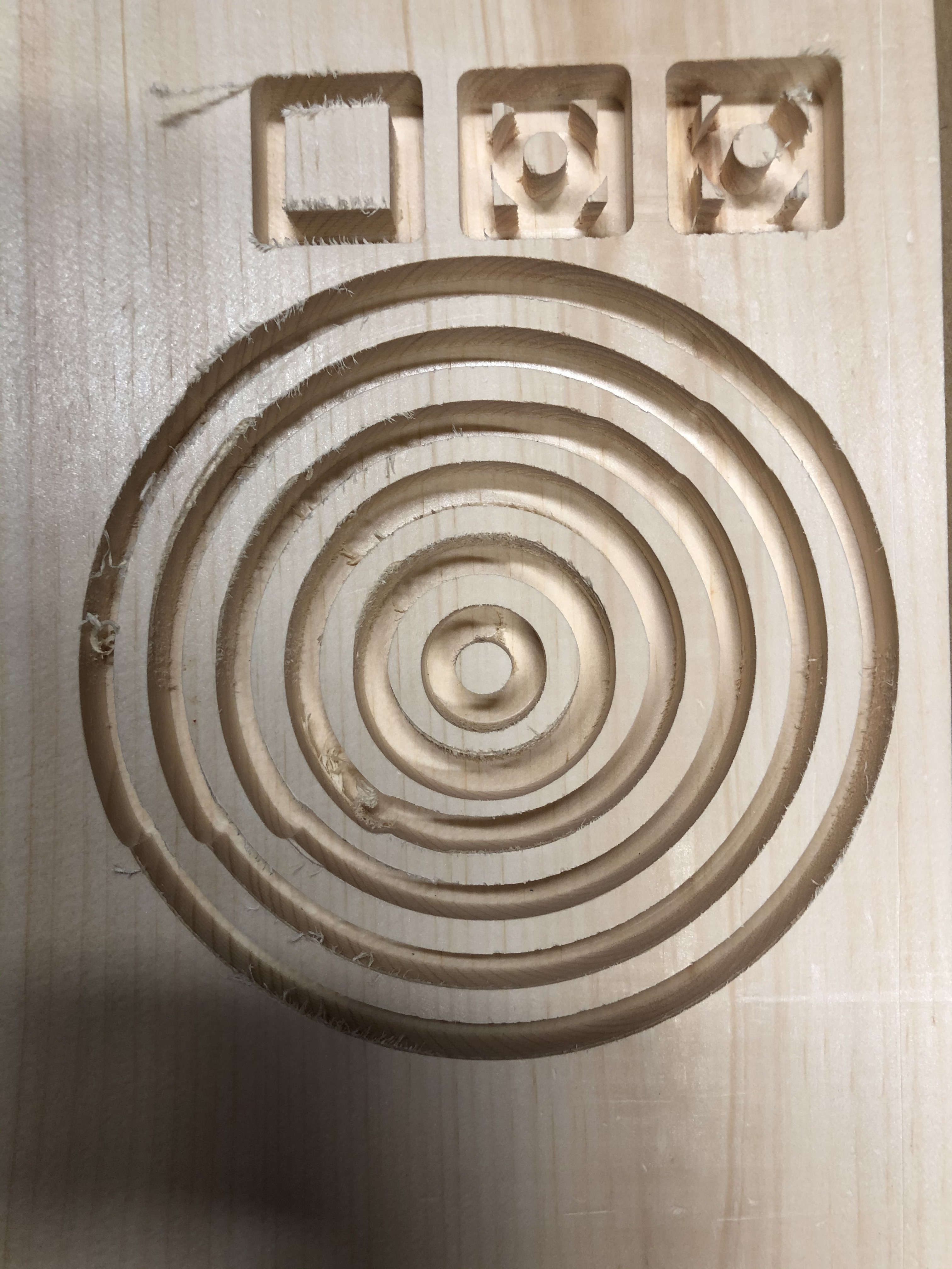
I havent had this problem. But it seems to be happening at the same place in your design. So it makes me think that it’s a physical problem with the machine. I would check for damage or build up on your rails or v-wheels. If you don’t find any sawdust built up on your wheels or rails, I would check the wheels for for proper adjustment and or flat spots. Next I would check the belts for proper tension and possibly missing or damaged teeth.
3 Likes
Thanks Jon,
I’ll do a good cleaning of the wheels, I’ve been working without a dust collection system of any kind so there has been a bit of build-up. I have a dust collector coming this week.
1 Like
In addition to checking the machine mechanically I’d recommend adjusting your Toolpaths so as to reduce tooling engagement — avoid slots where possible (add geometry and cut as pockets, using a smaller Endmills if need be).
2 Likes
When you don’t have DC you will get a build up of saw dust an both wheels and aluminum extrusions. I use 3M finishing pads white to clean rails.
I stood over mine with the vacuum hose until I got the dust extraction sorted to avoid jamming up the cut with chips. As Will says, this slotting toolpath is hard for the machine and easy for things to clog up.
It sounds like you’ve had your machine for just about long enough to go through a full check of belt tension, lock-screws on drive pulleys, V-Wheel tension etc. as whatever was going to come loose is probably starting to.
3 Likes
Thank you for all the advice, my normal cuts aren’t slots like that, I was just testing to see if the circles were true. But I will avoid that in the future. In retrospect I should have tried vacuuming while it ran, I’ve been just cleaning up after the cut but it sure makes a mess.
As an aside to the slotting point above, is there a preferred bit for doing drill holes in wood? Like a cribbage board? I’ve been using a downcut bit but even with pecking I’m getting burning at the bottom of the hole. The hole is the same size as the bit.
Based on that statement I assume you must be using VCarve or similar software ?
Endmills are bad at drilling, downcuts are even worse than their upcut counterparts since they push the chips down, with nowhere for them to do when the hole size is the same as the bit, so I would not be surprised it things got better when using and upcut. Peck drilling is a nice option to mitigate that problem, but make sure you did not unintentionally set a dwell time for when the tool is at the bottom of the hole:

Alternatively you could use a smaller endmill and mill the holes as pockets (but it will take a bit longer)
Some folks have been using 3/16" or the next smaller metric size for holes — depends on the size of pins they’re using.
I’ve been using Fusion 360 for everything so far. I’ll try an upcut and see if I get any tear out. Do they make regular drill bits with the standard CNC shanks? Hole drilling seems like it would be a fairly common procedure and they seem to have bits for everything else.
1 Like
From what I’ve read and tried myself drilling is a no-no on this class of high speed spindle CNC machine.
On a big mill running at 1,000 RPM a big drill is a good way to hog out a lot of material quickly but you’ll need solid carbide drills to go at anything near the speed our spindles run at, they’re not cheap.
Also, drilling will still give you a messy hole because drills cut a triangular hole generally with tear out on one or both sides.
Milling a hole using the bore CAM toolpath in Fusion lets you cut clean holes in almost anything, but you need a smaller cutter than the hole you plan to cut so that it can spiral down the hole cleanly. I’ve put 4.6mm holes in the edge of 5mm Acrylic like this without blow-out. If you want counterbores at the top etc. then a contour toolpath works well for those.
If you’re using Fusion then I’d suggest you try a roughing and then a finishing toolpath, then you can use an upcut cutter which will clear chips well for the roughing toolpath and then come back with a downcut or compression cutter to do the finishing. There’s also plently of low helix upcut cutter out there, but beware, they don’t always clear chips as well as the high helix cutters.
Have a look at this thread;
For some examples of different cutters and roughing / finishing strategies in ply.
HTH
4 Likes
what @LiamN said. You’re better off using a smaller endmill and pocketing. Sometimes in Fusion360 I use an inside contour toolpath with helical ramping as a “drilling” strategy:
- I use a tool smaller than the hole diameter,
- then I create a contour toolpath based on the hole circumference, setting up a single pass at full depth.
- I set the ramping to helix, and define a very small helix diameter, such that the sum of the helix radius and cutter radius is just short of the hole radius.
While the tool is plunging, the helical movement will help clearout the chips, and once it reaches the bottom of the pocket there is very little material left on the walls to remove, so the actual contour cut that starts then runs at full depth but without any significant effort on the cutter and it acts as a finishing pass.
Of course this does not work well for deep, small diameter holes.
2 Likes
The experts are above/below me in this topic, but I plan to follow this post from @MadHatter for making many 0.125" holes using peck drilling. I bought some of the carbide bits (which are made for drilling PCB holes) – we’ll see how it turns out!
2 Likes
So I figured out what my problem was and was thankfully an easy fix. I had stacked a second spoilboard on top and the double sided tape had started to let go after a few dozen projects. The shift was due to the piece moving under pressure but not so much that I could see it moving, it just screwed up the cuts.
I’ve started using the super glue and painter’s tape method to hold down my material but maybe I’ll find a better way to hold down the spoilboards.
4 Likes
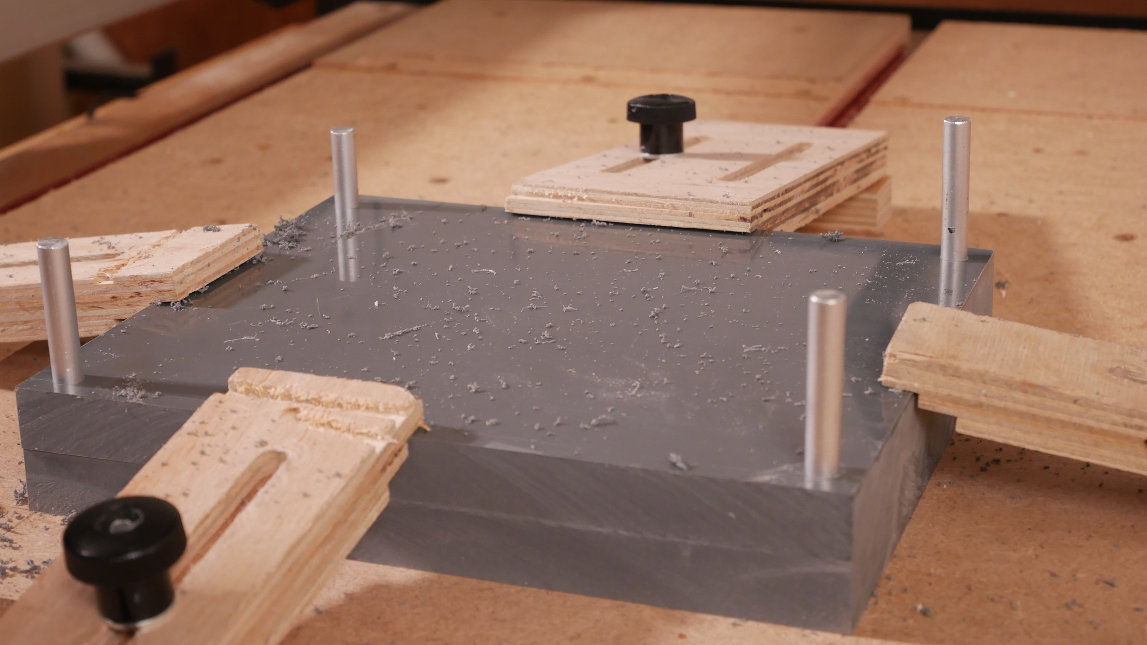
I’ve had reasonable success making jig boards with locating pins (8mm aluminium rod) and using the 3M blue tape suggested in this thread;
It sticks way better than the generic blue masking tape I was using before, so well in fact that I have to file a chamfer onto the bottom of the stock so that I can get under it to pry it up at the end of the job.
I have a couple of locating pins along the Y axis in the jig board to align it and then use a few M6 bolts into threaded inserts in the baseboard.
I have the Shapeoko bore locating holes through the stock matching the layout it bored on the jig / spoilboard below, in this case it’s so I can flip the part to machine the other side;
The clamping on top is really just for my comfort, given I can almost pick the machine up by the workpiece ![]()
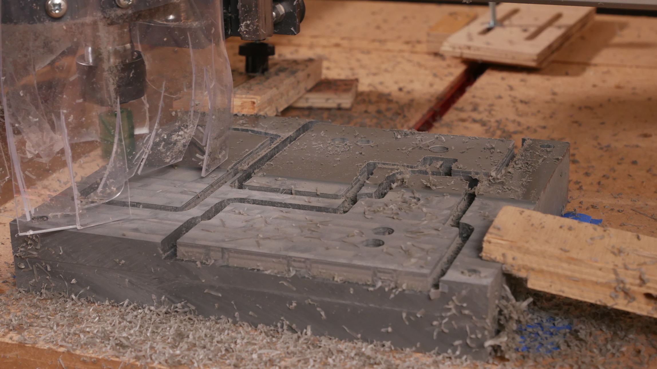
The pins are soft aluminium rod so that it’s not instant disaster if I send a toolpath or rapid through them. Make sure you extrude bodies for your clamps and locating pins in your fusion model then set them up as fixtures in your CAM job setup and “stop on collision” will then stop if you hit them during a CAM simulation.
Here I’ve got extruded cylinders larger than the locating pins and placeholders for my clamps to check if I’ve put too small a clearance height in and am going to rapid through them (again).

3 Likes
This topic was automatically closed 30 days after the last reply. New replies are no longer allowed.