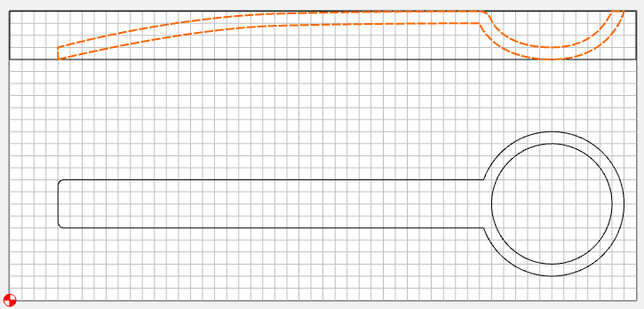
I want to make a dipper for water in a sauna and I do not know how I would go about hollowing out the dipper end to hold water.
Can anyone give me advice on this? I have uploaded a pretty basic file of how I started it.
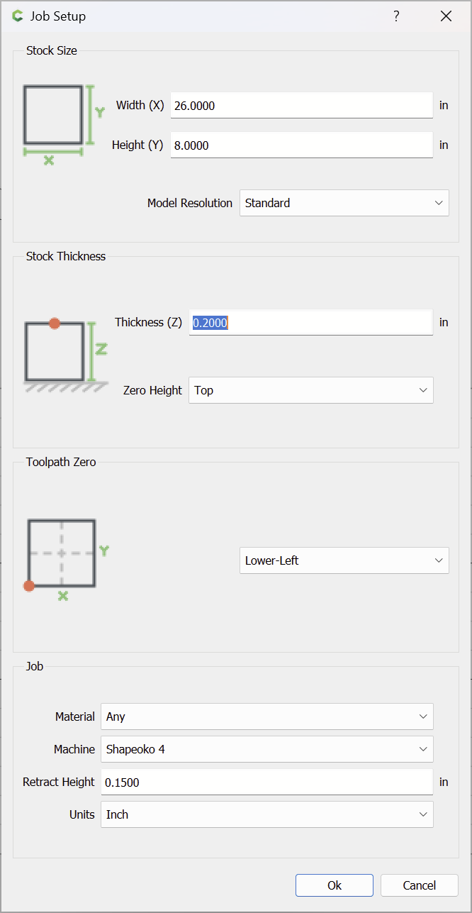
I only have Carbide Create, not the Pro version.
What end mills would I need and how would I create the tool paths? Any other tips on this project? I have never done anything even close to this.
If you have difficulty with this, let us know and we’ll walk through this with you — just confirm the dimensions, and if possible, draw up a side view.
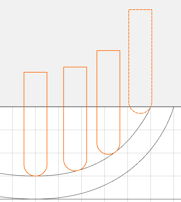
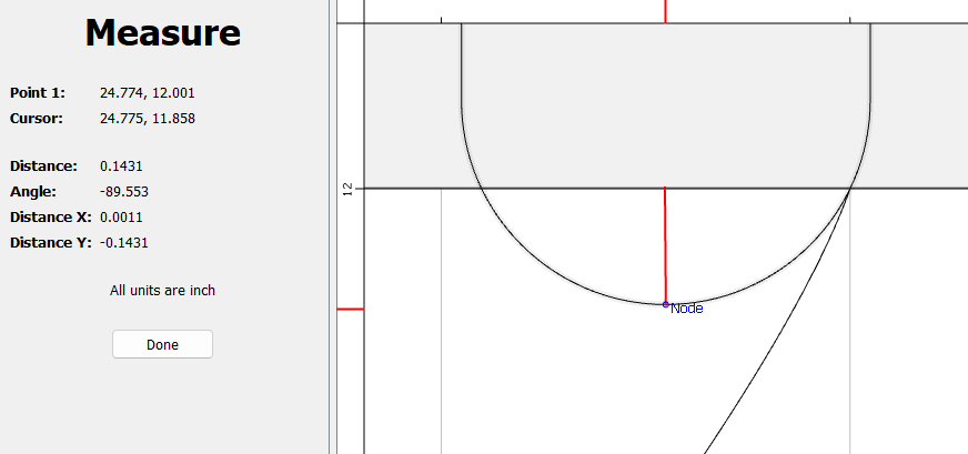
Use the bottom center node for the tool position to create circles to cut and determine the depth at each circle. Note the tool center point will not be the contact point on the spoon.
@WillAdams
Thanks for the reference as well as all of the projects you illustrate for us.
@Tod1d
Thanks for the visual concept, it helps to see this example. Would this be used as a 2D tool path in which concentric circular paths are cut or is this being set up as a 3D tool path to cut left to right and descend towards the middle?
The visual concept @Tod1d showed is the same as I suggested.
It is using 2D toolpaths in the XY plane cut to the matching Z-axis depths — if you’ll draw up a side profile or vet the images above we can walk through this with you if you have difficulties.
Thanks Will, I have this on my to do list but even this initial information gets me going in the right direction. I’m still learning the mechanics of the design phase need to work on these type of projects get farther up that curve. What little designing I have done so far is getting easier as the repetition for key strokes for specific actions as well as my understanding of the software workflow itself.
You know like, putting in the diameter vs the radius for a counter sink hole operation…. And seeing the .25” centered hole in the simulation for a piece of stock 1” wide and wondering why the hole looks half as big as the stock itself vs a fourth the size!
What Will said ^, it’s the same as the spoon example above. Just a little extra illustration for clarity.
These are also referred to as “Z-level” toolpaths. A series of 2D paths cutting horizontal sections through a contoured 3D surface.
Coincidentally, I want to make one of these & the accompanying bucket as well. Just need to get my “round tuit”.