How to make Filler Strips on an XXL (same concept for Standard)

While it’s quite straight-forward to make MDF filler strips on an XL:

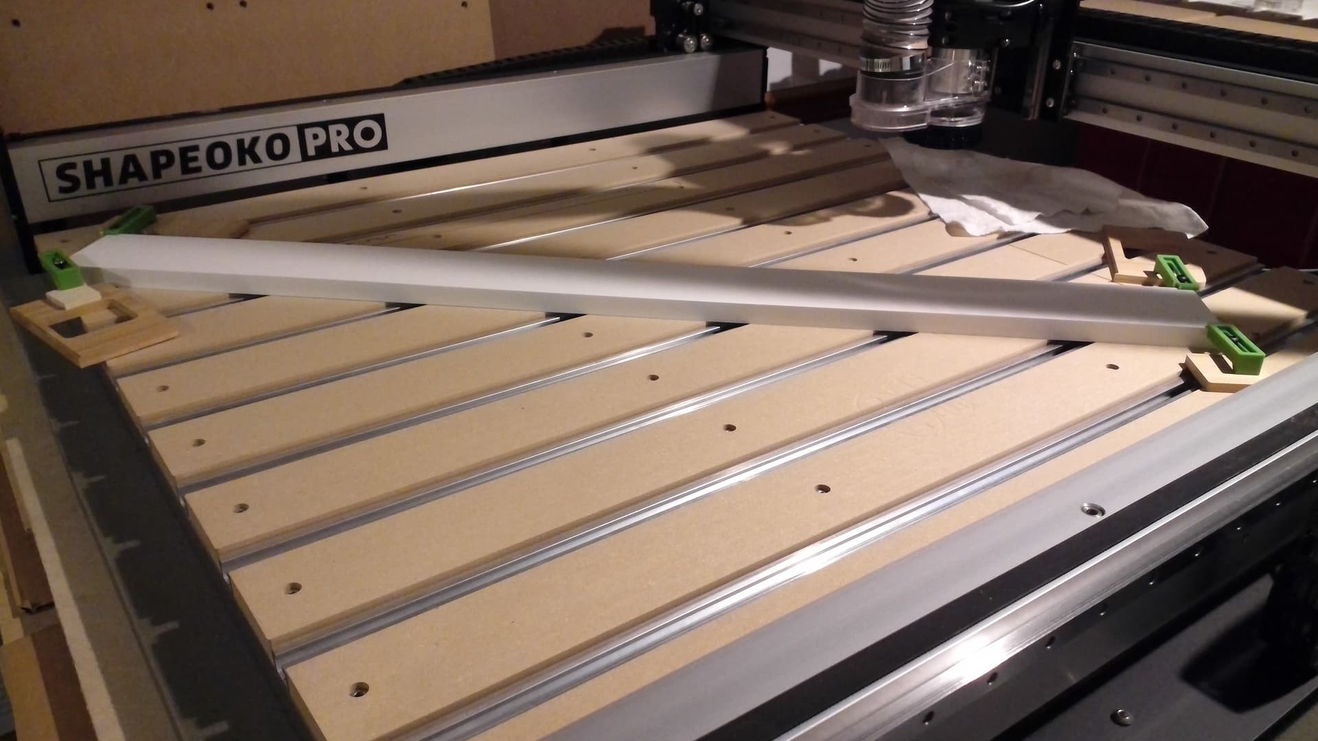
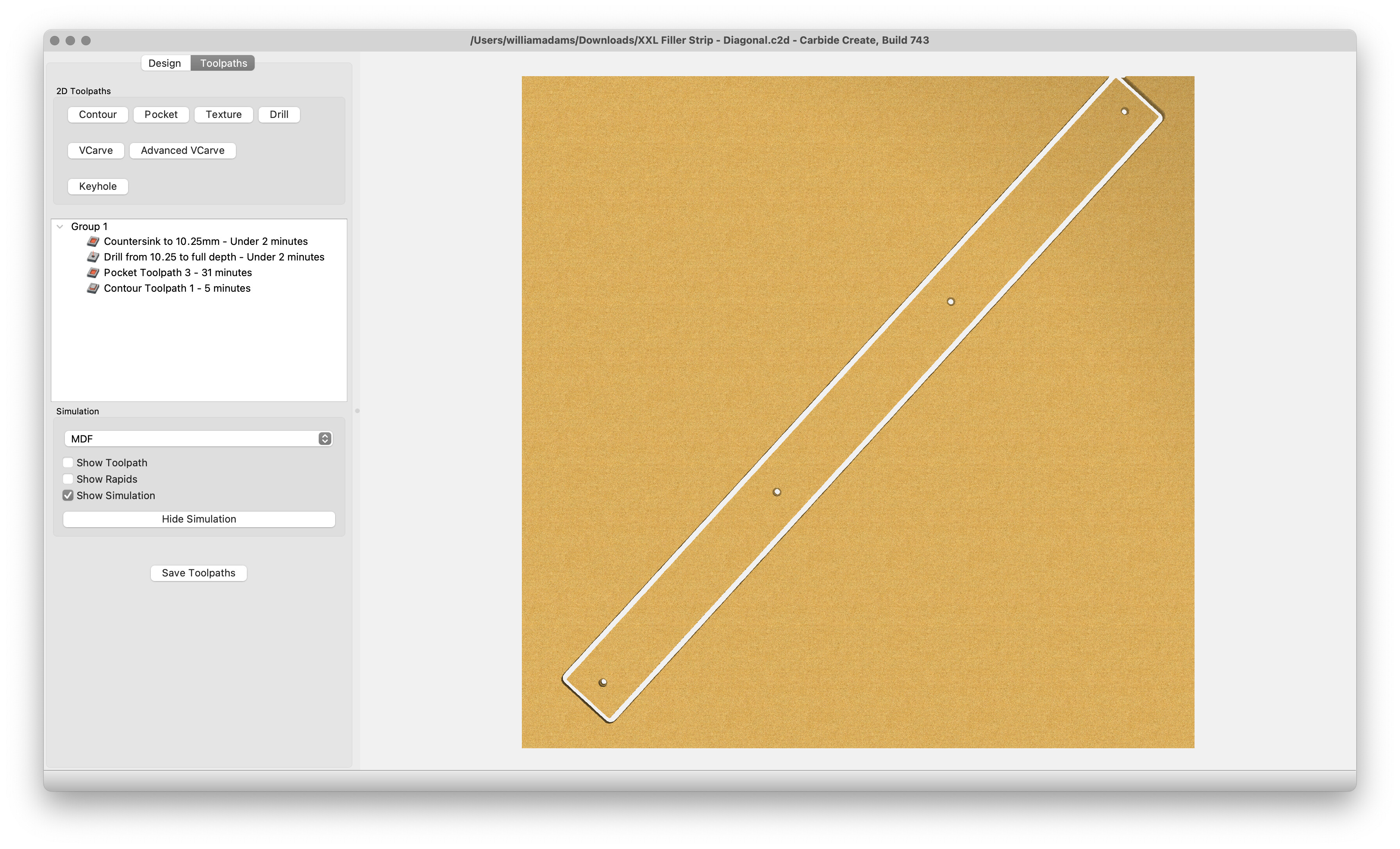
Geometry isn’t so kind on an XXL or Standard w/ their essentially square bed.

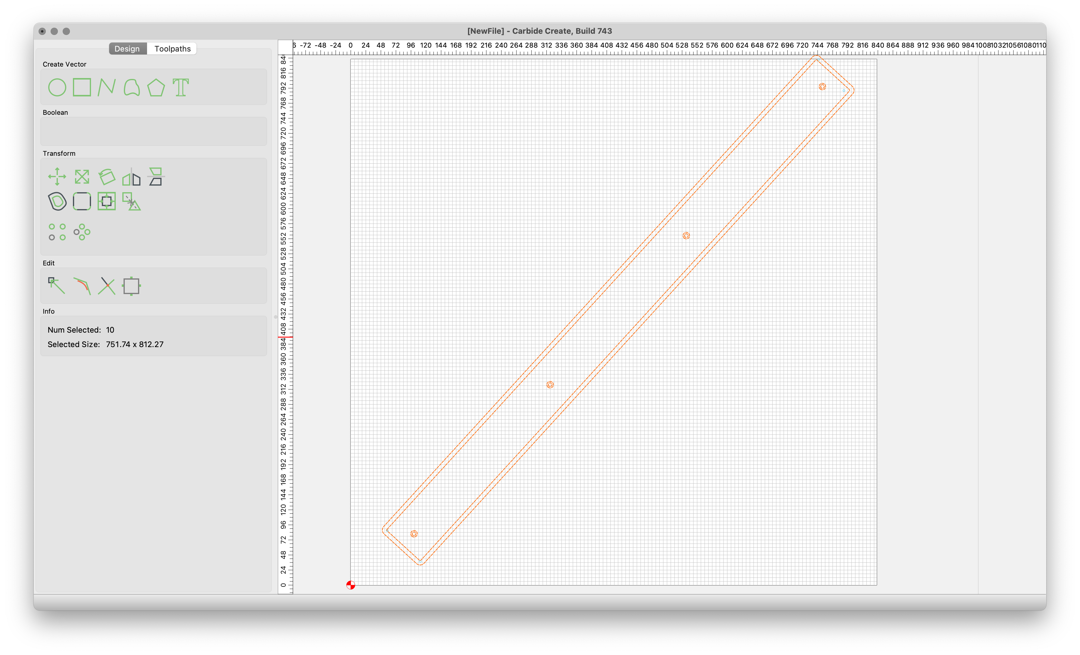
Making replacement filler strips requires that one do a bit of rotation to make things fit, and source narrow boards, rather than large sheets.

First, go to the local lumber yard and buy a board of suitable dimensions (greater than 40" in length, wider than 3" or so, and as close to the 3/4" thickness as is possible). One option is Azek “Exterior PVC Trim 1 x 4 x 8’ (nominal dimensions, actual dimensions: 0.75-in x 3.5-in x 8-ft)”:

https://www.lowes.com/pd/AZEK-Actual-1-in-x-3-5-in-x-8-ft-Trim-Board-PVC-Board/1000507559

That a 4x8’ sheet is only a bit more:

https://www.homedepot.com/p/AZEK-Trim-3-4-in-x-11-1-4-in-x-8-ft-Frontier-Trim-PVC-Board-AF10012096/204790968

is an interesting look at the economics.

Another option is MDF boards — these are more affordable, but aren’t as thick, and usually are pre-primed.

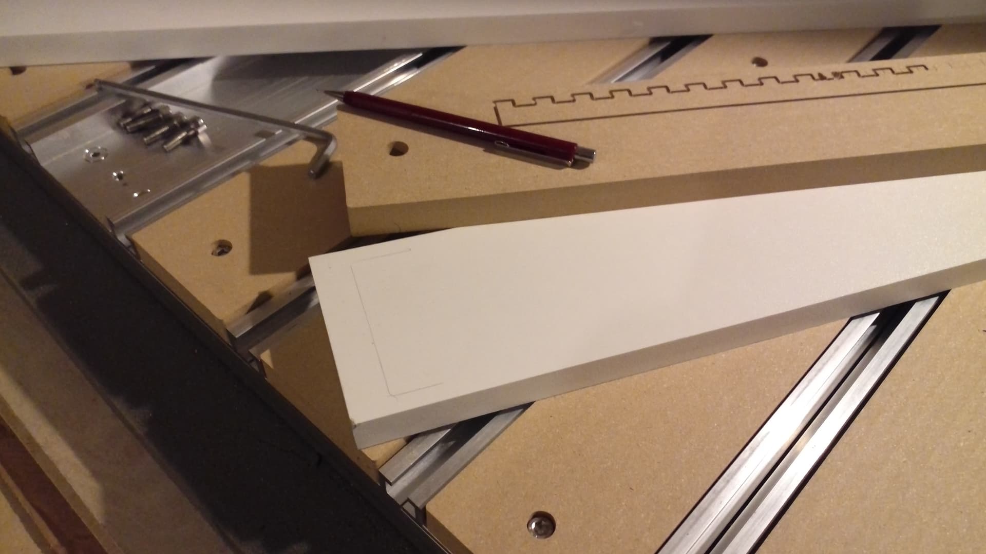
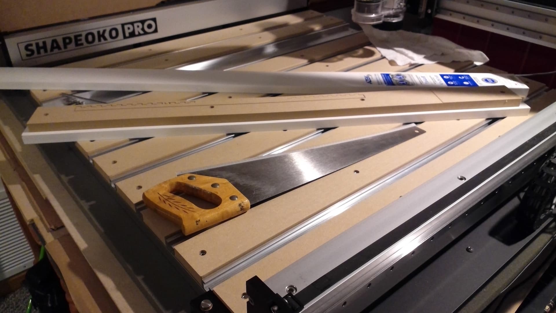
If you don’t have a truck or van, bring a handsaw (or buy one while shopping) and cut it in half or so that it will fit in one’s vehicle (probably best to cut a bit longer than 40" so as to maximize the length of the final off-cut):

Necessary tools:

  • 4mm hex key (to remove and replace MDF filler strip)
  • hand saw
  • Shapeoko w/ trim router and suitable endmill
  • suitable workholding

Necessary materials:

  • suitable lumber
  • MDF filler strips in need of replacement

First step, either measure up, or draw up a filler strip — there is one at:

Hybrid T-track slats - XXL.c2d (110.5 KB)

and then either draw up the physical state of one’s machine, or place the board on the machine, clamp it, and then measure its position using the machine and do the trigonometry to match the rotation and position the machine and some objects to verify the positioning — we will do the latter.

First, mark up the board using the MDF filler strip so that you will know where the cuts will be made and can clamp it in such a way that the clamps will not interfere w/ the cut:

Then power up the machine initialize, load a tool, and move to the left-most and forward-most possible position and set XY zero there.

Then launch Carbide Create, create a file w/ the origin at the Lower-Left and the size equal to the nominal working area of the machine:

Then jog to each corner drawn on the stock and draw in a matching circle which matches the endmill diameter (note that this will be more accurate w/ a small pointy tool, so select accordingly):

(make sure to use the same units in both applications)

Then draw a circle:

Then use the Move command to move the center of the circle to the same coordinates:

Repeat for the other 3 corners:

Send all four circles to a suitably named/coloured layer and lock it, then import the file for the filler strip:

Move and rotate until the corners line up reasonably well:

Set Z-axis zero relative to the surface of the stock and then send the G-code:

This topic was automatically closed 30 days after the last reply. New replies are no longer allowed.