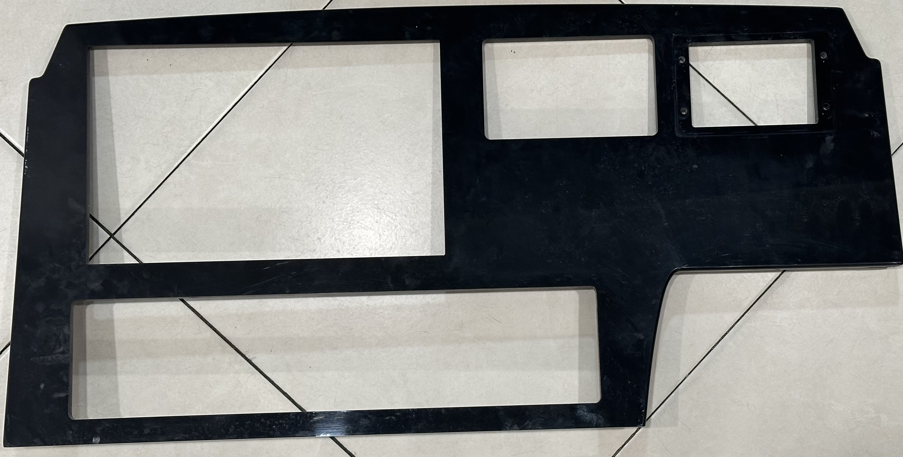
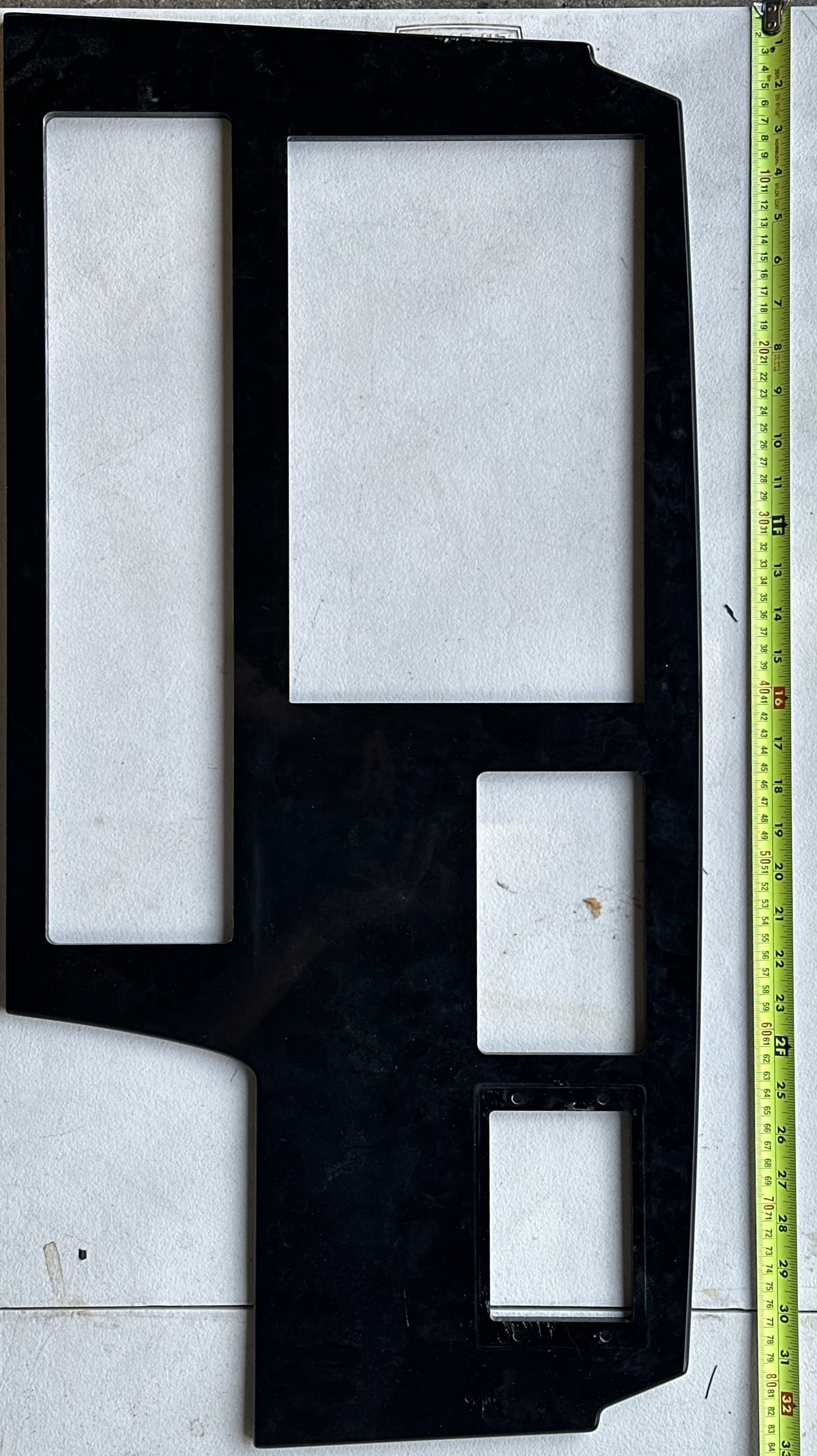
How can I measure these curves and get them perfectly as shown in the photo? There’s many curves and a curve on the top on the Dash Panel
Is it possible to lay the panel out so as to get a perfectly level photo of it with enough of the floor in the background to confirm the size/scaling?
If you can do that, then you can just re-draw per:
If not that, surround the curved areas w/ some rulers and re-draw based on those dimensions?
Is the part conductive and small enough to fit on the bed of your machine? If so, you could put it on the machine and probe it per:
(maybe covering it in foil would work for that?)
1 Like
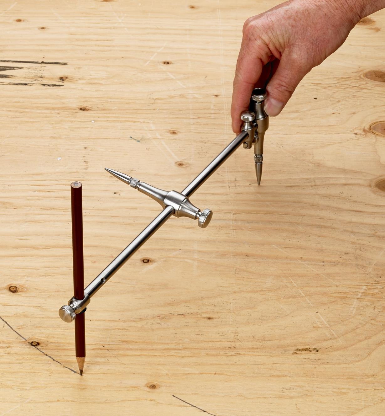
If you think the top curve is a perfect curve then on a piece of large paper draw a set of circles about the size you think. Use the same center for each circle. Then lay your panel on top and move it to the various sizes until you find which one matches. As an alternative you could use a beam type compas and keep expanding it until each end matches and the center as well. Then you could draw a circle and measure it to get your curve radius.
Another alternative would be to take this to a copy shop that has large format scanner and copy it and get it digital and convert it to an svg. Then you could import the svg into CC. Just take a physical measurement of the object and create a rectangle that big so when you import it in you can size the svg to life size. Sometimes when converting the object can be bigger/smaller than the original size.
1 Like
First tape small grid graph paper to the back.
Option1:
- take to work and scan to PDF to email on their fancy copier (this helps avoid parallax)
- use Convertio PDF to SVG
- import svg into CC
Option 2:
- take pic with phone ( this brings in more parallax error)
- email to self
- open jpeg in CC and trace using the graph taped to the back to correct where parallax error is noticeable.
Neither option is fun nor perfect.
1 Like
To reduce distortion, you should stand as far as possible away from the item, and zoom in to take the picture. You also want to take the picture square on. If you can, hang the item on the wall (over a contrasting color), at the height of the camera.
1 Like
How close is “perfect”? I only see 2 “curves”, the top edge & the left side of the bottom right cutout. The rest all looks like prismatic / parallel lines. I can’t tell if the left & right edge are tapered from the picture.
A flat bed scanner would produce much better results than a camera. But I think just measuring & drawing it would produce the most accurate results.
1 Like
Agree w/ @Tod1d if you just prepared a dimensioned drawing most of the lines would simply fall into place, then you can make the couple of curved sections, print them out and check them and adjust as needed.
1 Like
All good suggestions, and I’ve used a combination of these techniques to help two friends rebuild the dashes for their private experimental airplanes. However you choose to get there, you can cut samples for test-fits on cheap 1/8" masonite or the 1/8" dry erase board material they sell at Home Depot or Lowes (black on one side/white on the other). Or 1/4" foamboard.
1 Like
This was another one I was able to get. For tracing, I think I can possibly do it with the acrylic since it has a protective paper on top
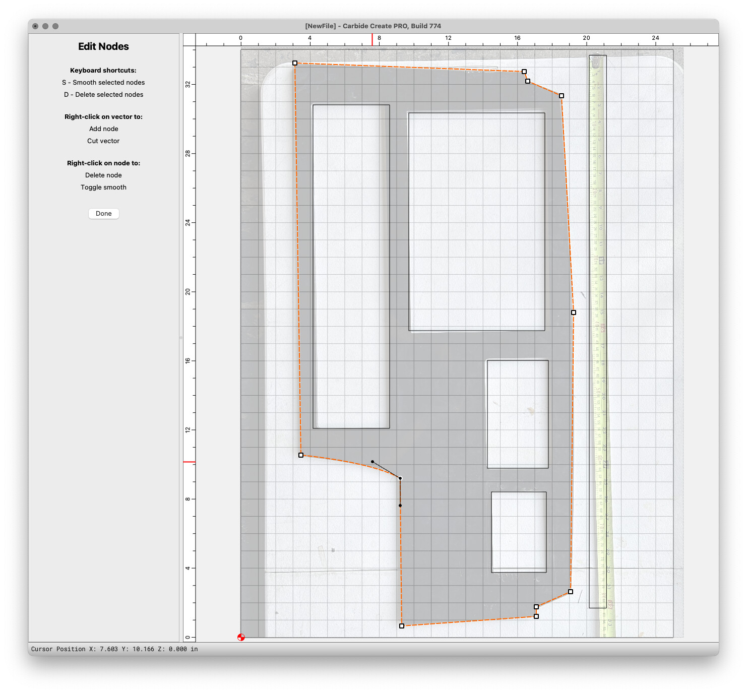
Something like:

Then draw things up and go into Node Edit mode:
Here is a link to the file in a Google Drive.
(too large to upload here, even if zipped)
It will be necessary to check/adjust the size/placement of the rectangles and adjust the outer curves, and adjust corner treatments.
1 Like
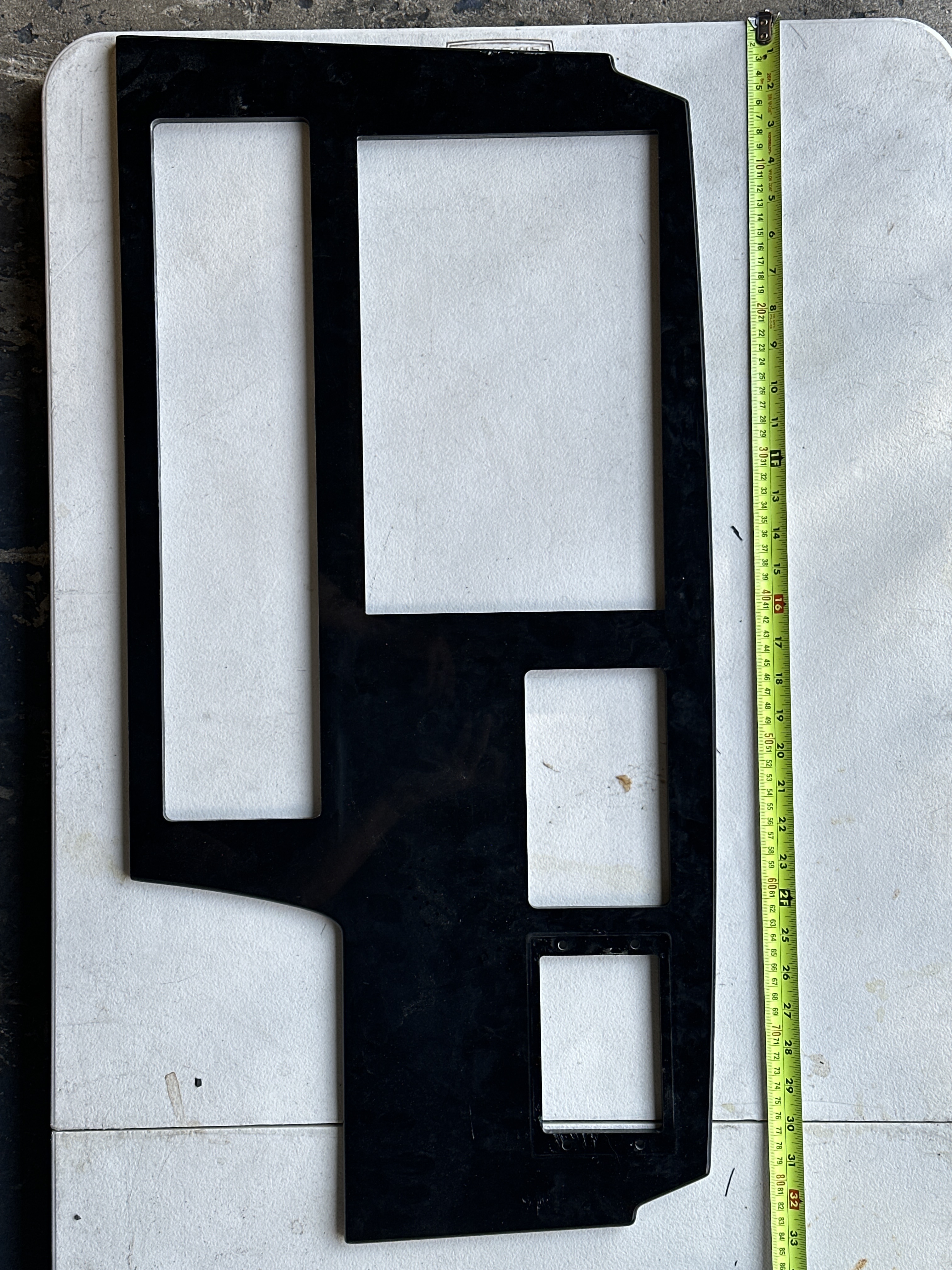
I would lay the piece on a gridded cutting mat and take as near level a picture as I could get; that should give you enough grid points to reproduce the dash.
2 Likes
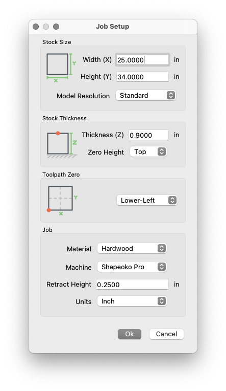
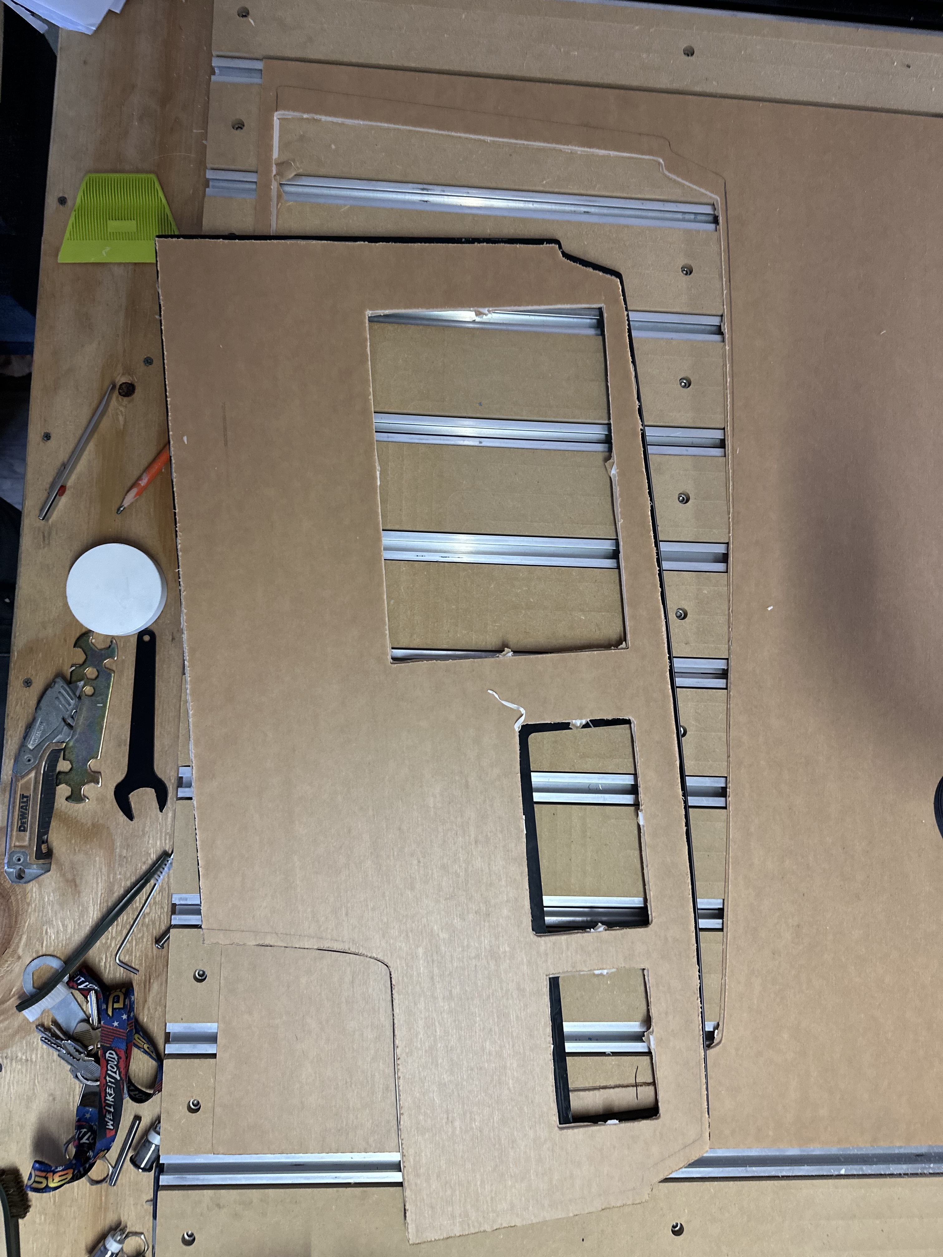
I tried it and this is how it came out
The bigger square hole is different since the client is asking for a different gps system. I almost got it but just came a bit small
1 Like
If you have true curves and you can measure them accurately and precisely, you can use math to figure out the radii. Measure the distance between the end points of the curve – call that distance A.
Measure the distance at the center of the curve from the straight line between the end points and the arc. Call that distance B.
Now using math and the basics of a right triangle you can figure out the radius – call that R because the square root of the radius equals the square root of the sum of the legs of the triangle, or X^2 + Y^2 = Z^2
In our case:
X = A/2
Y=R-B
Z=radius
so
(A/2) ^2 +(R-B)^ 2 = R^2
Plug in your measurements for A and B. Let’s say for example that A=12 and B=0.25, just in case you forgot algebra, this would result in:
(12/2) ^2+ (R-0.25)^ 2 = R^2
Or
6^2 + R^2 – 0.5R + 0.25^2 = R^2
Or
36 +R^2 – 0.5R + 0.0625 = R^2
But the R^2 on each side of the equation cancel each other and shifting the variables around yields:
36.0625 = 0.5R;
R= 72.125
Not bad considering it’s been literally 50 years since algebra class!
1 Like
If you need precision in the thousandths range:
Run a test indicator along the arc a known distance and record the measurements. Using the chord and/or arc with the following relationships, you should be within your machines tolerances.
Just remember t = theta, so set your calculator appropriately (radians vs degrees).
Or just trace and scan! ![]()
I’ve been trying so hard to get it right and I haven’t, is there a scanner that can help with these type of panels ?
A flatbed scanner, or most modern copy machines also let you download or email an image file…
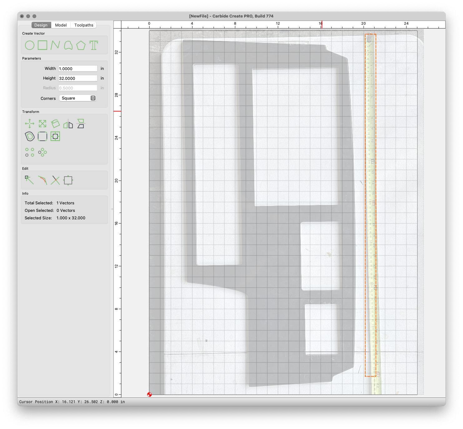
I refined Will’s method by editing the image to square it up first, and then fitting the tape measure to the grid in CC.
dashboard.c2d (44 KB)
You may need to fine tune it with better measurements.
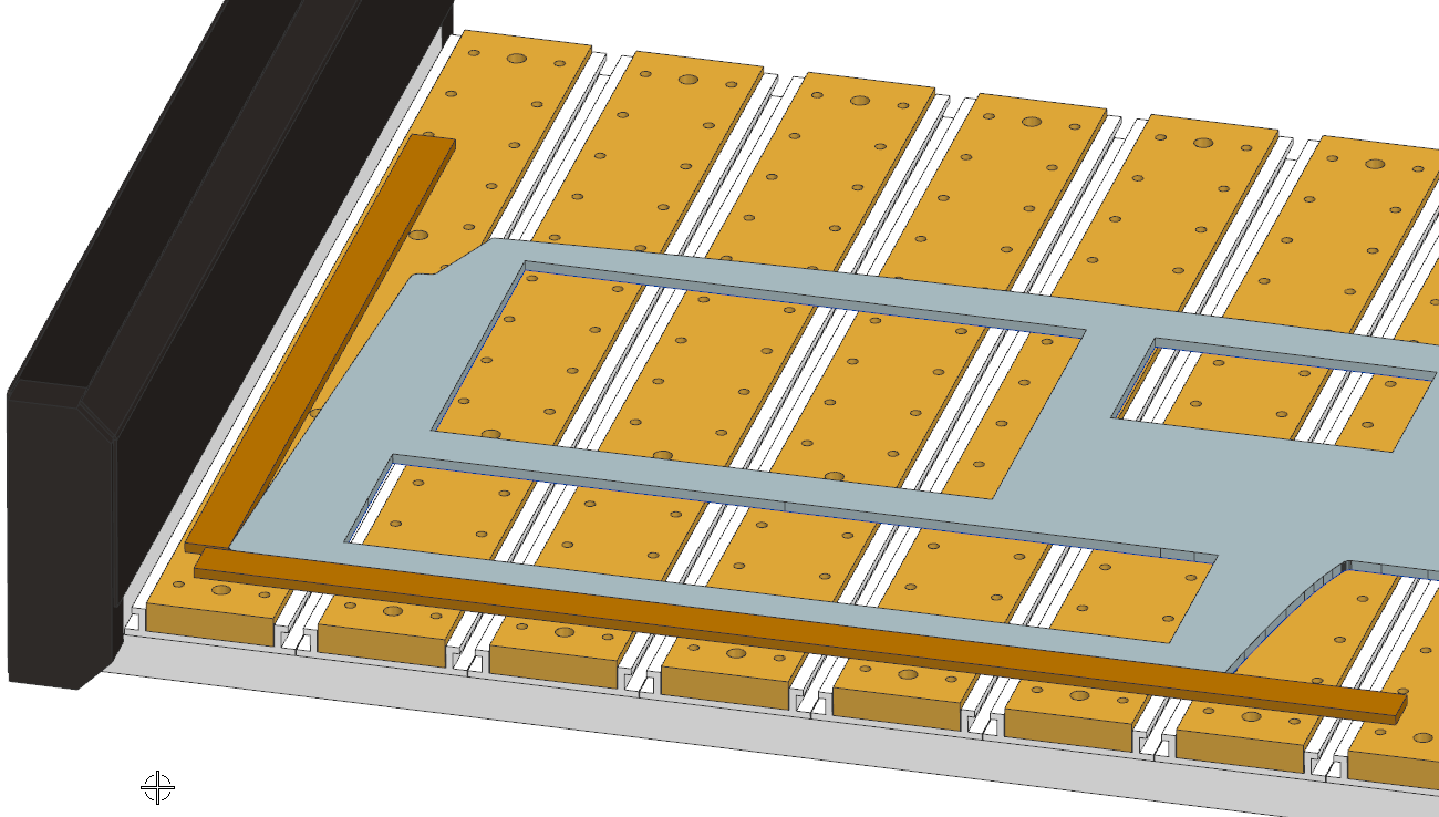
If a tape measure is the most accurate measurement device you have, try squaring it up on the machine and using a sharp V-bit to move around & pick up points.
2 Likes
How can I do that ? Also I don’t have a V-bit. This panel confuses me very much with the angles
mount a straight edge (fence) & machine it parallel to the X axis. (optionally add Y axis fence too)
Use any sharp pointed tool and jog over the lower left corner & set XY zero. Jog to all other points, like the opposite corners of each rectangle, at least 3 points on each of the curves, and the other corners of the edge & jot down the positions. Now you can use these points to construct the part in CC, or any CAD software.
2 Likes
This topic was automatically closed 30 days after the last reply. New replies are no longer allowed.