There is a six pin connector on the main board and a four pin. Can anyone identify these connectors and where they might be available?
Pinout: https://shapeokoenthusiasts.gitbook.io/shapeoko-cnc-a-to-z/anatomy-of-a-shapeoko#controller-board
6-pin: https://www.molex.com/molex/products/part-detail/pcb_receptacles/0447640603
4-pin: https://www.molex.com/molex/products/part-detail/pcb_headers/0026604040
Search the forum for “Molex” for more information.
4 Likes
Check out Digikey.com for these Molex connectors.
I know for sure the six pin is for adding the BitRunner and/or other devices that work off of a relay. The four pin I do not know but I am sure someone does.
It’s already explained in the link I posted earlier:
-
The 6-pin is primarily for PWM output (e.g. spindle control). On the Nomad this is used for the built-in spindle. I guess the more recent BitRunner uses the reserved pins.
-
The 4-pin is for auxiliary on/off and power. On the Nomad this connector is hooked up directly to the power button.
1 Like
The PCB board 2.4e has three pins marked as “Reserved” for the z-probe. I want to use my old standby, home-made probe that worked well for the older PCB 2.3 board, but it only requires two pins. Question: WHICH two of the three Reserved pins should be used (assuming the remaining pin is for ground)???
You want the same contacts as the ones on the PROBE header. The reserved header is the same thing, just with an extra pin.
Top pin of RESERVED = right pin of PROBE = GND.
Bottom pin of RESERVED = left pin of PROBE = signal.
Middle pin of RESERVED = 5V.
Or you could just use the PROBE header.
Thanks for the response, but it doesn’t clarify because there is no header on my female 2-socket connector. I guess the real question is what male pins do I use: 1 and 2, 1 and 3, or 2 and 3
Also, since the board is upside down, what pin is “top” (or “bottom”).
In other words, which pin (1 or 3) is CLOSEST to the Riser Board?
As I said, you want the same pins as used on the PROBE header, so top and bottom.
And I have no idea what orientation your board is in, so “top” and “bottom” refer to the orientation of the PCB layout, which can be easily determined by looking at the silk screen.
If you want to know which direction is up and which is down, look at the text on the silkscreen.
Absent that, “top” is the pin on the reserved header closest to the edge of the board, or the pin attached to the green wire in the first post of this thread and IIRC the edge of the board farthest from the stepper motor connectors.
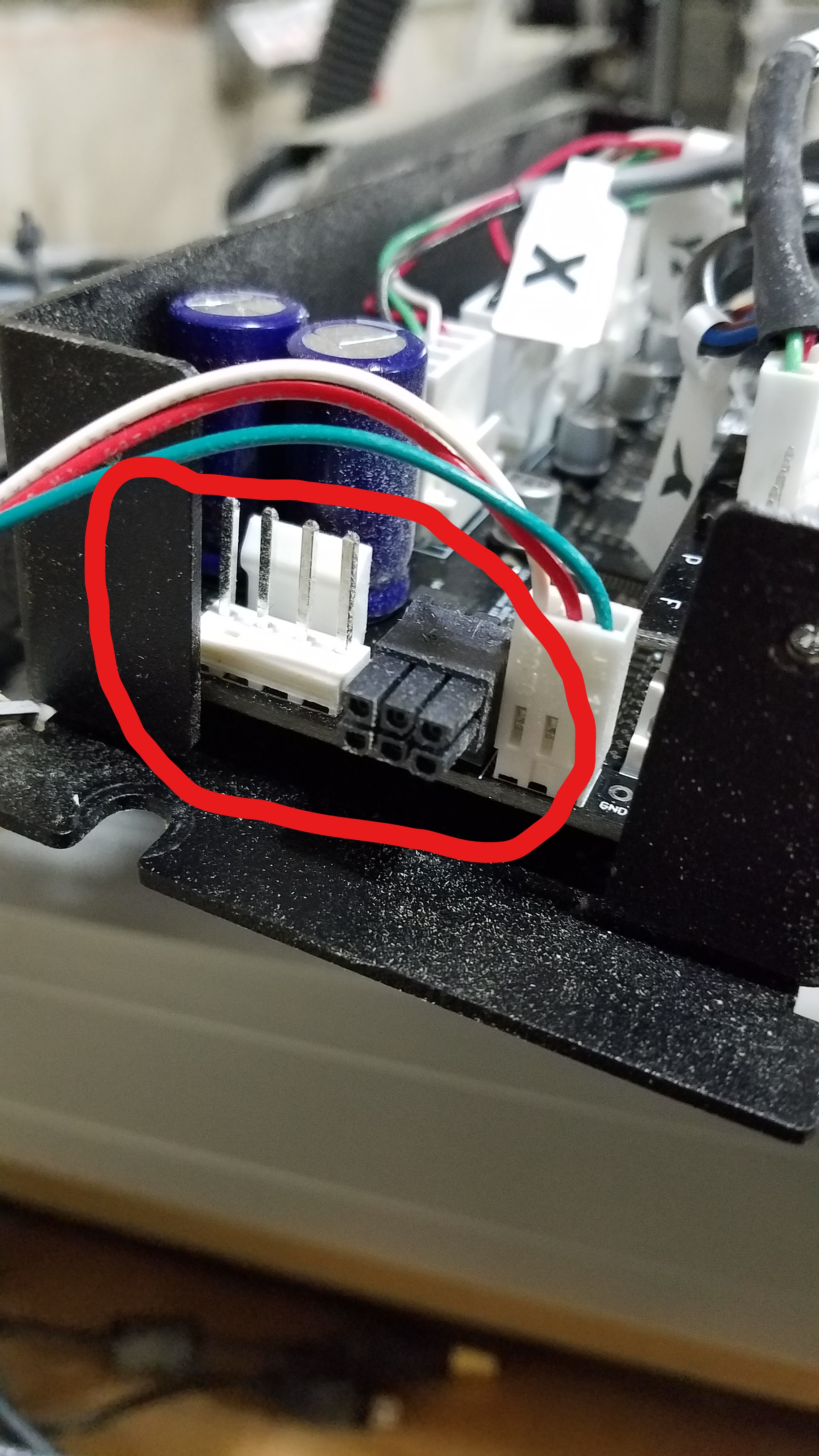
Ha ha. We’re not communicating, which would be funny if not so frustrating. Attached is a picture. On the left, clearly labelled, is the female head to the probe; it has two wires. To the right are the three pins of the Reserved area. Now that we have a common frame of reference, a picture, which pins should be used? Let’s call the pin closest to the BitRunner Connector #1.
Well, it seems the picture didn’t get uploaded. I give up.
Don’t use the middle pin.
Ah. That’s what I was looking for! Thanks.
1 Like
Ideally, this pin would go to the probe plate.
The pin closest to the riser board would ideally go to the endmill. Again, middle is unconnected.
Make sense?
Yep, perfectly. 
This topic was automatically closed 30 days after the last reply. New replies are no longer allowed.