Using 0.062, need an opening thats 2" x 5.1". Set up a tool path to cut on the inside of the vector, 0 offset, using a 1/4" single flute cutter (actual diameter is .246" which is set in in the specs for this tool) Depth of cut is .062 in 2 passes.
The first pass cuts to the proper dimensions, but the 2nd is offset inward by .06" on the bottom of the rectangle. Reran the tool path, but this time I not only got the. 06 offset, but the sides are not parallel to each other.
I have (and have to do this often) adjusted all v wheels, belt tension, trammed the router and checked the squaring of the machine. Using a mild 30 IPM feed @ 12,000 rpm. I’ve used Loctite everywhere. I’ve replaced the bearings my DWP 611.
I cannot keep the machine tight and aligned to get consistent cuts. The project requires 6 cutouts of various sizes and since the panel is powder coated it will be costly to make a mistake. AND there are 2 of them.
Want to move up to your linear X/Z unit, but I’m stuck using my SO3XL for this project. Any thoughts or comments would be greatly appreciated.
The first thing I thought of that isn’t on your list of things you checked was to look at the belt pulleys and make sure they are not slipping on the stepper shaft.
I went back and rechecked the stepper pulleys and you’re spot on. The starboard one was missing a set screw (the one for the flat) and the other one was slipping. Any idea of the set screw specifications?
I have made sure all the pulleys and belts were secure. I re-ran the tool path and adjusted the GRBL settings,( X & Y) multiple times, running the tool path after each change. I actually got to a point where everything jived. I moved the Y zero up to make a 2nd cut. Not the same dimensions as the previous. Some as much as .010 off (mostly X). I have done this at least 7 times, with different dimensions each time. VERY frustrated.
The current settings:
$100=39.100
$101=39.400
$102=39.400
X & Y have been moved between 39.0 and 40.0 but I still get unpredictable and inconsistent results. As I indicated before, I’m designing and producing tool paths in Aspire 11.5 and using UGS Platform to run the files. I’ve created the tool path, saved it with a # then recalculated the tool path and saved it with the next consecutive #. Done this 3 times. Printed out the GCode for each and find no discrepancies between them.
I’m out of ideas. Can the control board introduce errors like this?
My understanding is the boards are binary, either they work right, or they don’t work at all.
What feeds and speeds are you using?
Is the tool clean, and in good condition and sharp? (no aluminum galled on it)
If the machine is sound mechanically, it should cut as expected given tooling in good condition and feeds and speeds suited to the material being cut.
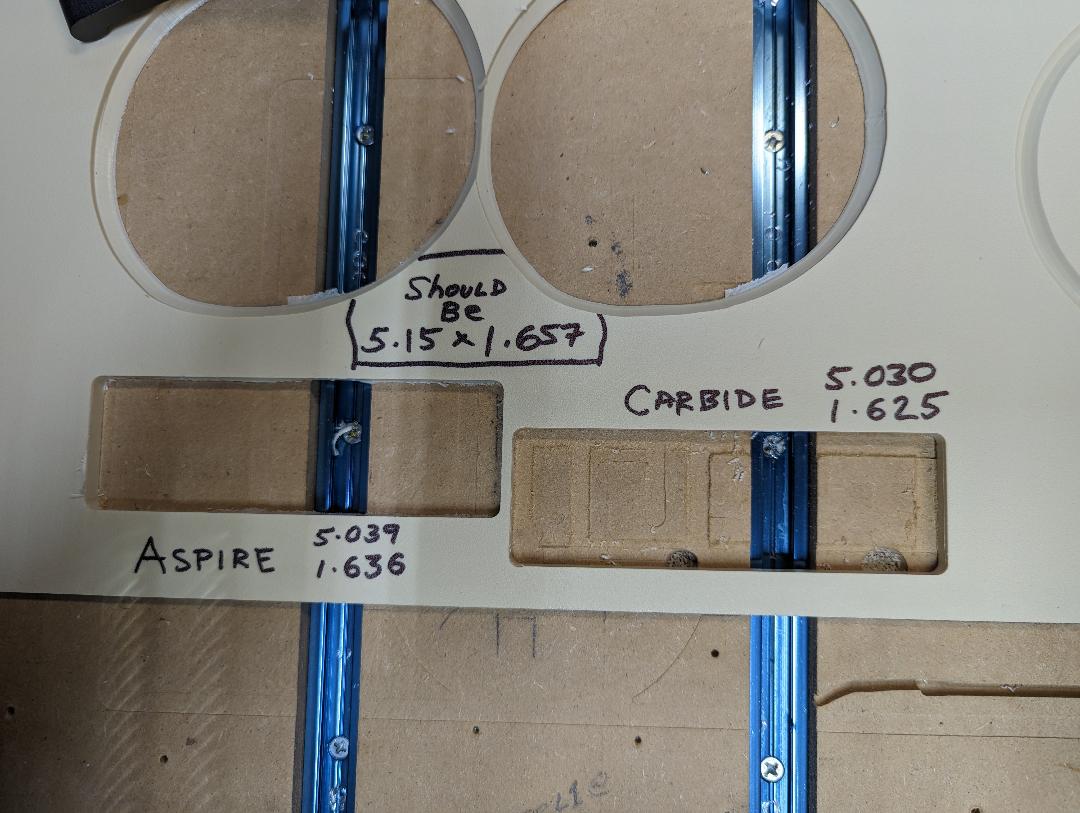
Please create a basic test file in both Vectric Aspire and Carbide Create and cut both in suitable pieces of scrap — if they both have problems, we can assist with the Carbide Create version at support@carbide3d.com — if only the Vectric version has problems you will have to check in with Vectric tech support.
I actually just finished doing that. I created a second rectangle 0.010 smaller and set 2 tool paths, one for each vector. I also decreased the $100 to 39.000. Helped. I’m going to change that again and recut over what I just cut.
Will, this is getting crazy. I adjusted, after calibrating, the $100 which was the only one showing out of spec. I did another cut and it came out perfect.
I moved the machine X & Y over for a clean cut and re zeroed both, leaving the Z alone. Ran the cut. Did not duplicate the cut next to it at all. It came out 0.207 (X) smaller! Y was .01 smaller. How is this possible?