The preview window will always make the drawing look worse in LightBurn.
They don’t have an option to enter in a value, only “Hide backlash” on or off.
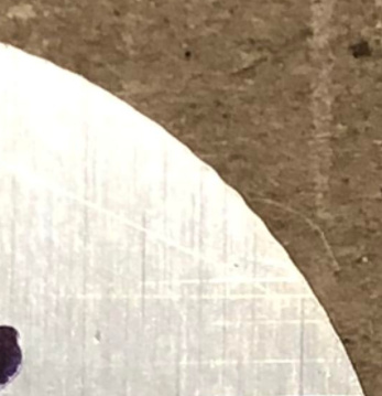
Stacking the circles on top of each other, they’re the same.
Ah… I see.
I was comparing this:
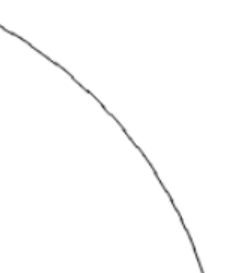
and this:
Is there anyway to draw a circle with a different bit of software?
Or, can you run lightburn on a bit of wood and run it really slowly with low power on the laser… in other words, first be 100% sure the shape you are making is a valid shape?
We’ve drawn a 50mm ø circle in Fusion as a DXF export as well as LightBurn itself (which they recommend). No difference on the output regardless of where the circle is drawn.
Does everything always go through LightBurn? There’re a lot of results mentioning circle issues and LightBurn.
2 Likes
Has hand-coding the G-Code for a circle using G2/G3 arcs been considered here?
1 Like
His laser controller doesn’t take gcode.

1 Like
Yeah that was mentioned a few times 
Understood. At least for that part of the circle, you are emulating the wobbly image perfectly 
Anybody have a recommendation for a cheap, in-stock USA 32 bit (or would 8 bits be enough?) GRBL controller just to rule out if the Chinese controller is actually the culprit? Obviously the GRBL controller won’t interface with the laser head and fiber source, but we can put a Sharpie on the carriage at least and draw a circle.
The Gradus M1 Pro from Panucatt isn’t cheap, but seems well-regarded:
Just connect an Arduino UNO to your stepper drivers.
No need to mess with anything else.
1 Like
Any wiring diagram and code and what we’re trying to diagnose? Last time I did a pulse counter project in Arduino, it ate up more time than expected and had to do low level code I wasn’t planning on.
This is assuming that the pulses that the X and Y drivers receive should be equal to make a 360º circle with the lead-in cut option disabled. Basically, the Arduino would be connected to the PUL output of the DSP controller to confirm it’s sending the pulses and not missing some.
Just install grbl. Generate gcode for a circle and run it.
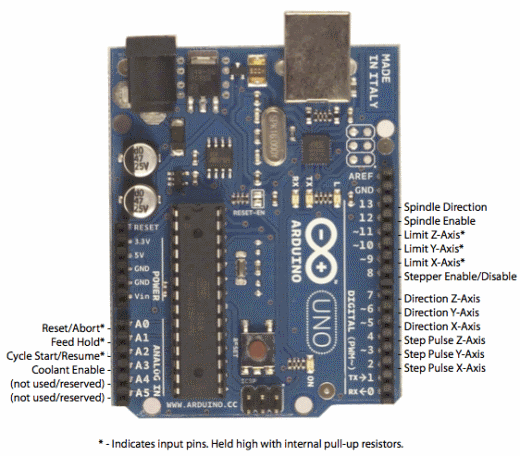
Connect step and direction pins to your drivers. No need for anything else.
3 Likes
I think it would be less wiring to undo by just counting the pulses coming from the DSP for X and Y axes 
You can just use jumper wires to the driver screw terminals, so eight screws (six of you don’t worry about the Z). PSU would stay the same. No reason for limit switches or anything else.
Since I have two Y drivers, can I substitute the Z port for Y2?
Just send the Y signal to two drivers. You can even use a breadboard.
Thank you!
1 Like
I’m down to temporarily ship you back the pro controller if that would help! I haven’t had the time to do any projects with it yet.
2 Likes