I thought I would share a part I made this weekend on the Nomad.

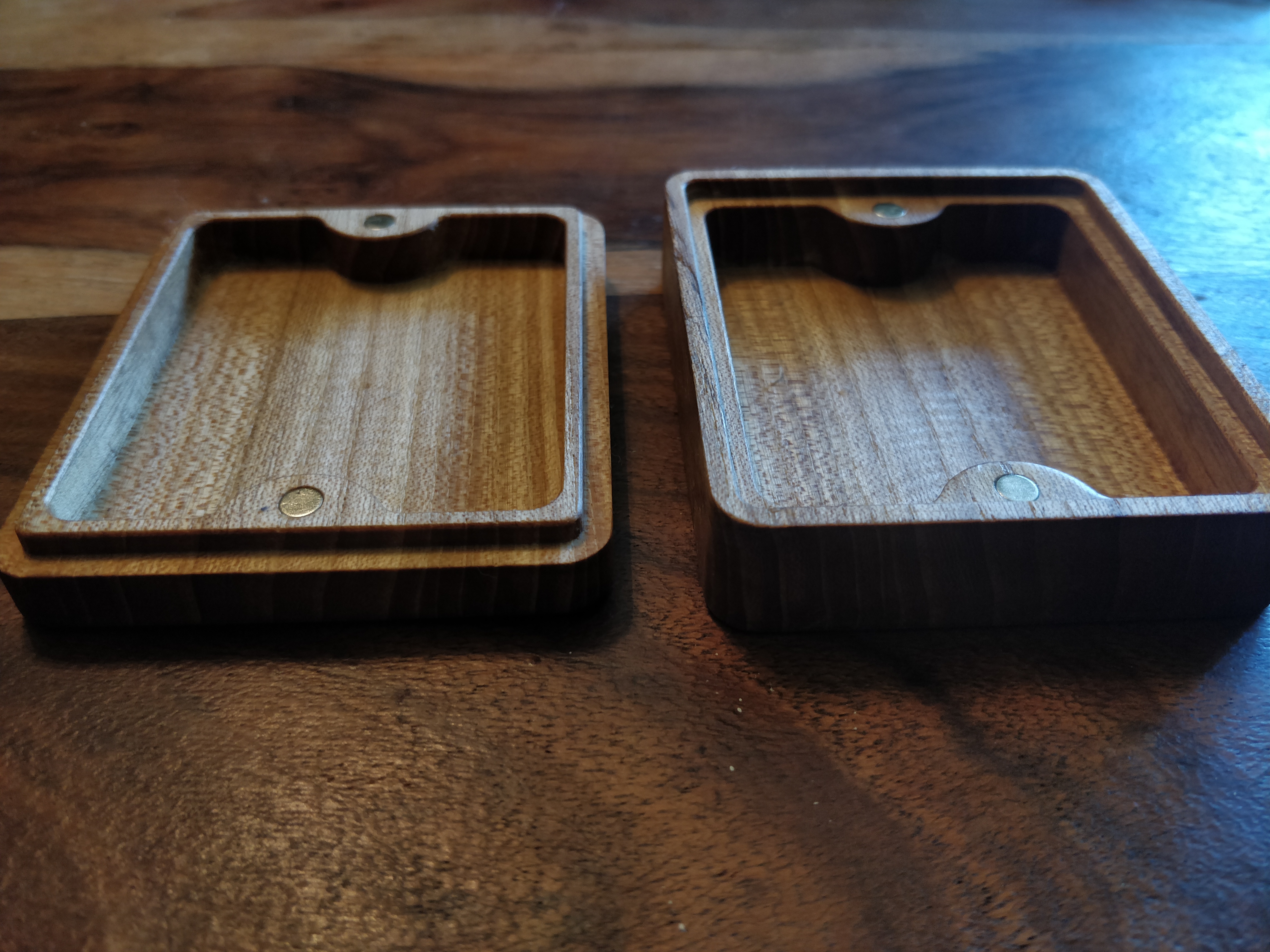
I got inspired by Winstons video on a wooden jewelry box with magnets (https://www.youtube.com/watch?v=2c6T3NjG20M&t=345s). I noticed quite a few users have made similar boxes but thought I would share mine anyway. I made a parametric box design in Fusion 360 inspired by Winstons design and machined a small tree of life in brass and glued it into the top of the part. As I wanted to chamfer the bottom and top edges of the lid and also machine a pocket for the brass part it turned into a 2 sided machining project. I flipped the stock and relocated it using 4 mm dowel pins by first machining 4.05 holes into the stock and then machining 4.05 mm holes 4 mm into the table after removing the stock to be able to relocate the part using the dowel pins. But if someone does not want to do that it is readily machined in one setup.
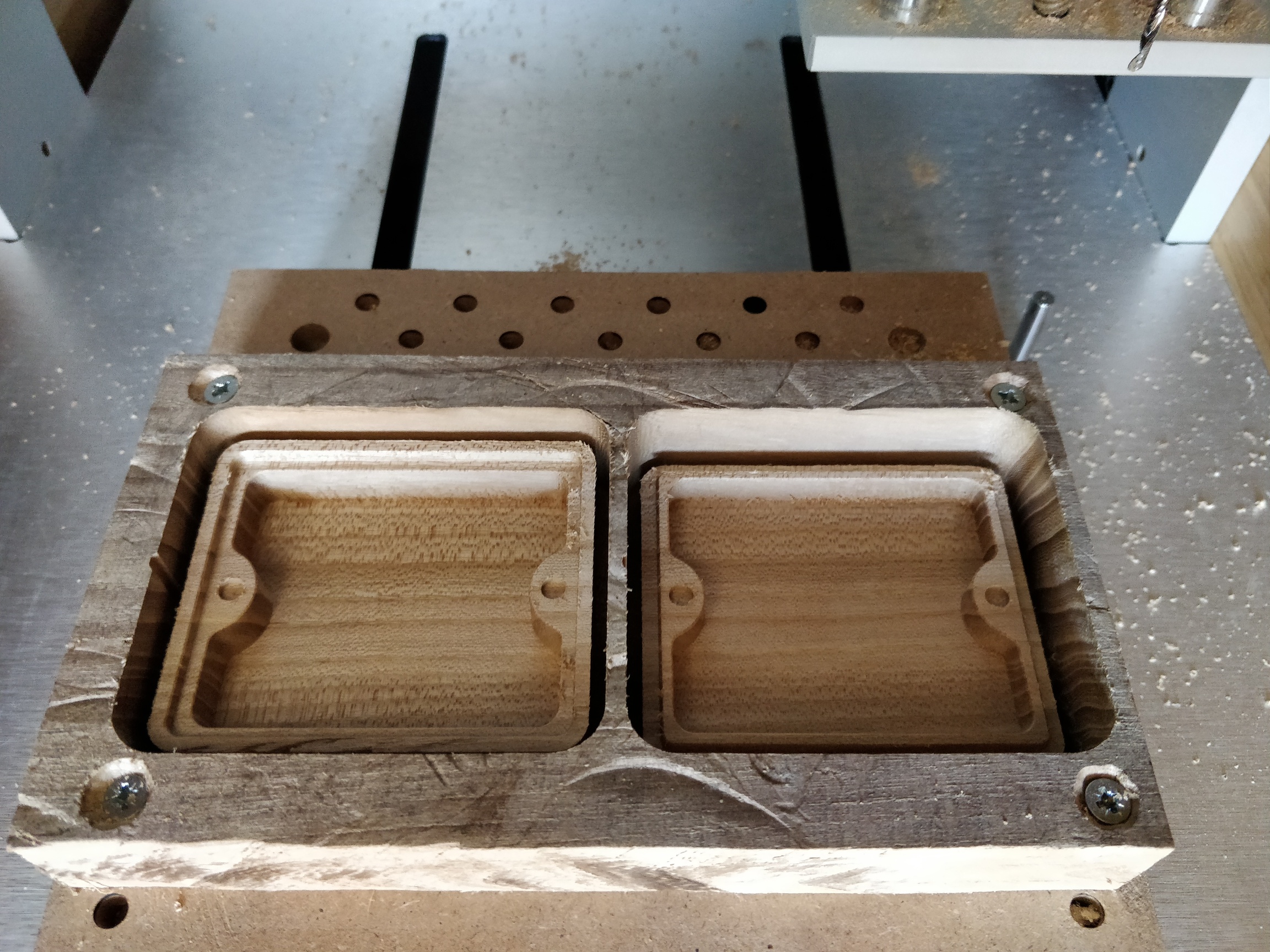
I inserted 5 mm magnets into the part, mindful to orient the magnets in the right direction as a previous box turned into a box impossible to close as the magnets would push the lid off haha…
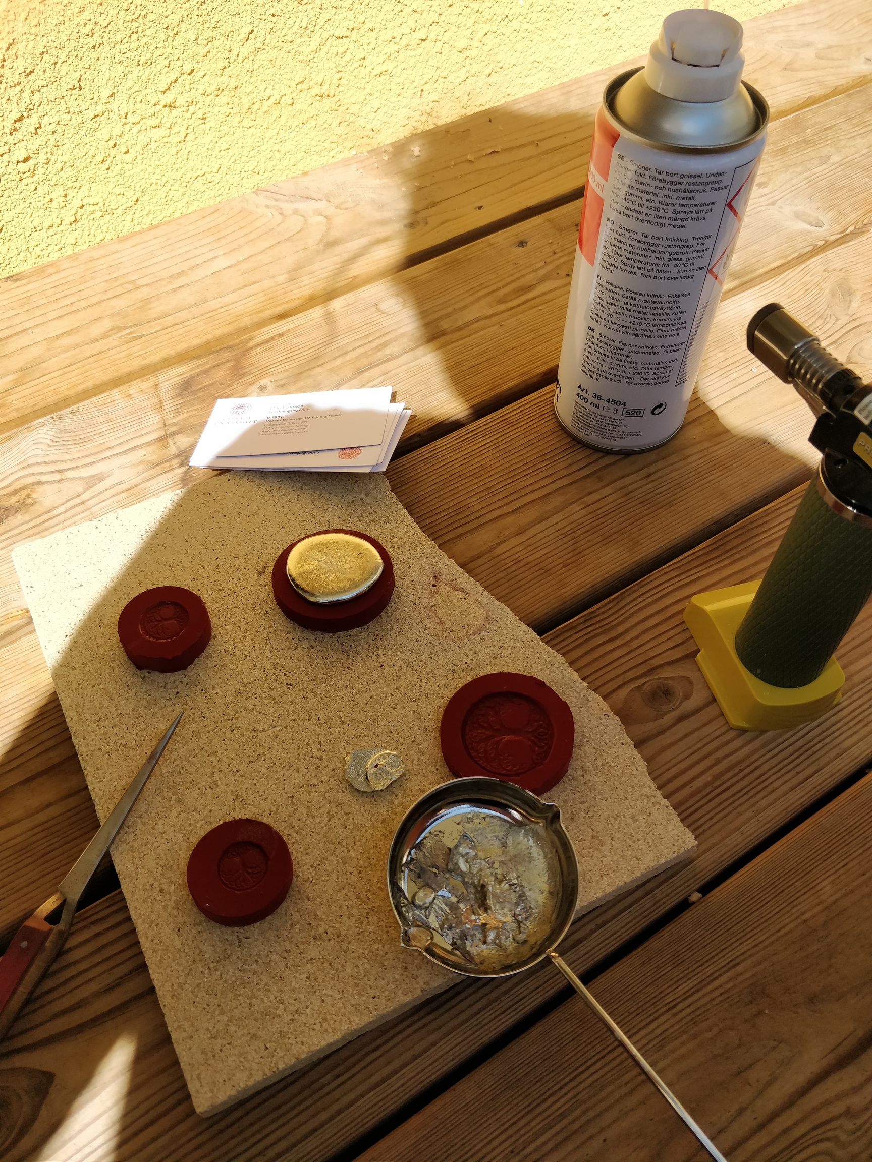
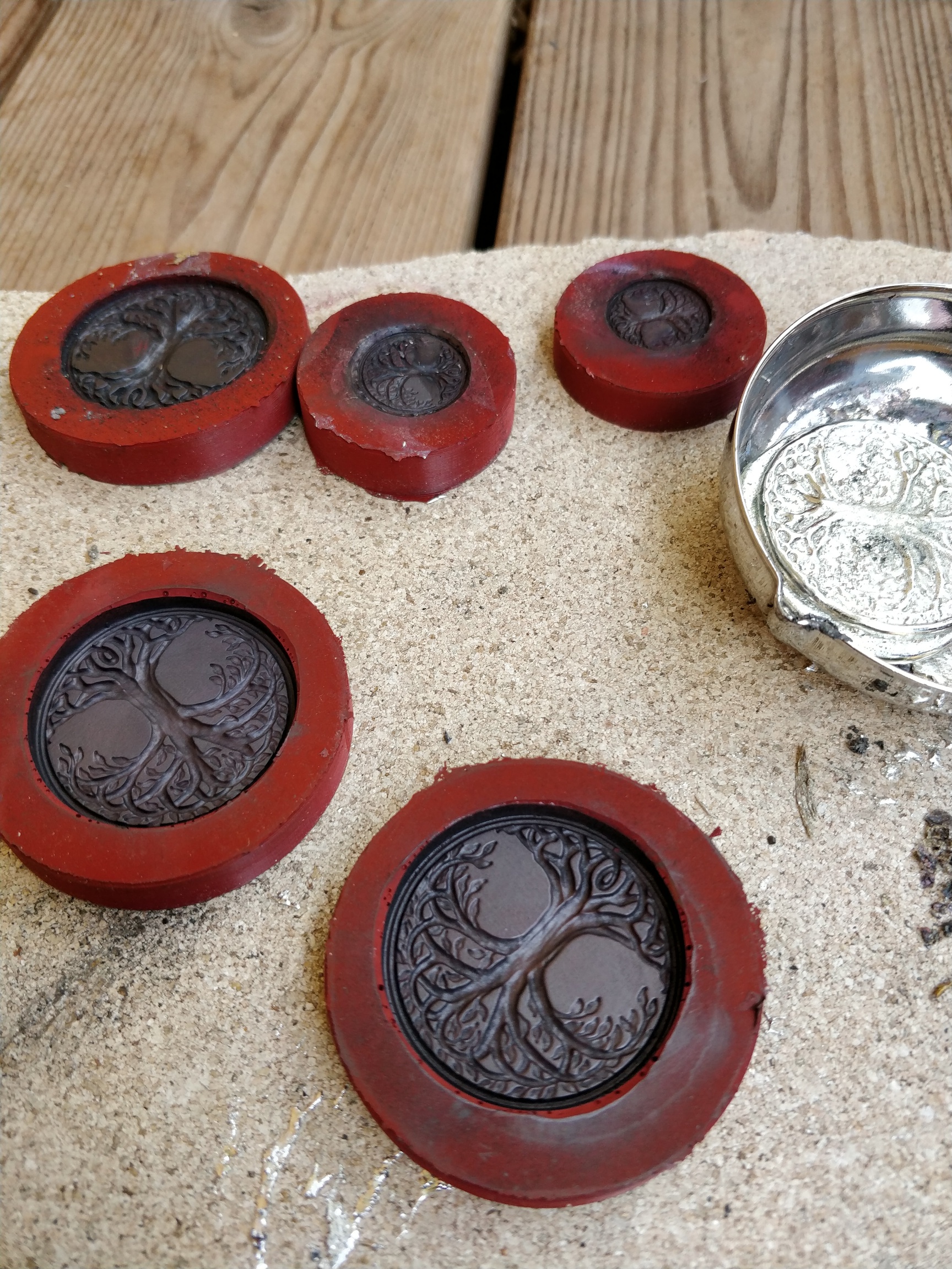
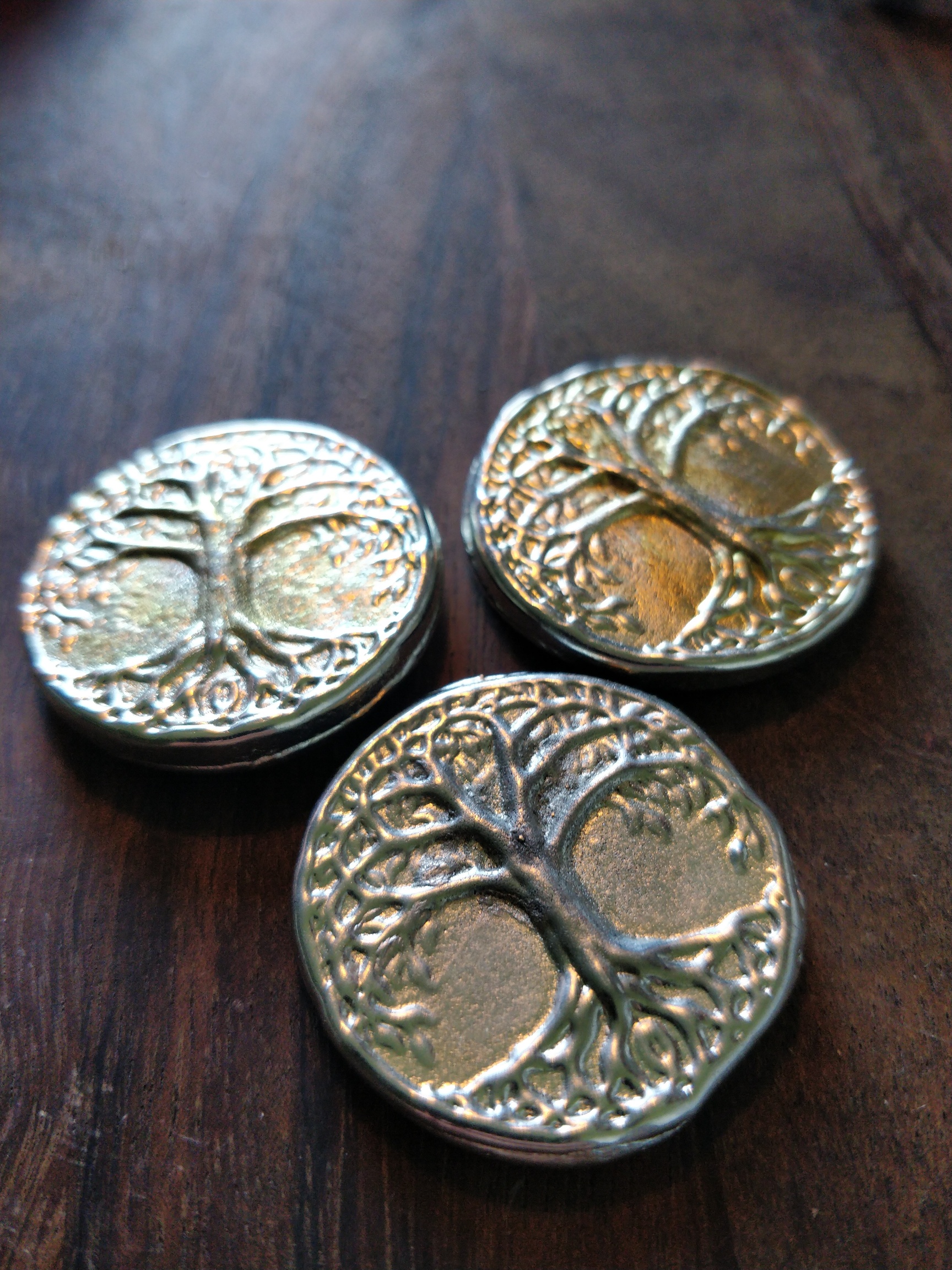
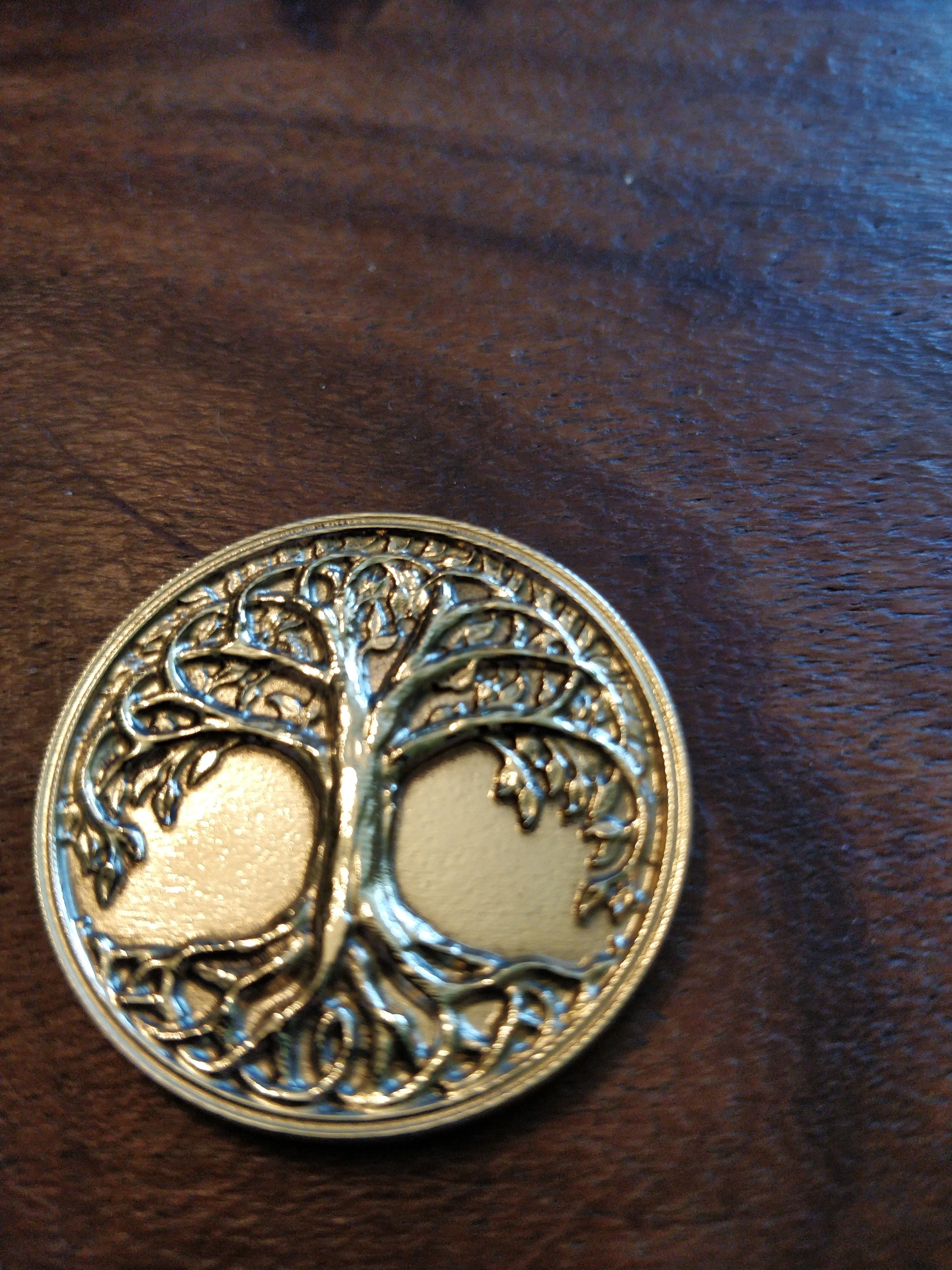
I machined the tree of life design from 3 mm brass stock using a 2 mm flat end mill and then a 2.5 mm ball end mill followed by finishing with a 1 mm ball end mill. (I tried getting even more detail with a 0.4 mm ball end mill that broke halfway through finishing).

As one cannot add depth of cut with parallel toolpath in fusion I used stock to leave to make sure I did not brake the 1 mm end mill and closed in on the nominal dimensions fairly slowly with successive toolpaths with less stock to leave. This is a bit time consuming, is there a better way to do this?
I bought the tree of life design online and can therefore unfortunately not share it. But if someone wants to purchase it, this is where I got it: https://www.cgtrader.com/3d-print-models/art/sculptures/tree-of-life-printable
I polished the brass part with a dremmel tool before gluing it into the lid.


Here is a link if anyone want to download the fusion 360 file for the box https://a360.co/31dXhsv. The design can be changed by parameters which can be found under the modify tab -> change parameters.
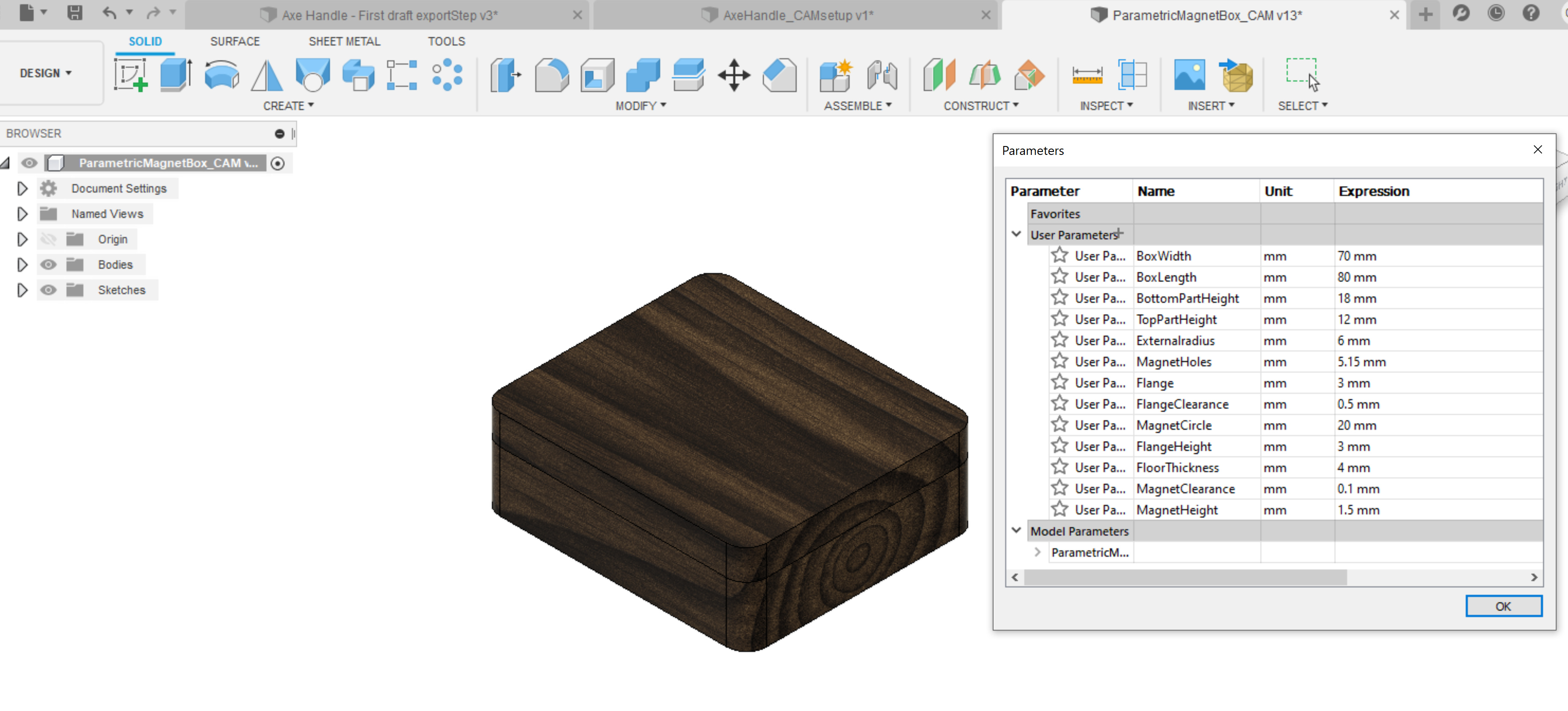
By changing BoxWidth, BoxLength, BottomPartHeight, TopPartHeight you can change the box dimensions and the design will update by itself. If anyone is interested in using the model feel free to use it for any purpose! Also, the MagnetHole and MagnetHeight parameters govern the holes for the magnets and can be changed to accomodate other magnets but I would not put much larger magnets into the part as it would probably be difficult to open.