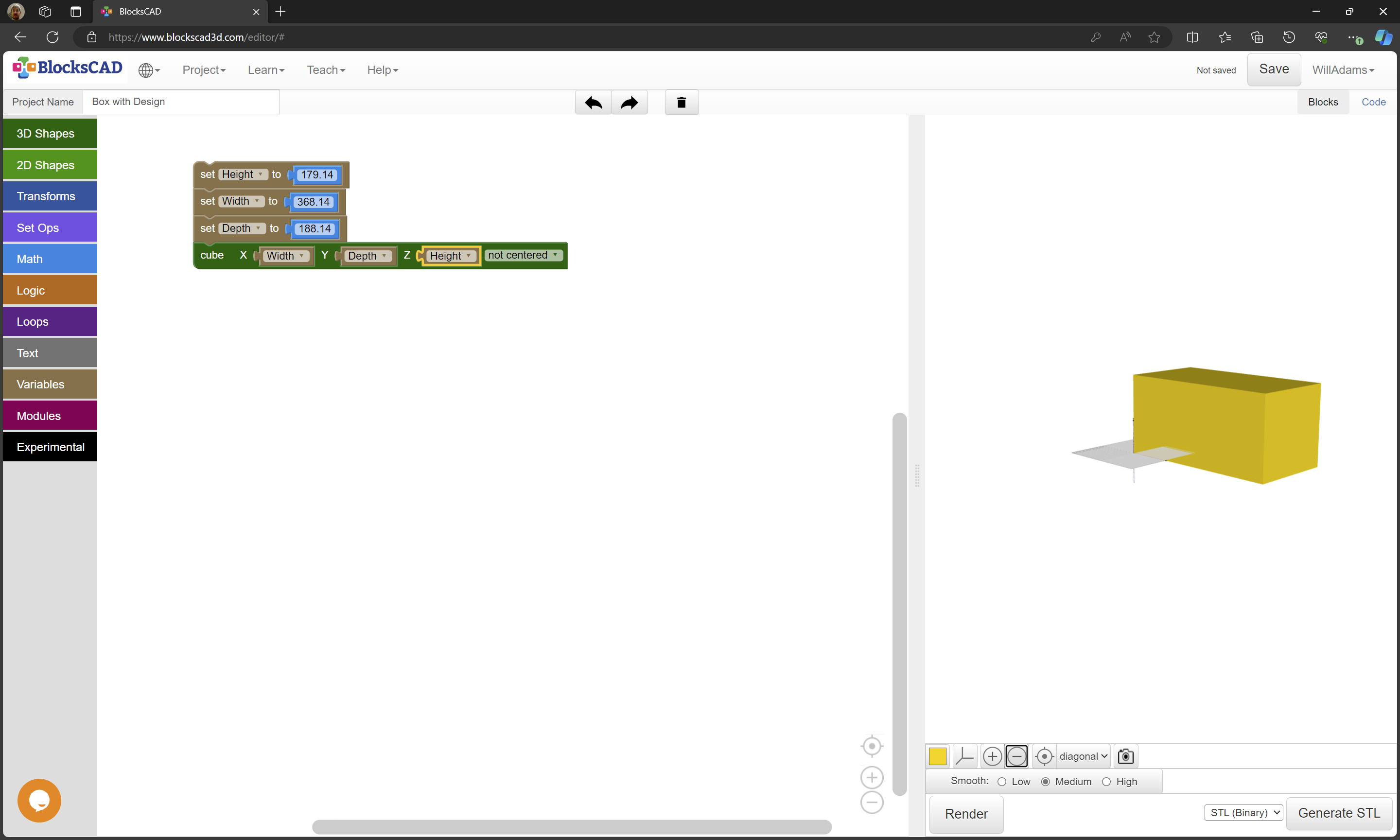
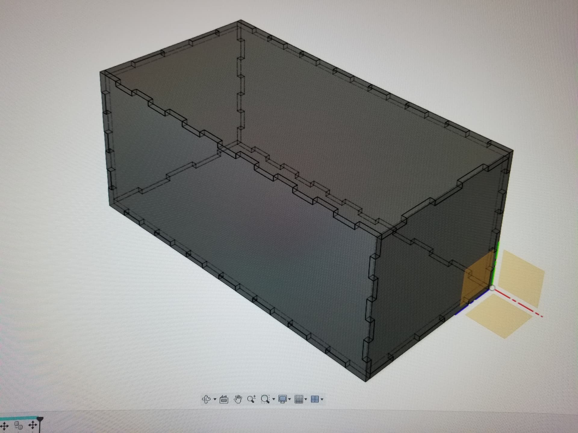
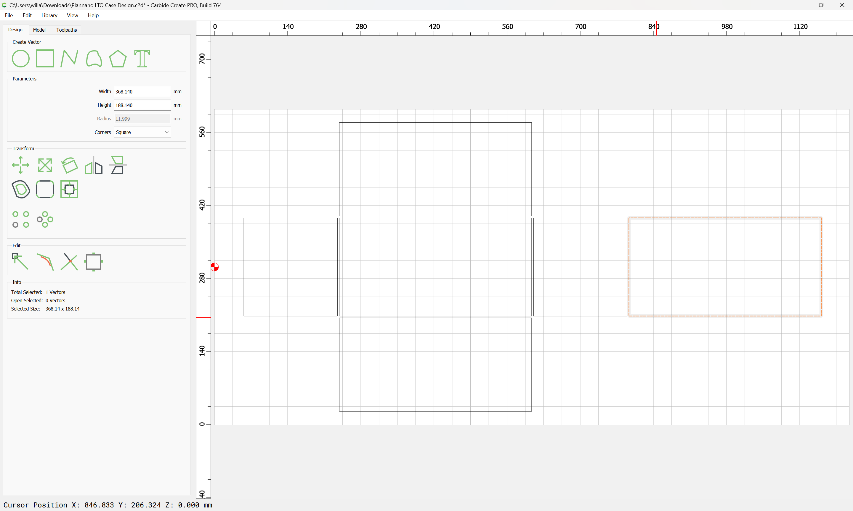
Height: 179.14mm x 188.14mm(ends/sides)
Width: 188.14mm x 368.14mm(top & bottom)
Length: 368.14mm x 179.14mm(front & back)
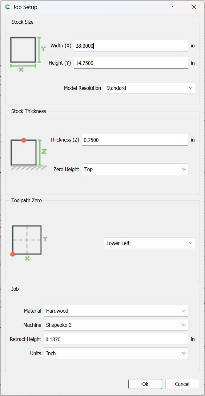
cut from a piece of stock:
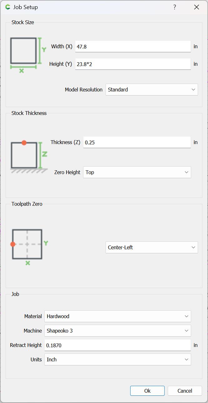
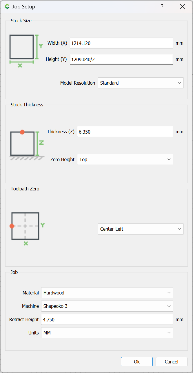
Stock size is 47.8 x 23.8 x .25 inches
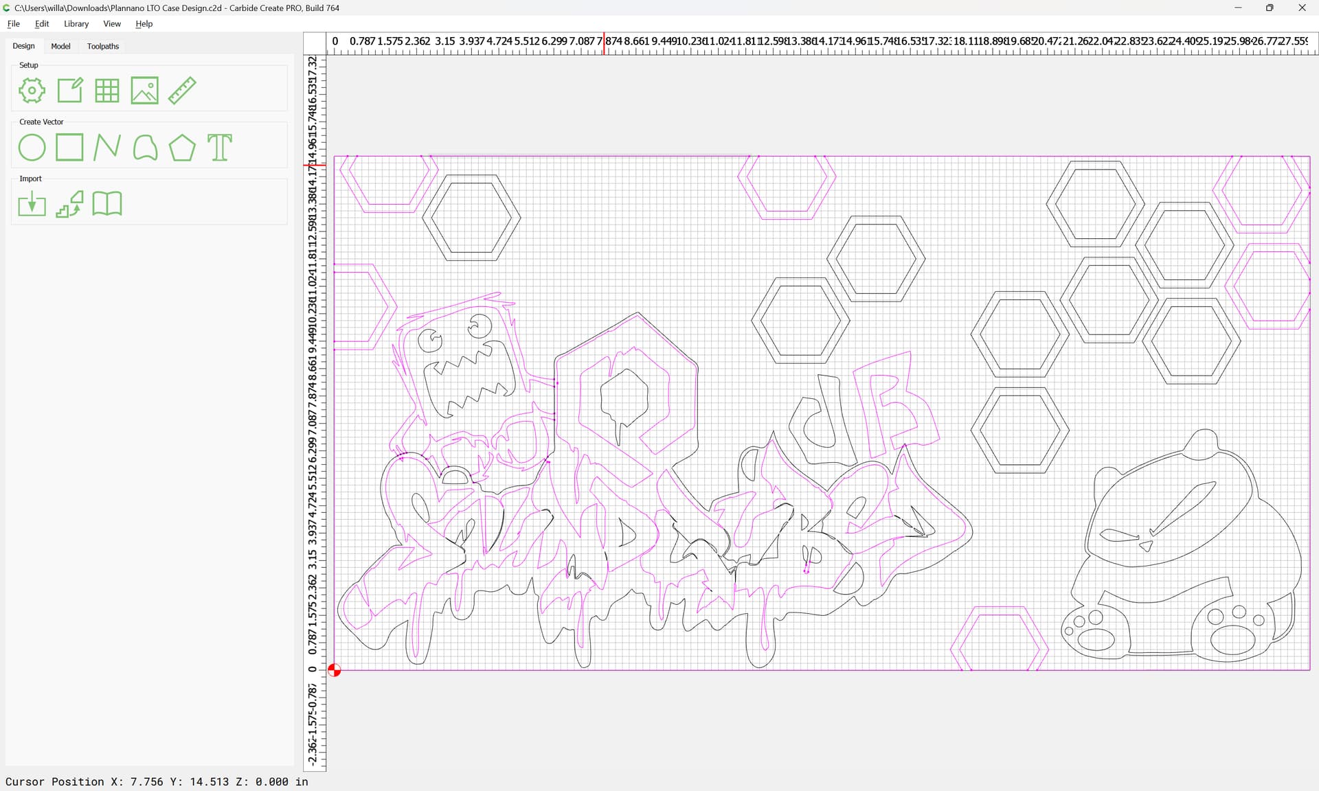
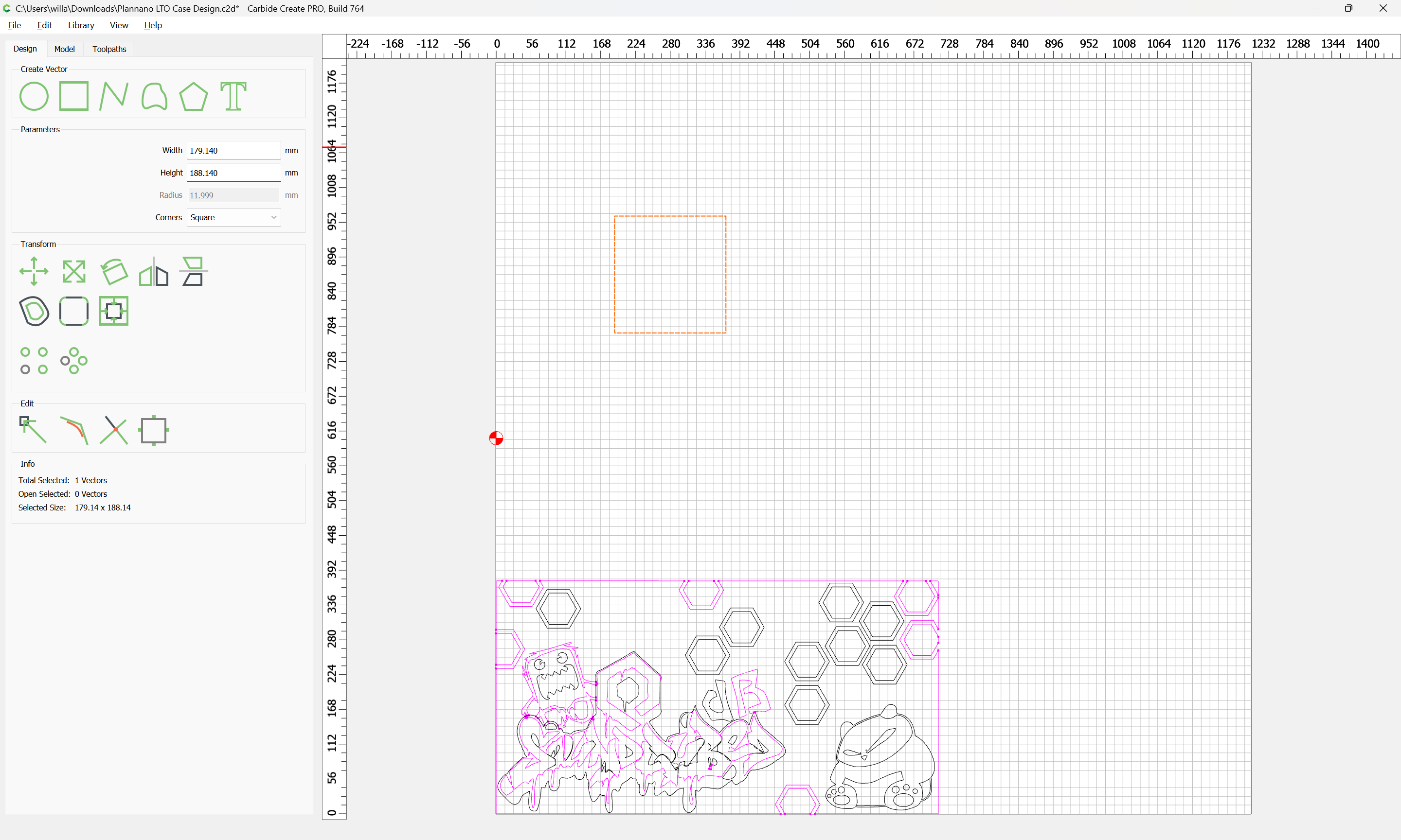
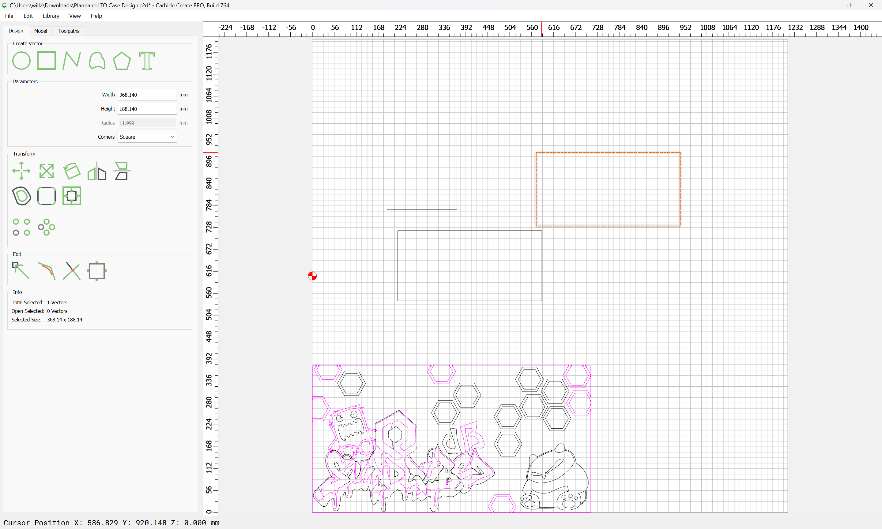
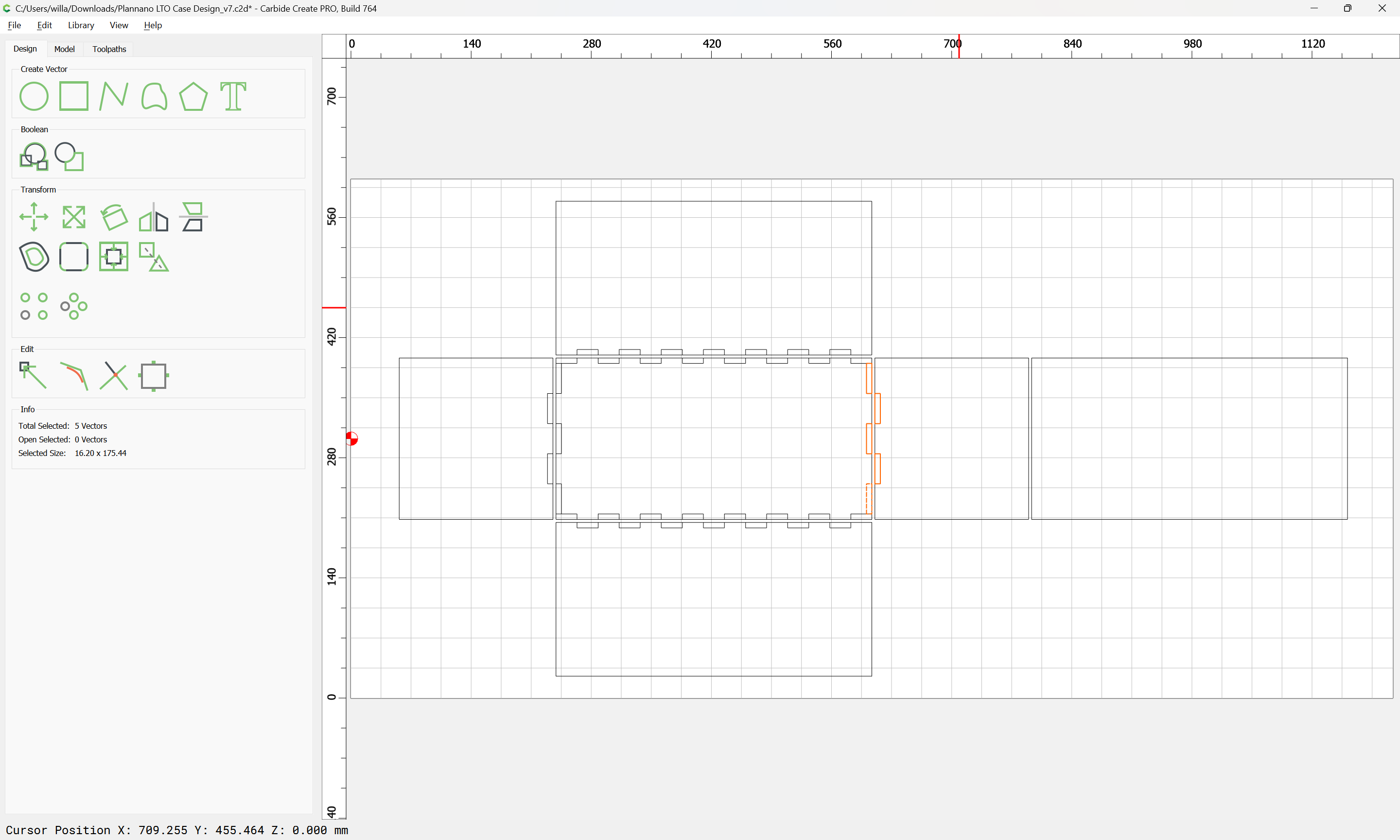
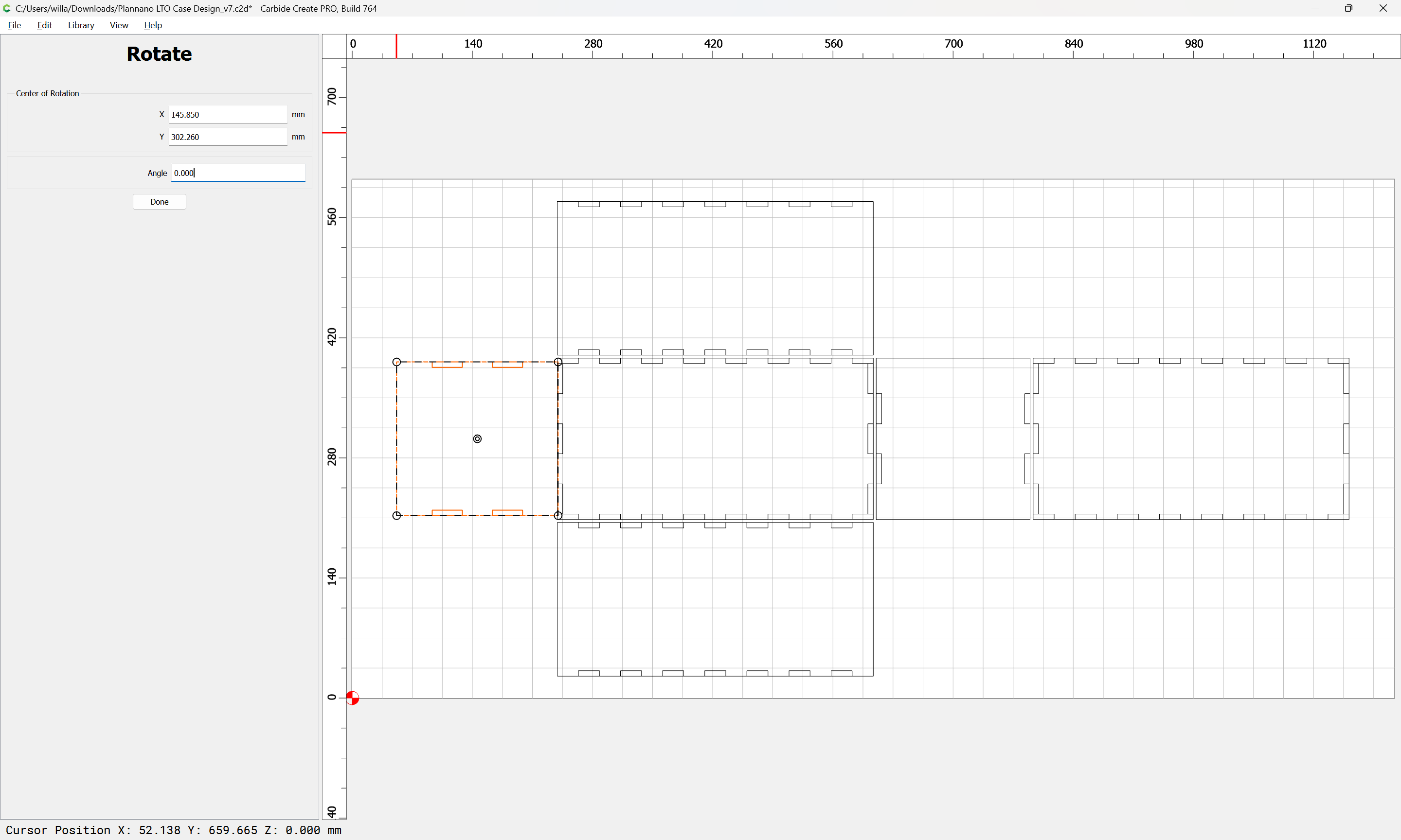
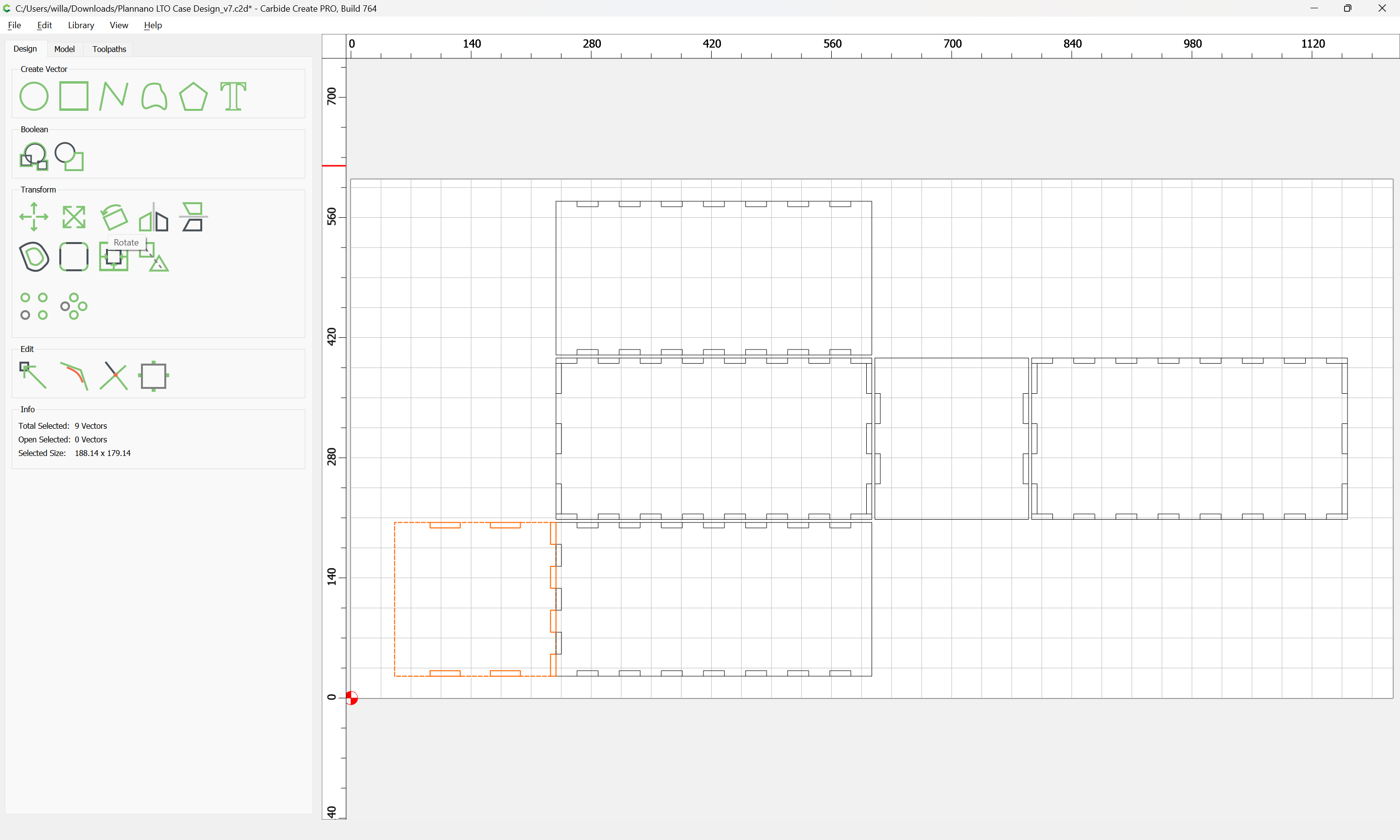
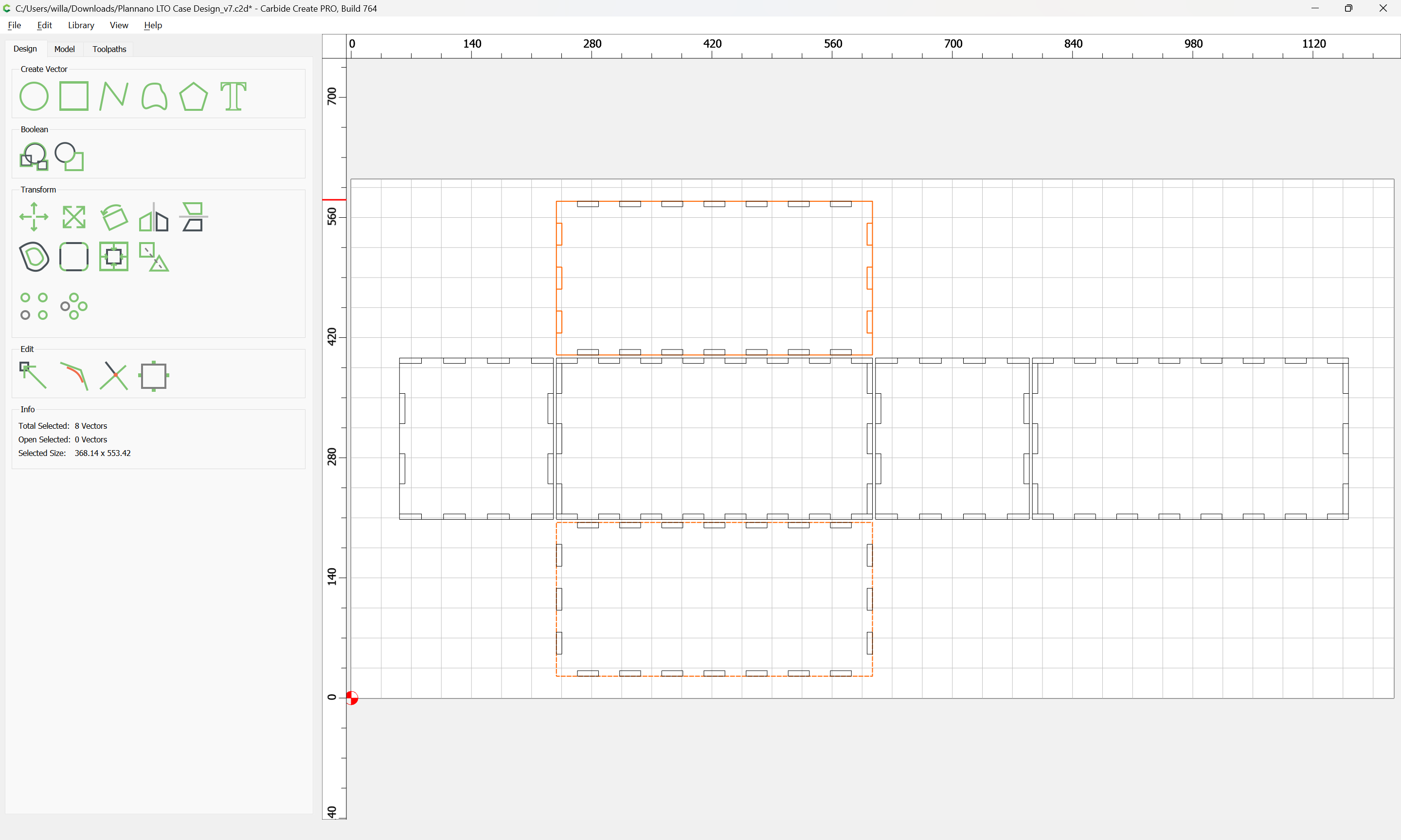
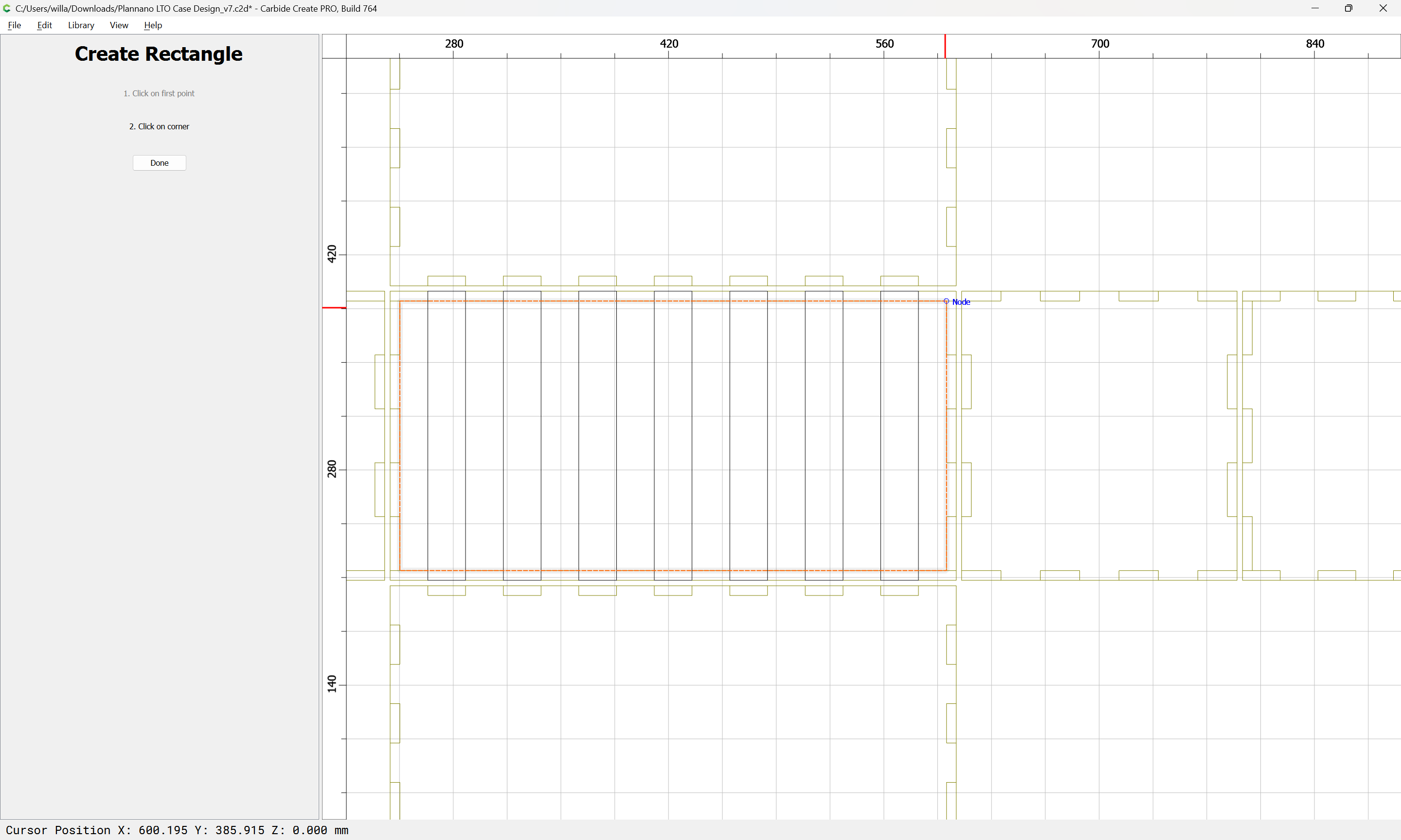
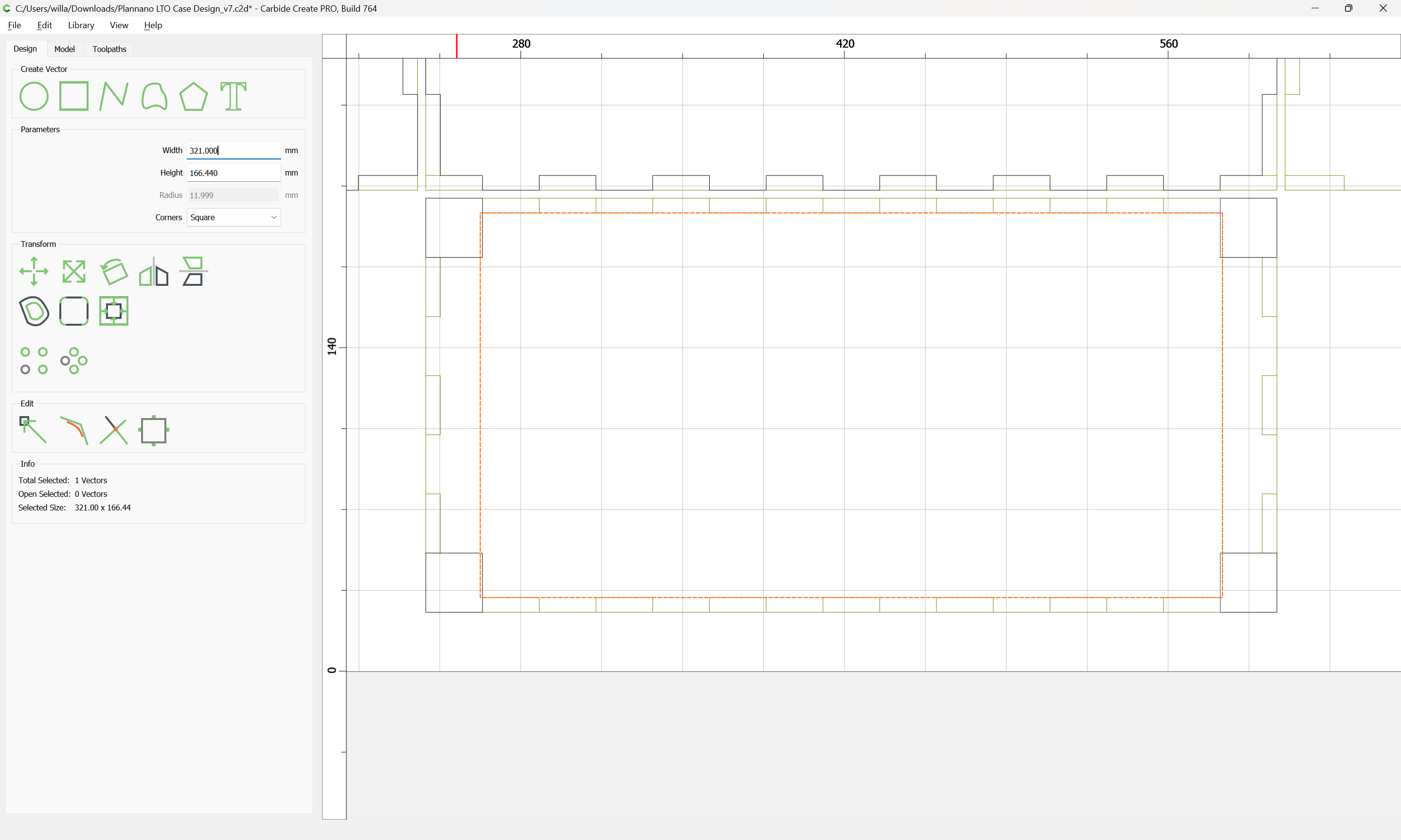
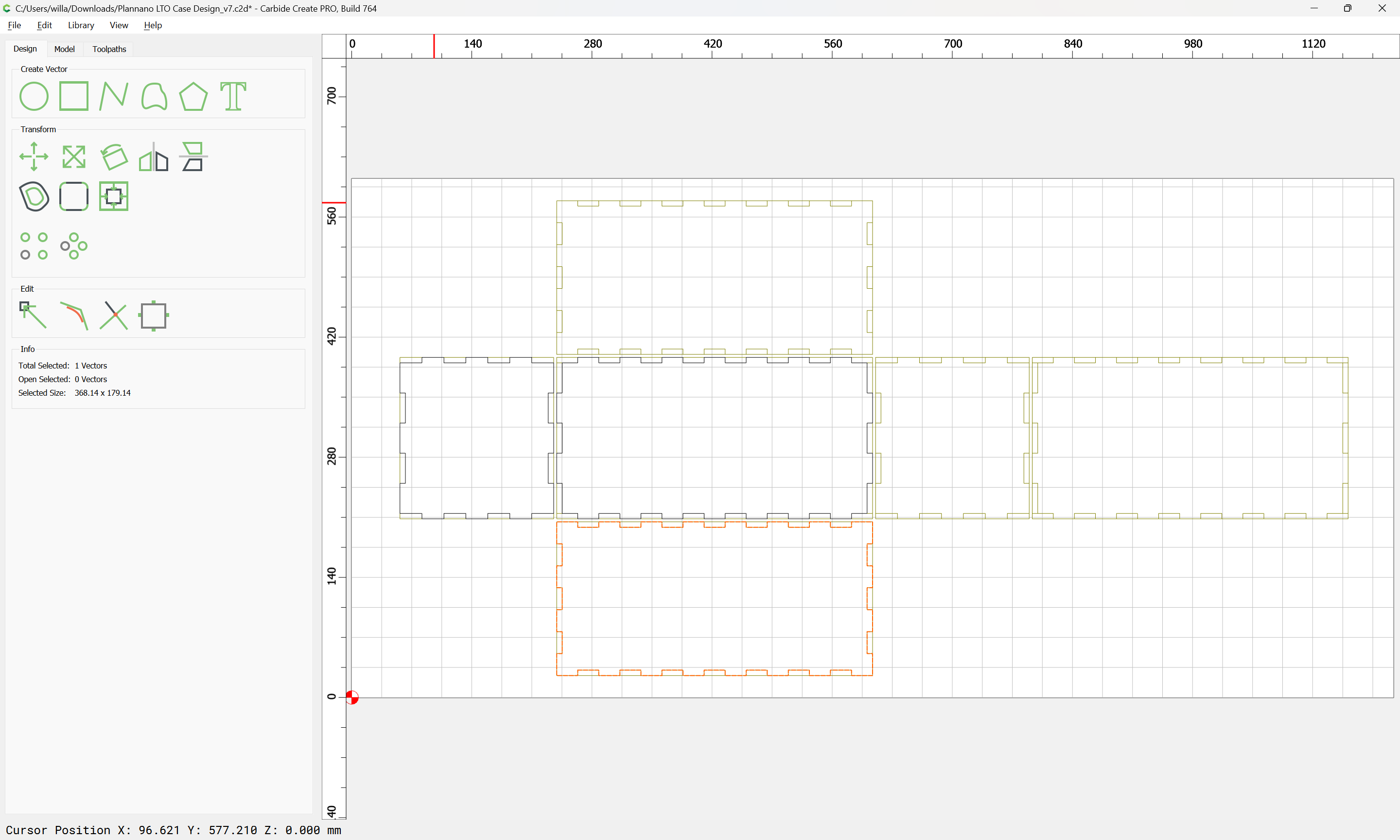
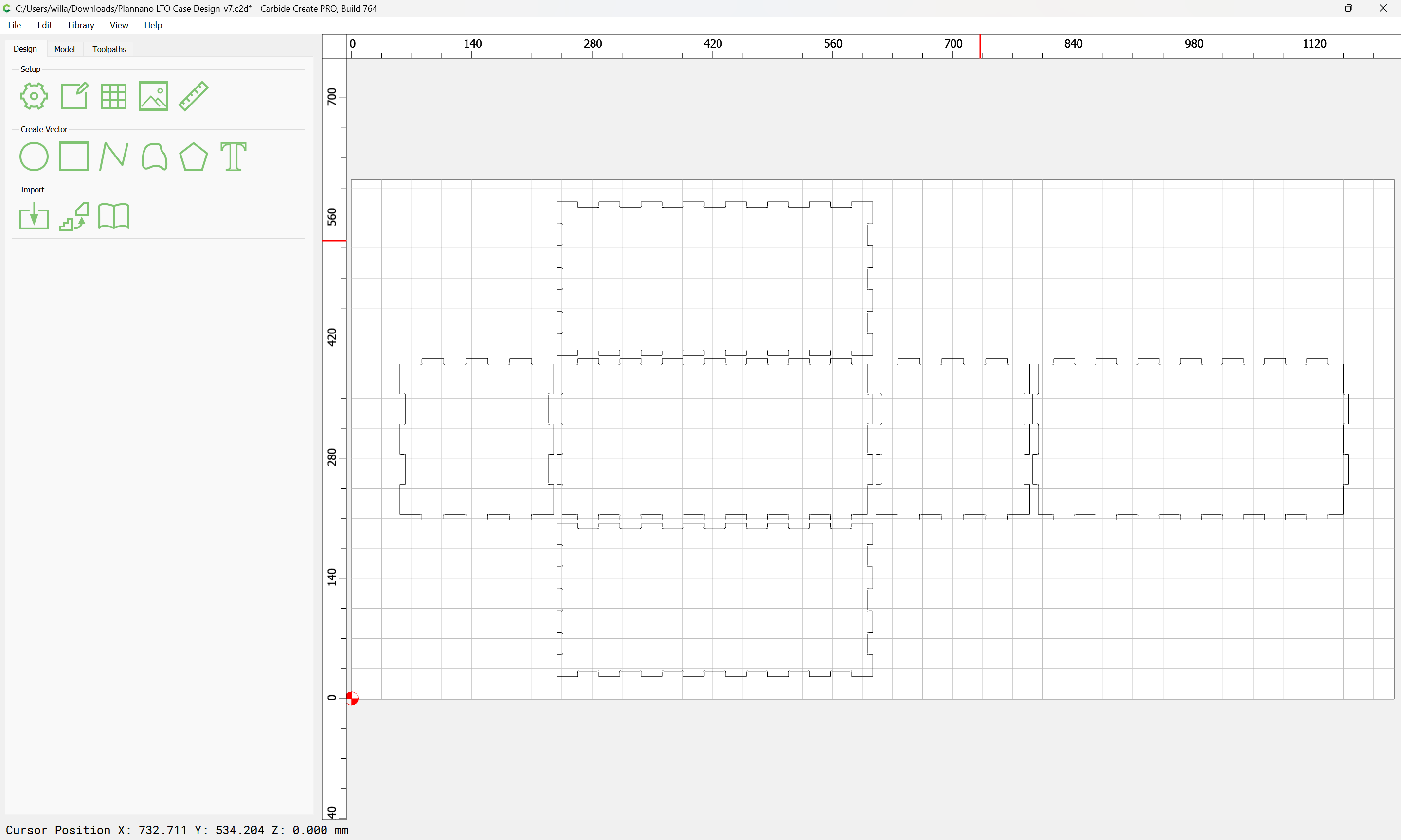
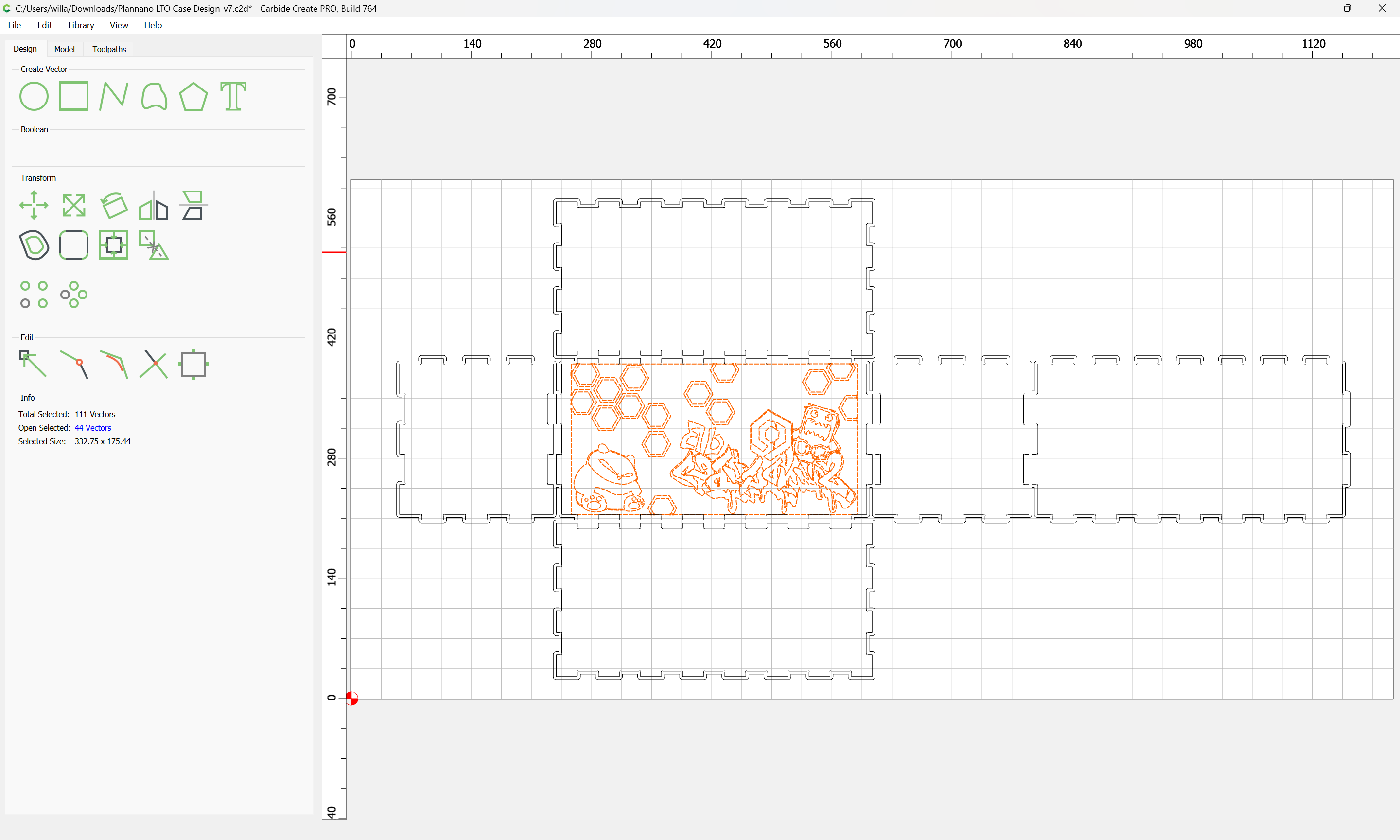
this would need to be set up as a two-sided job — so as to keep things simpler, we will use Center Left for the origin and arrange things so that top/bottom of the file will map to front/back of the stock:
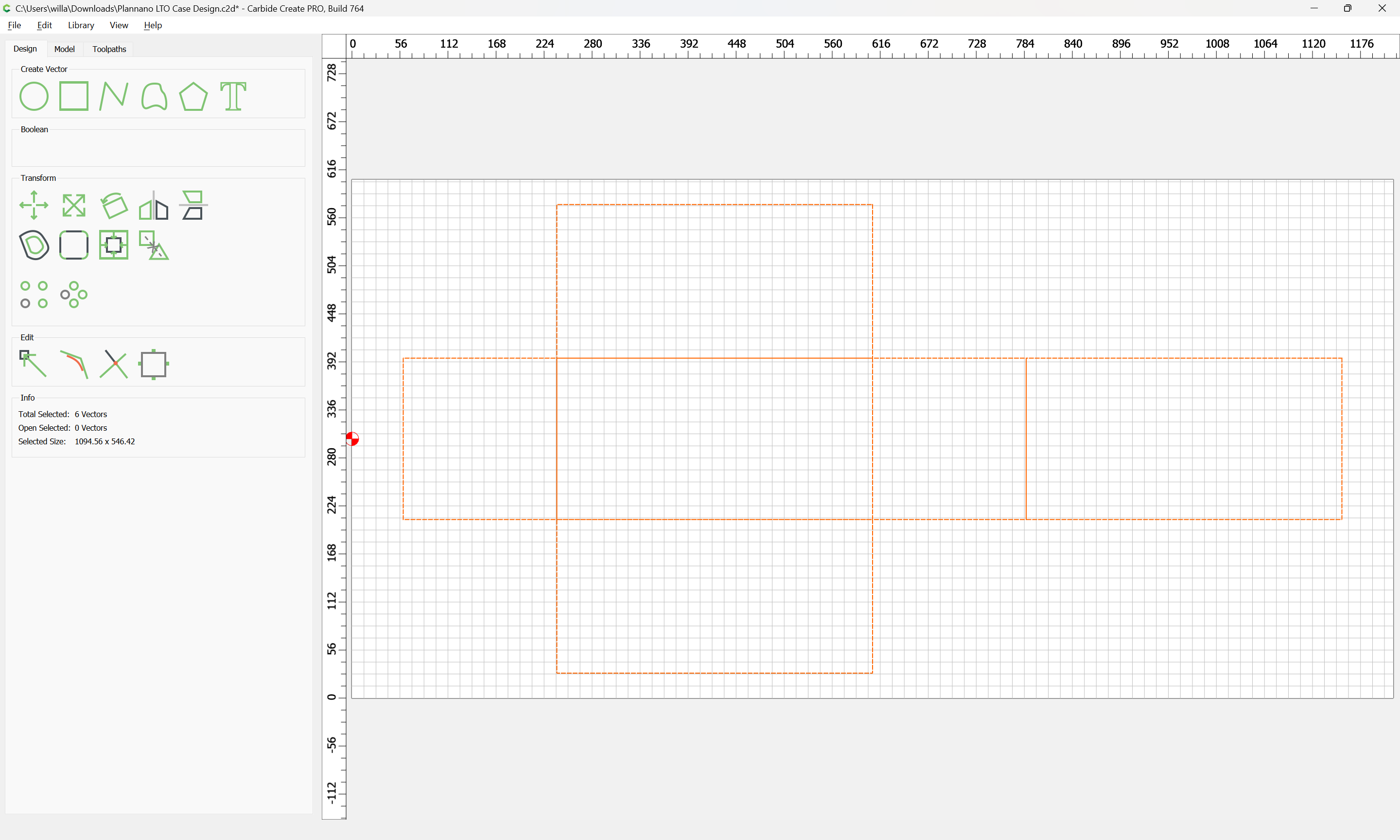
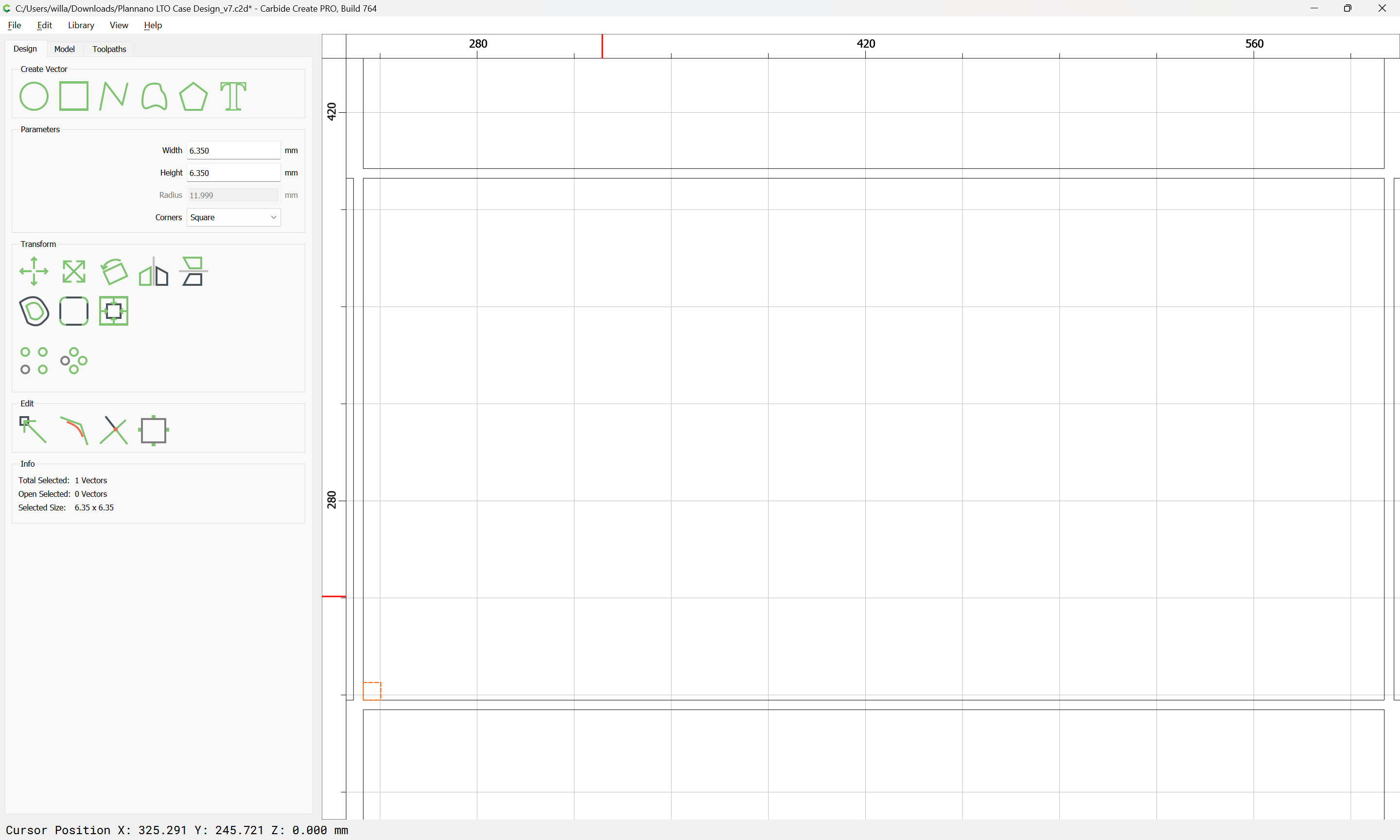
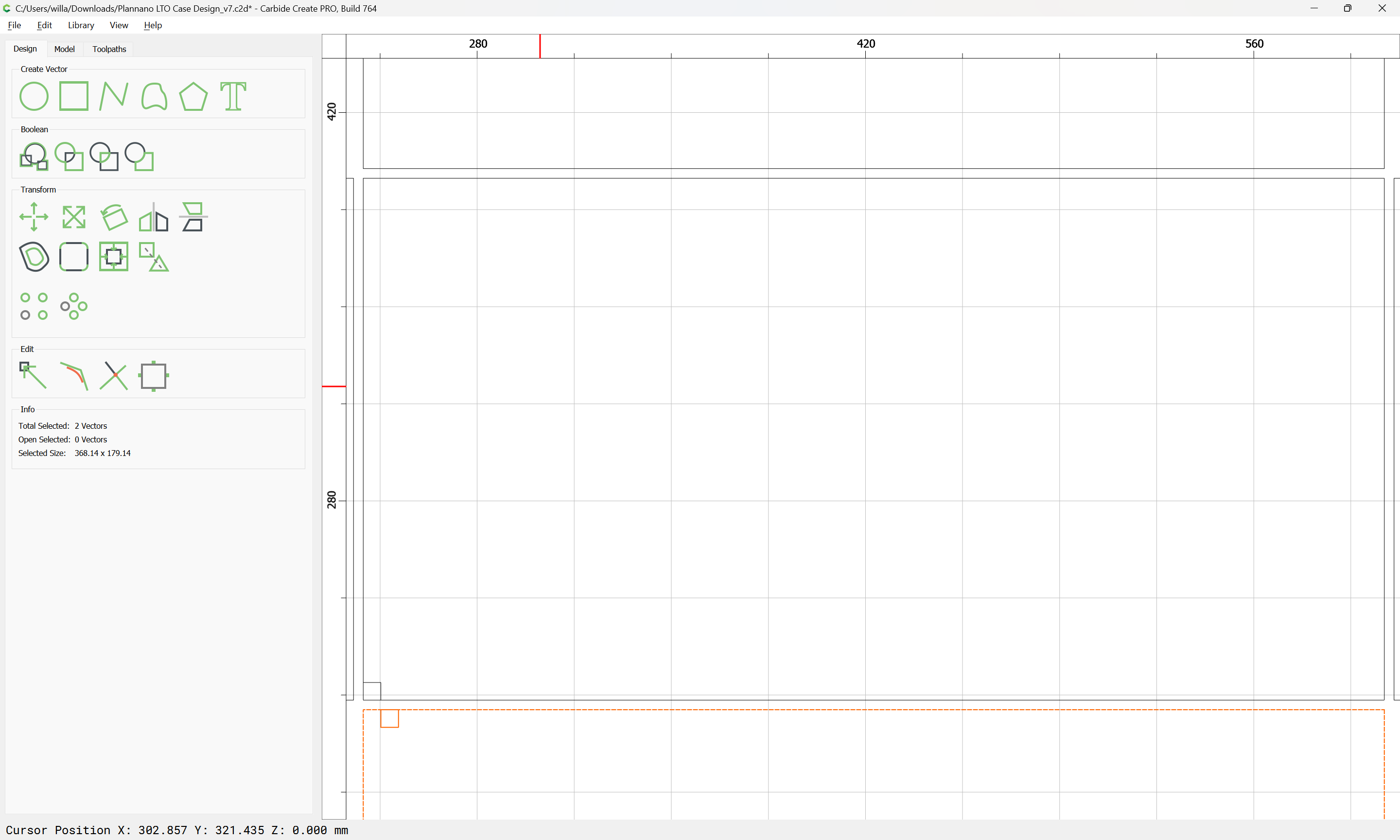
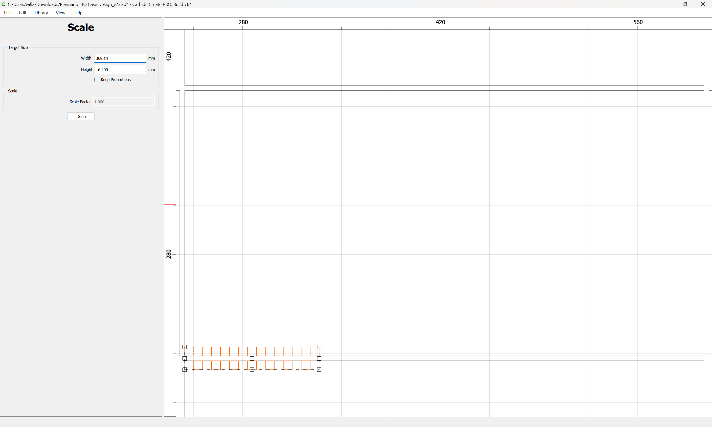
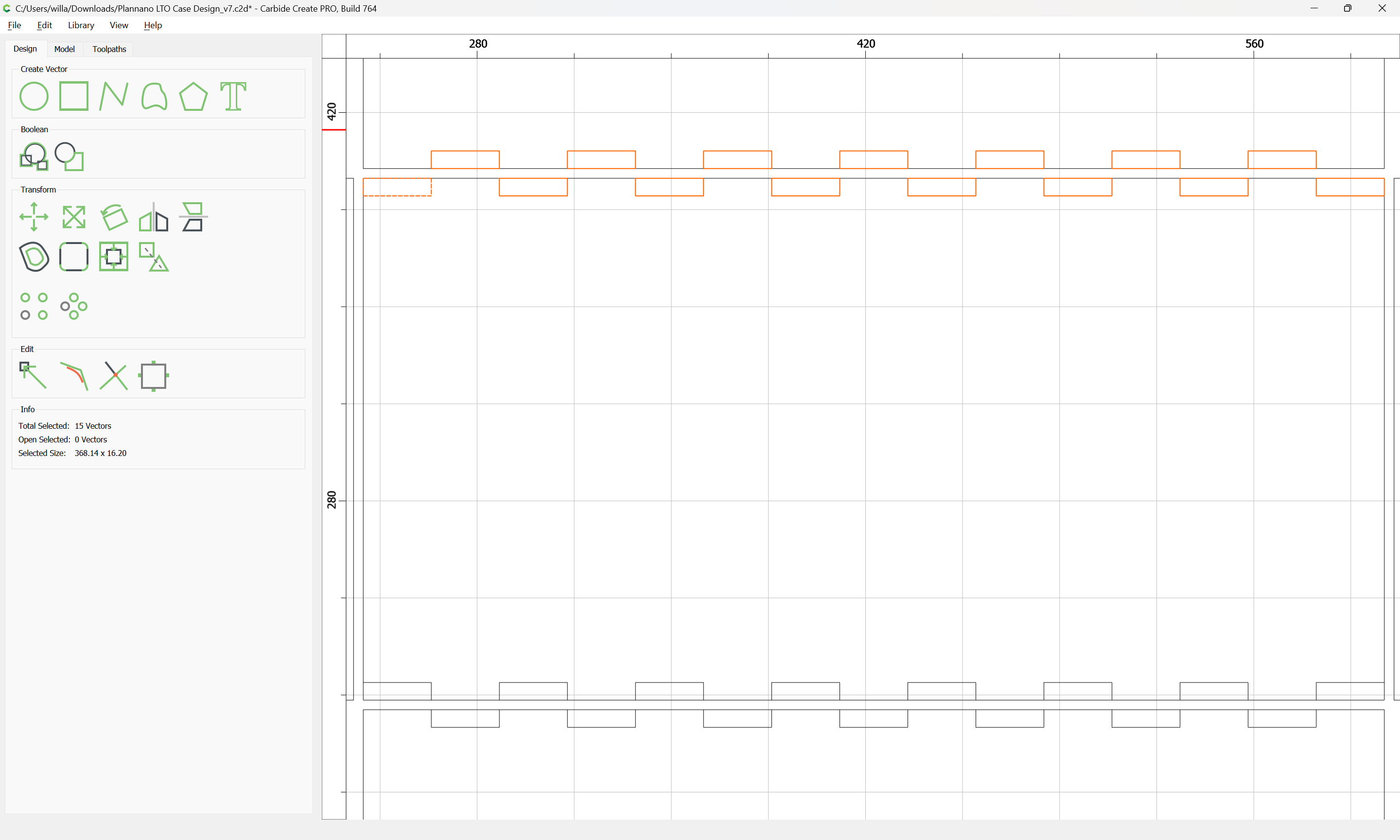
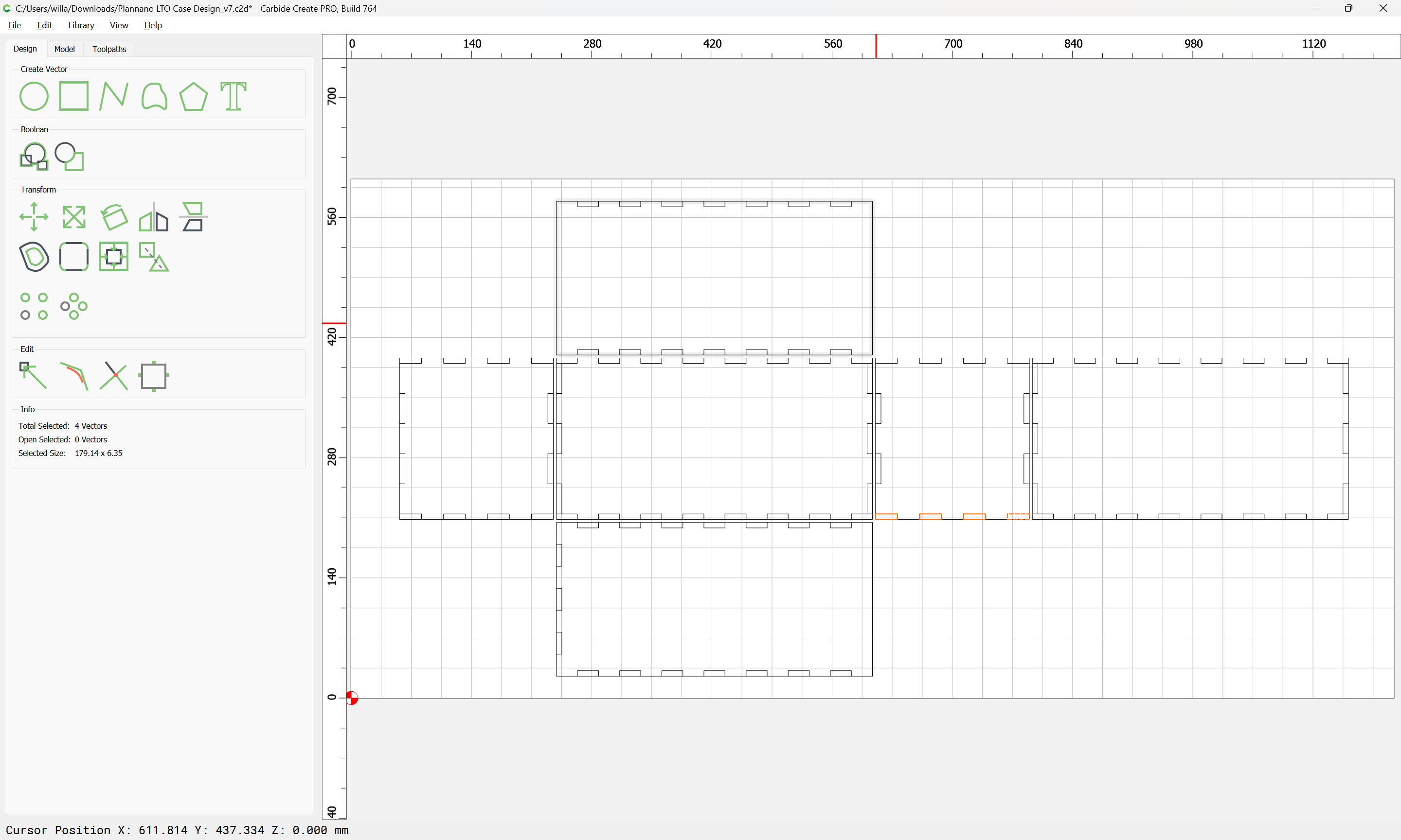
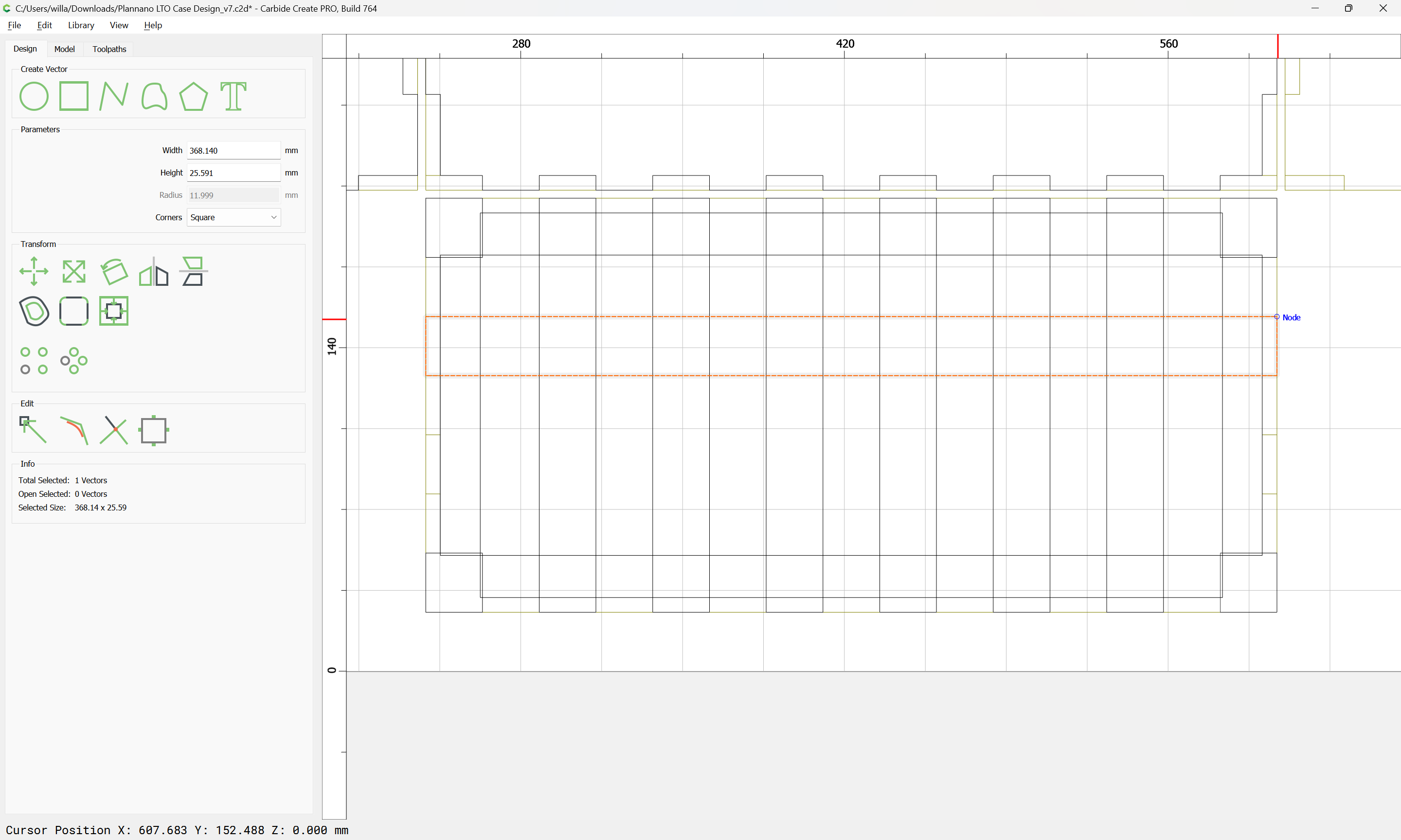
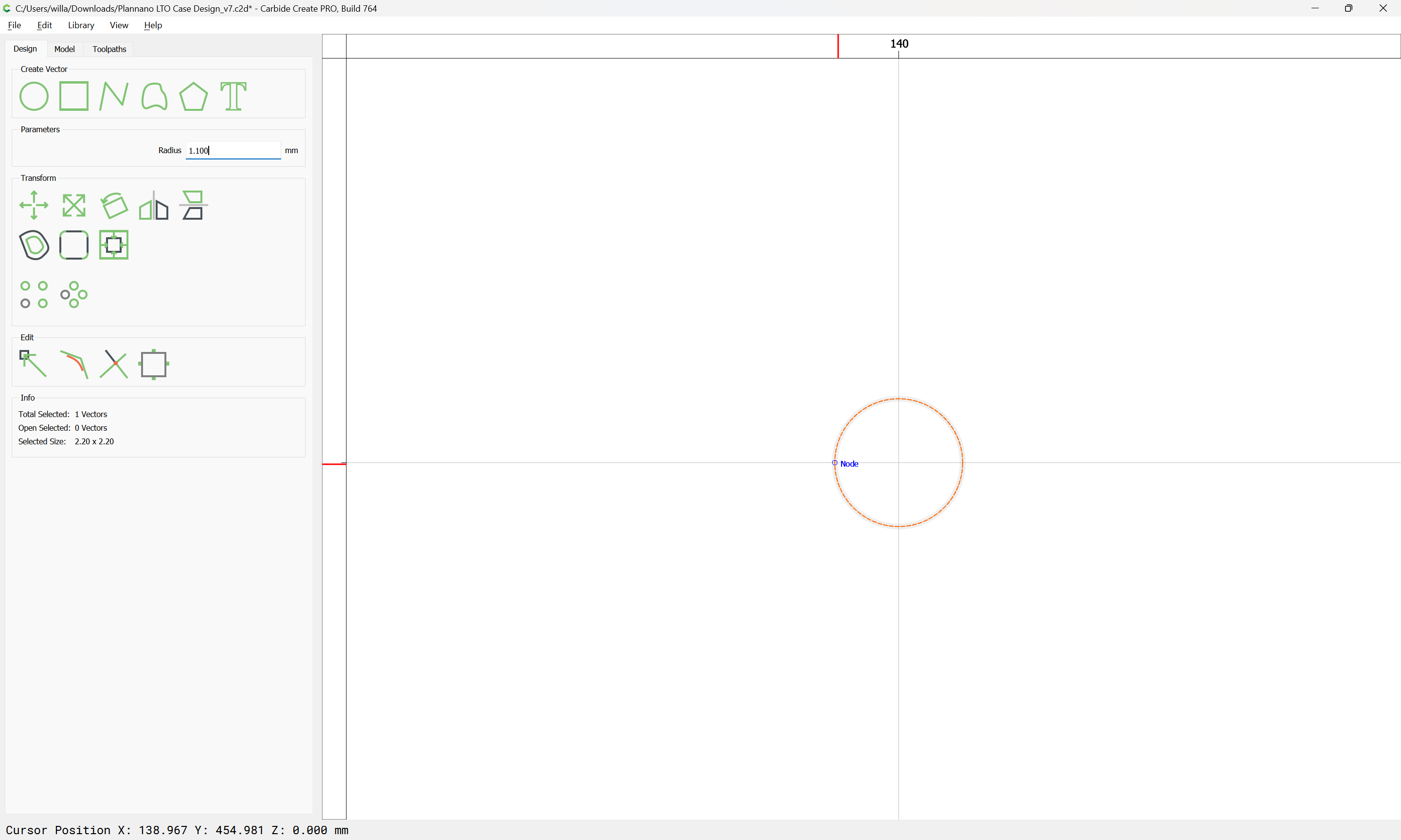
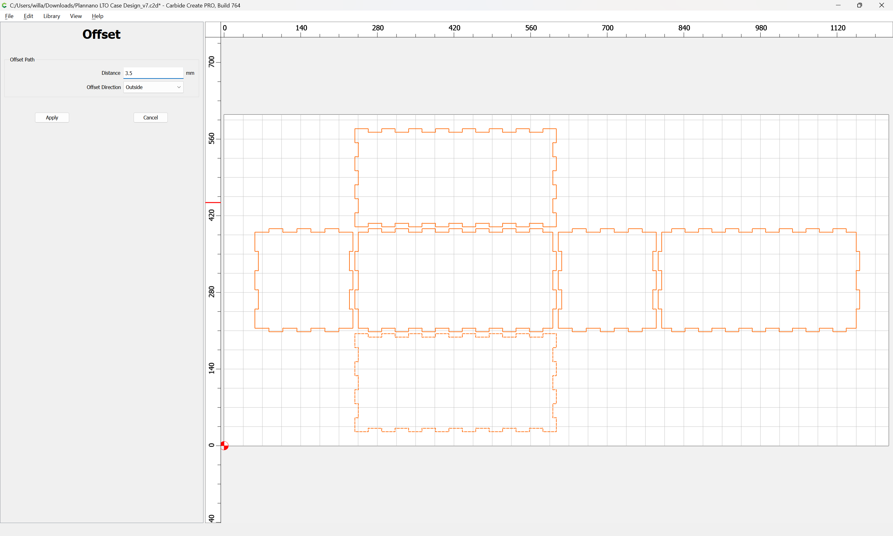
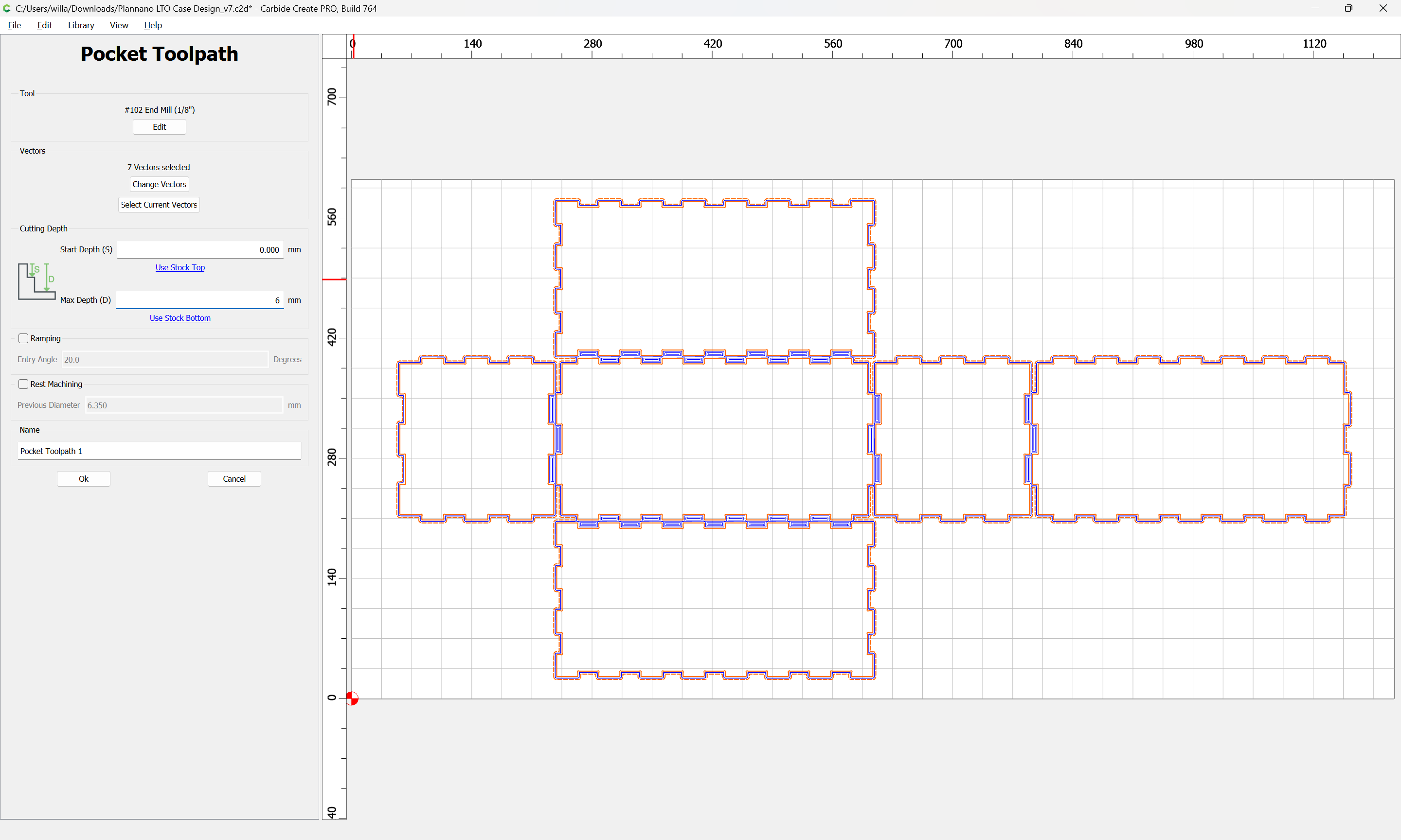
First consideration is the parts need to be separated enough to get an endmill in-between them (unless using a V endmill for the joinery — see below).
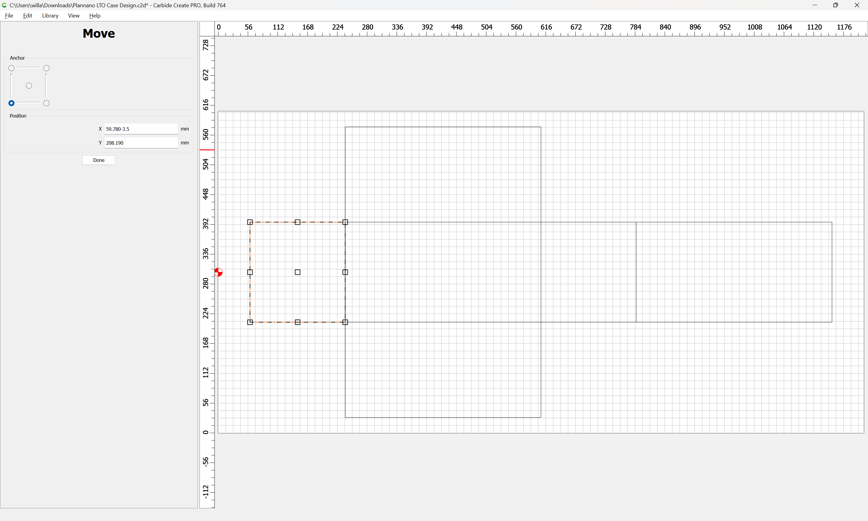
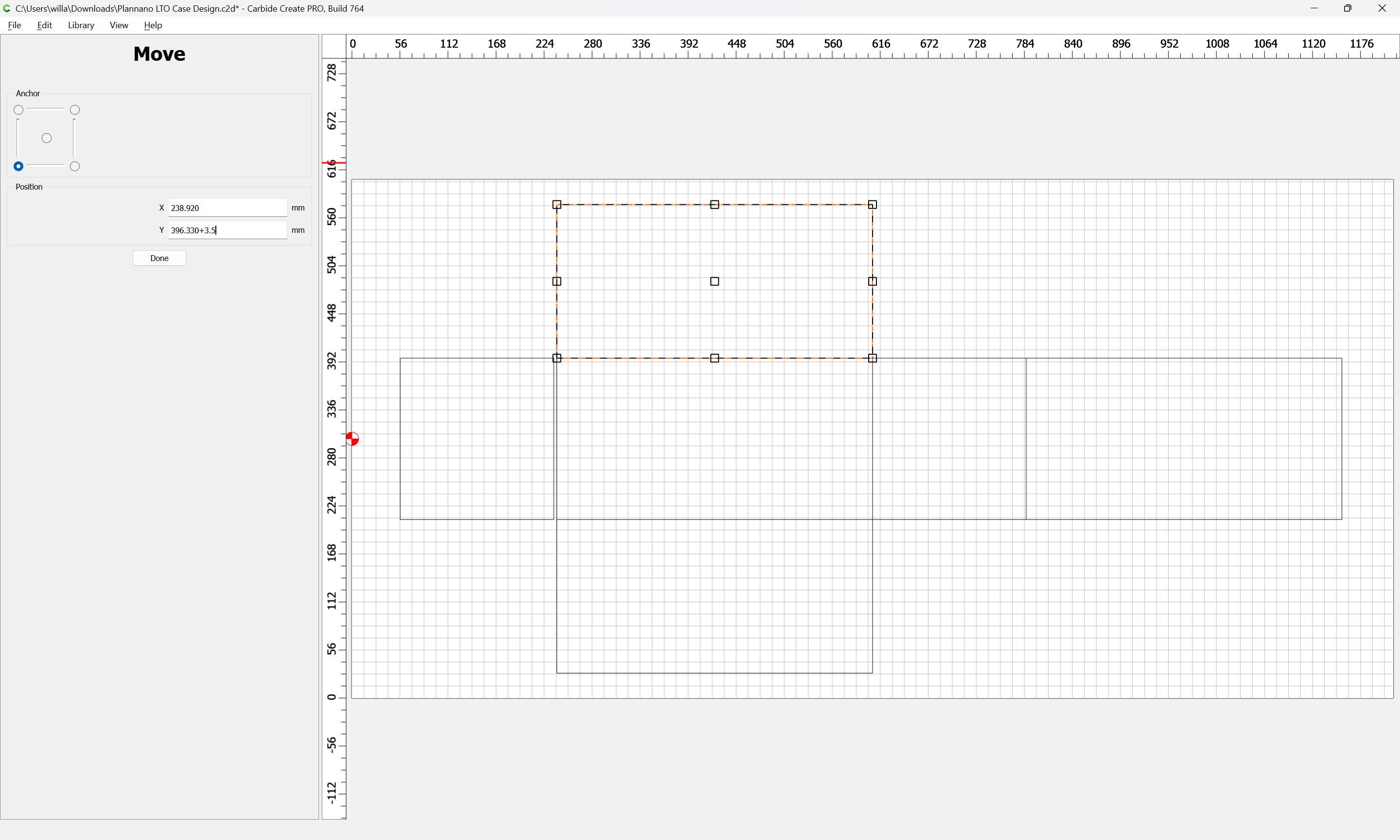
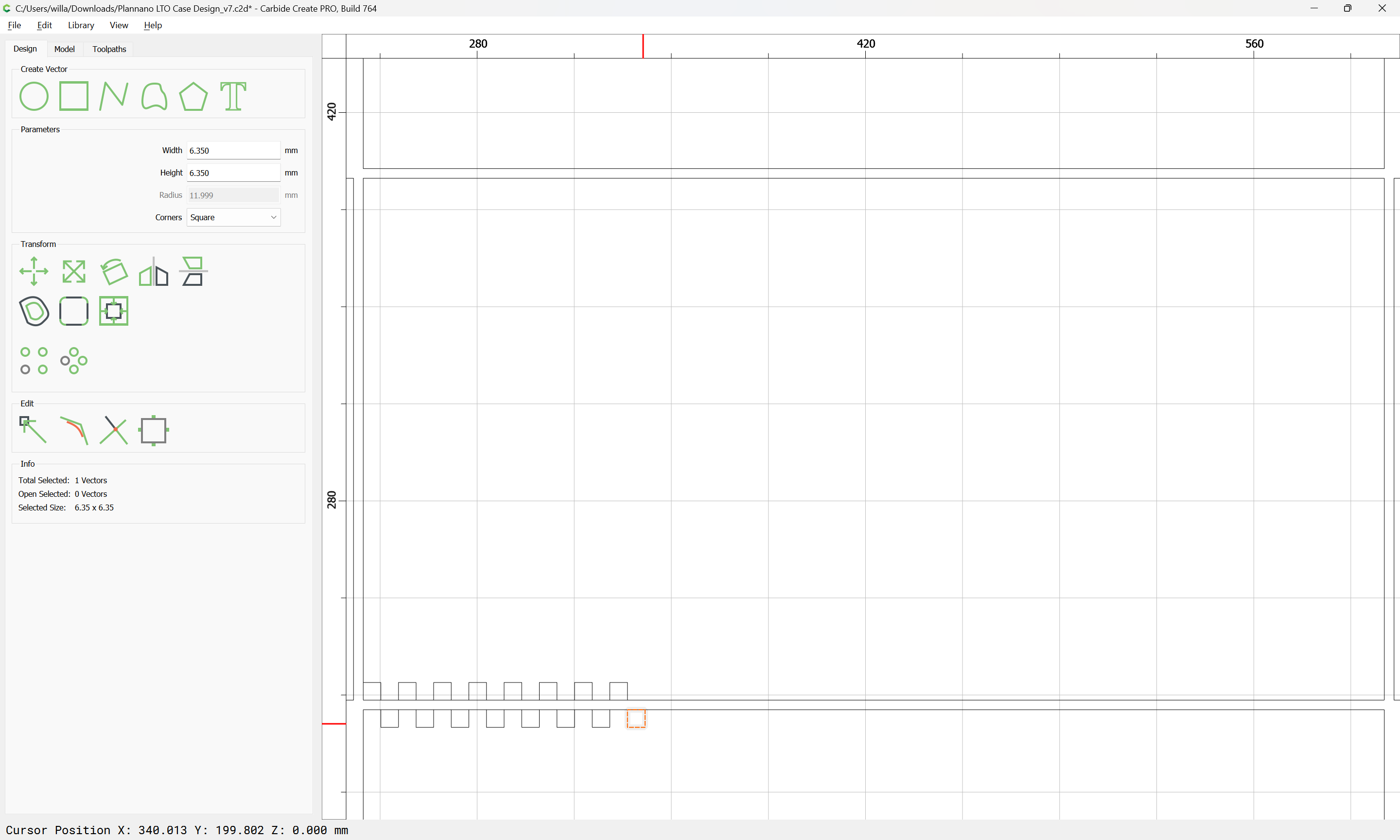
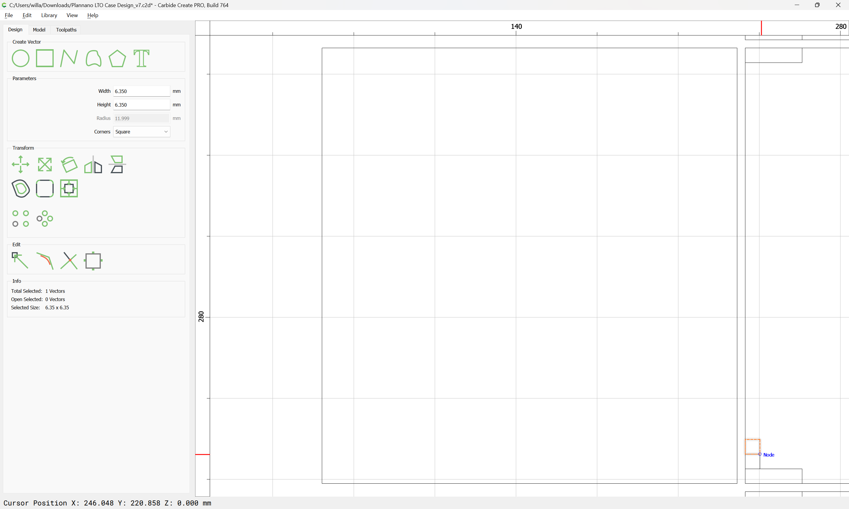
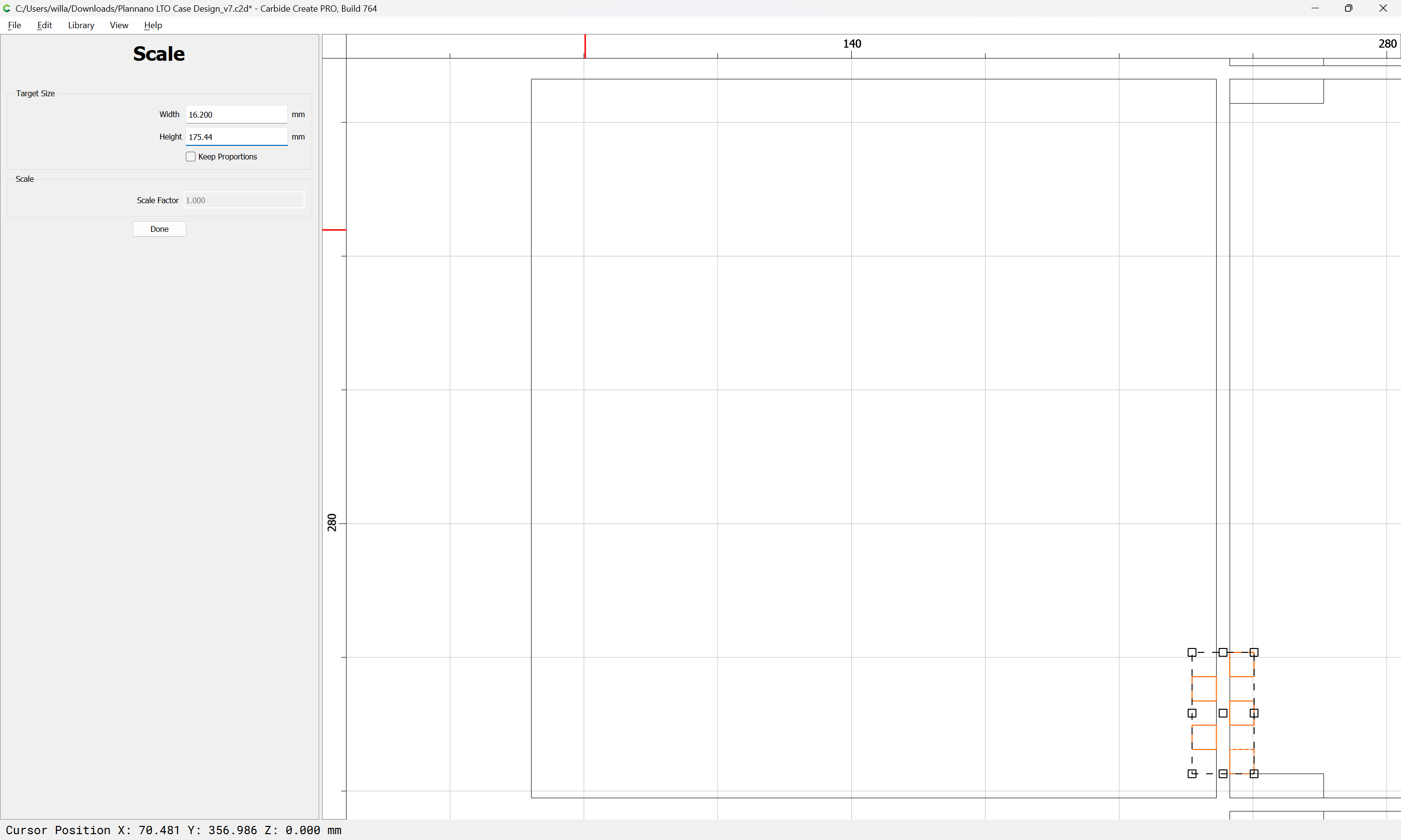
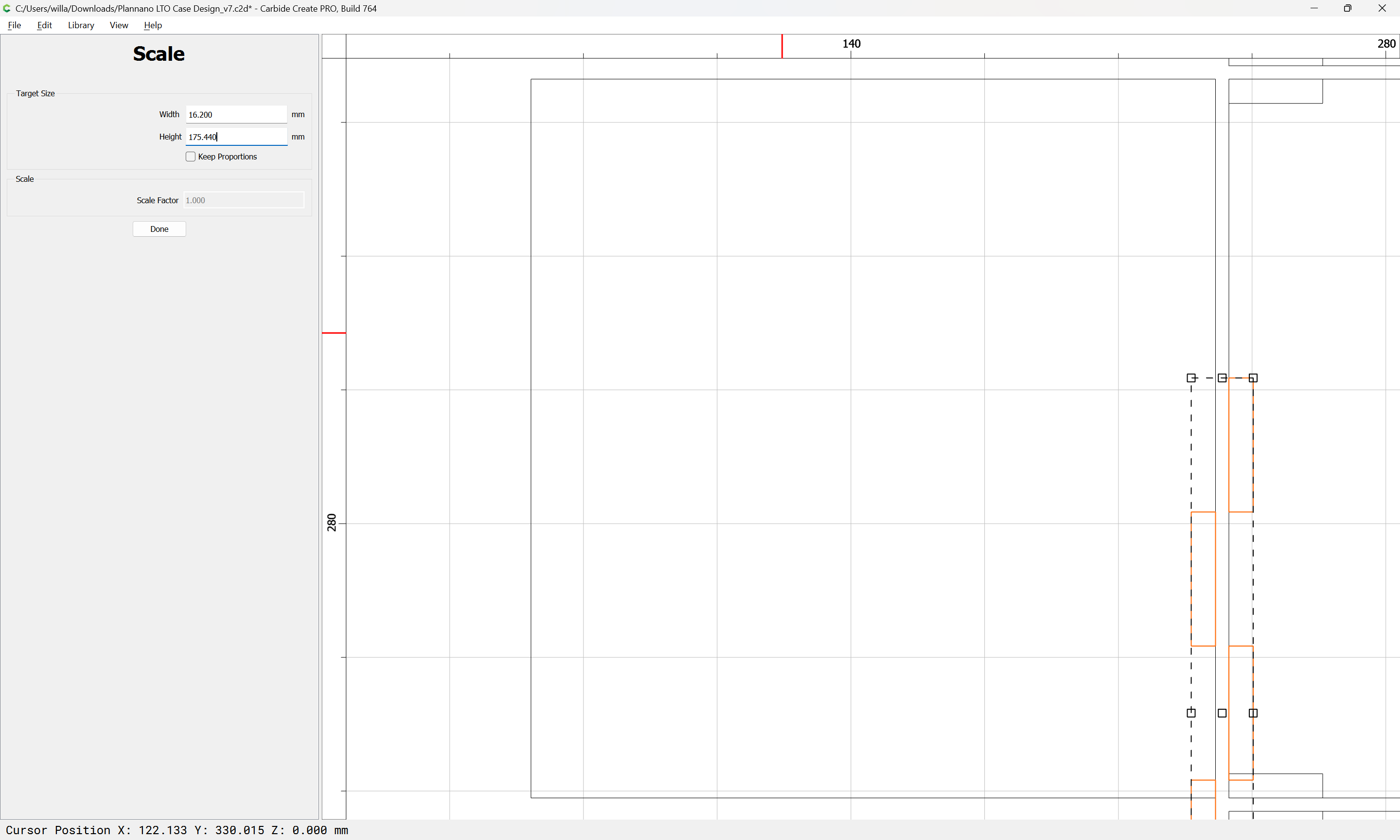
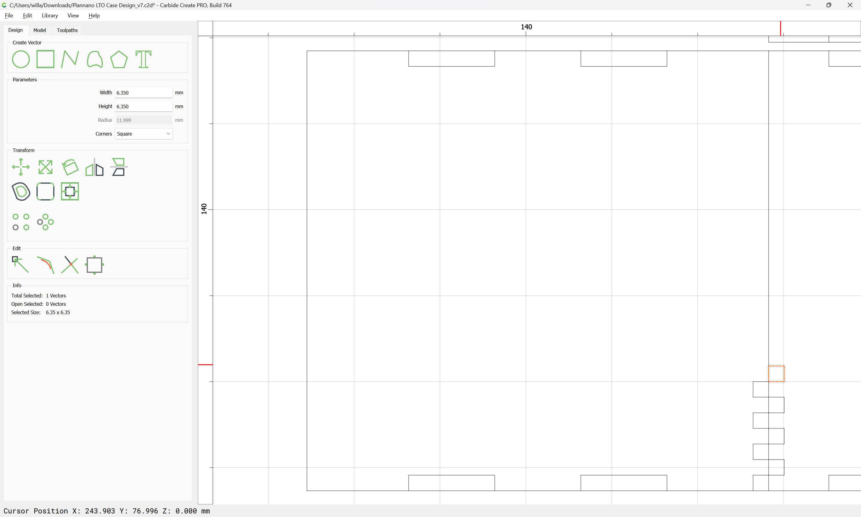
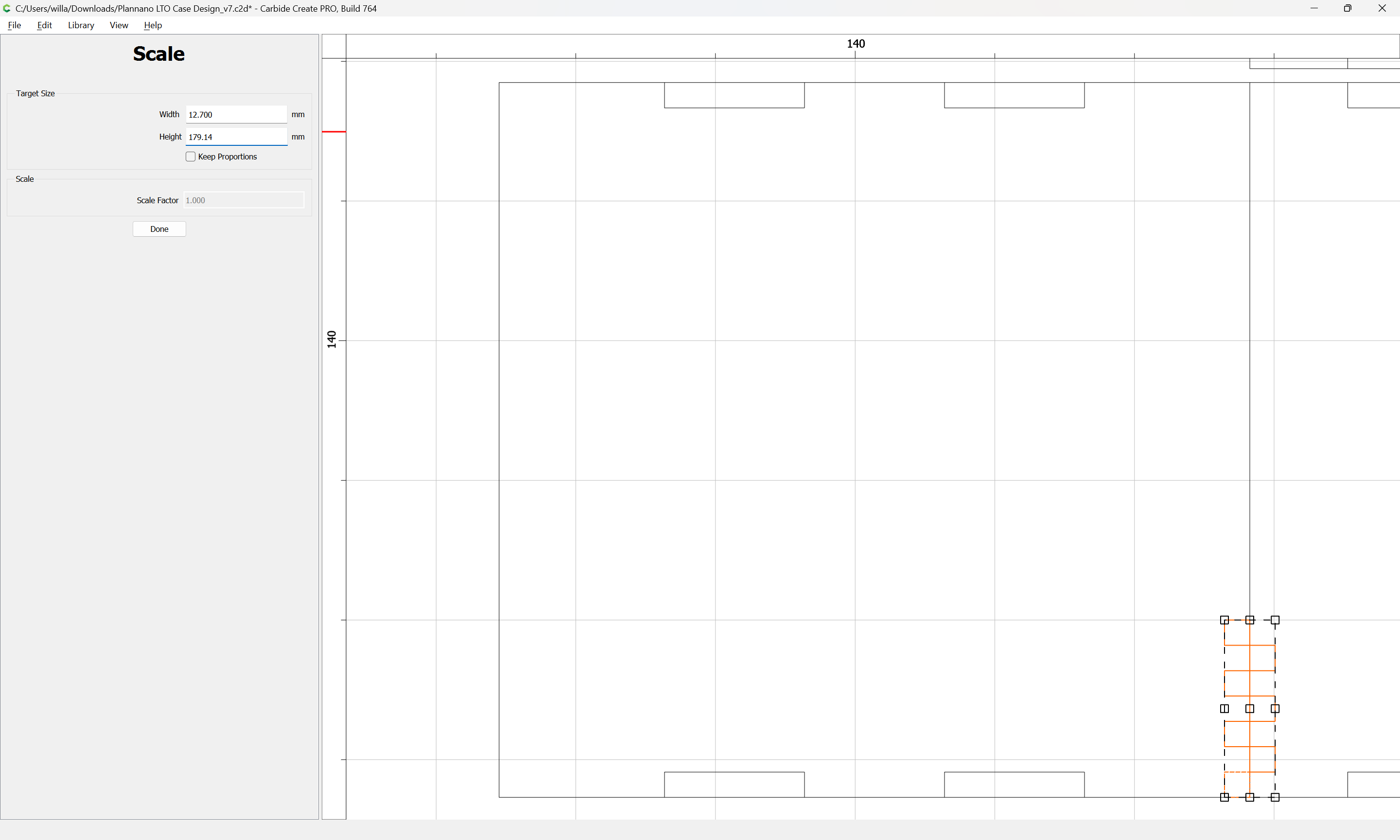
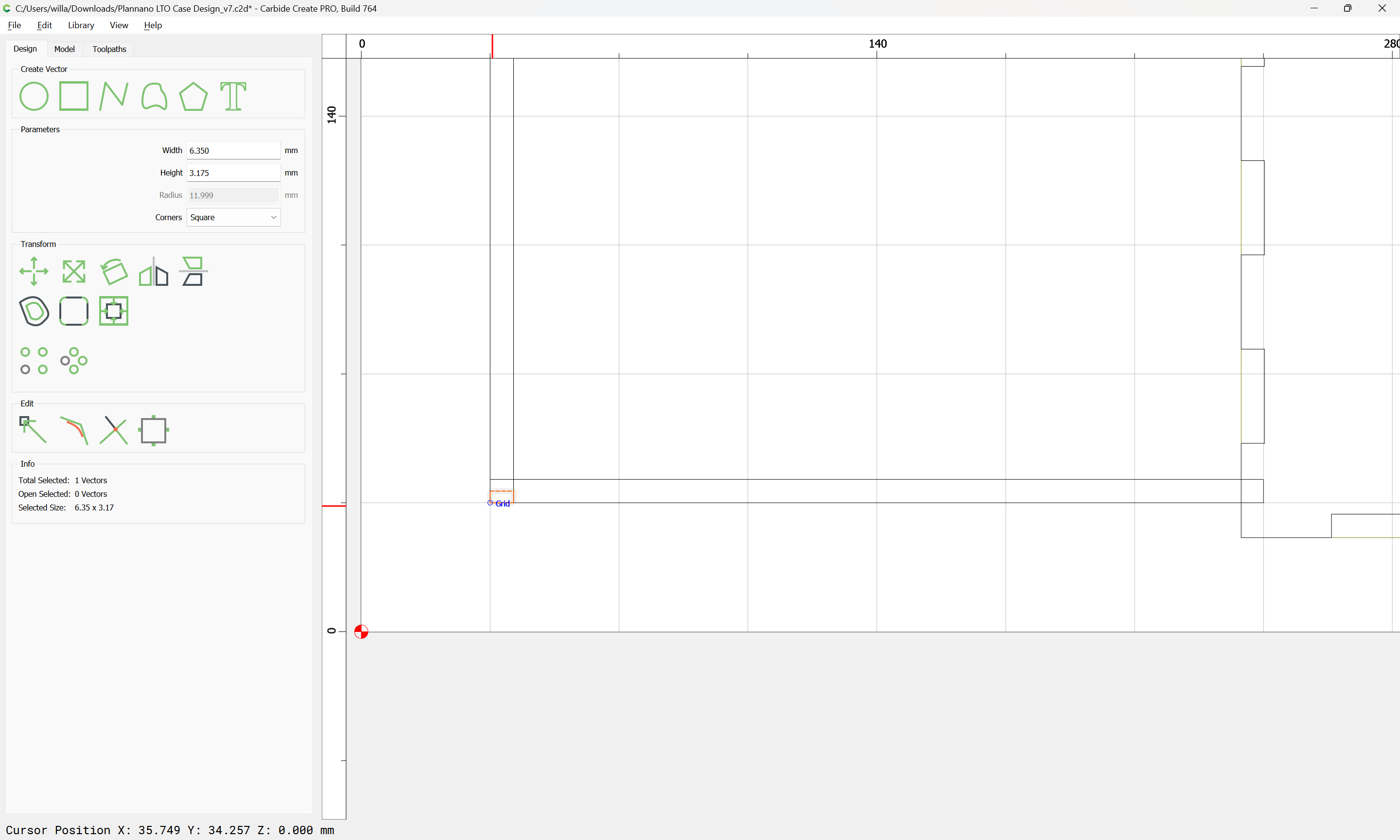
Since the stock thickness is only 0.25 inches (6.35mm) we have a bit of flexibility here — a #102 should be a workable size, so we will put 3.5mm in-between each part (that being a rounding up of the 3.175mm diameter plus 10%):
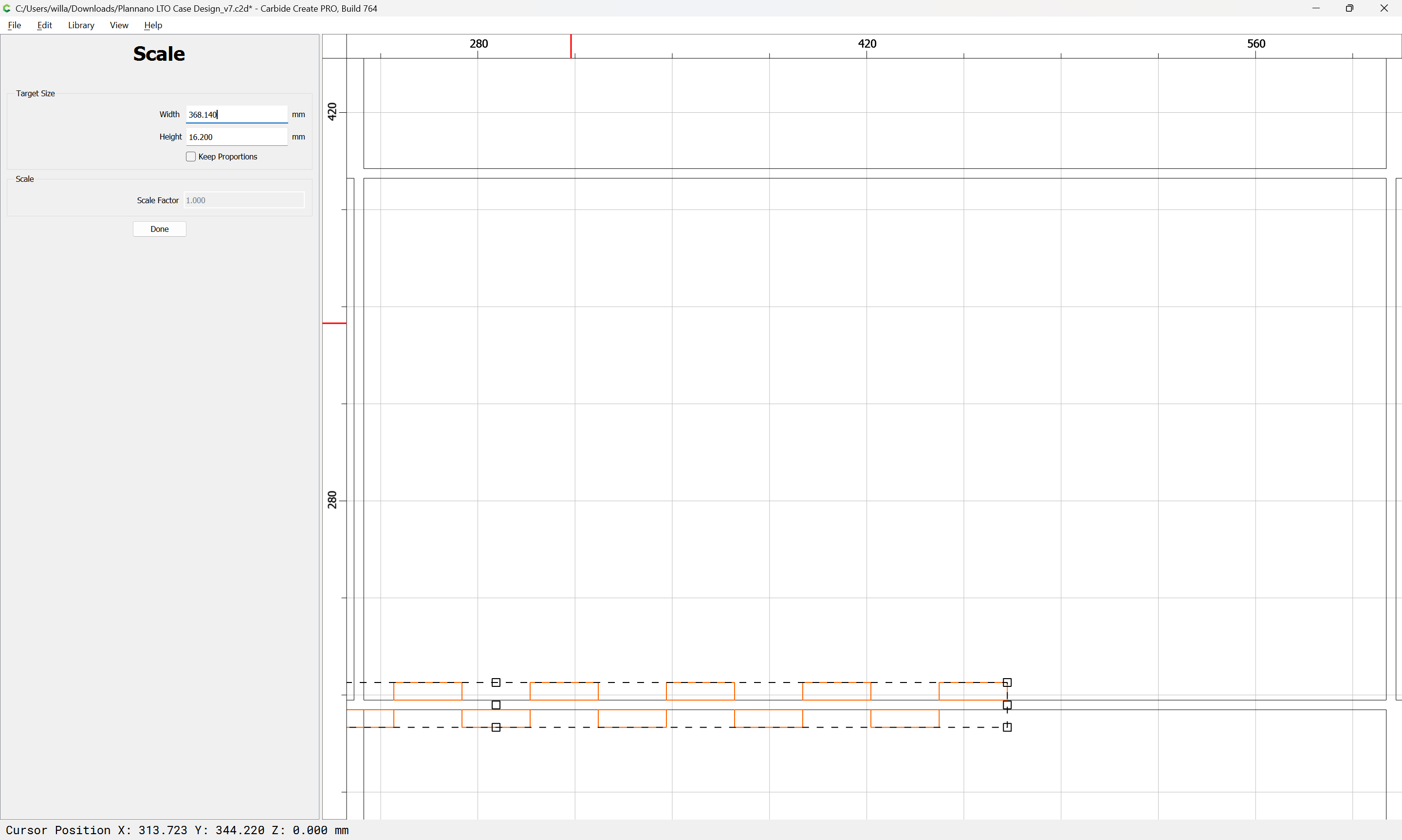
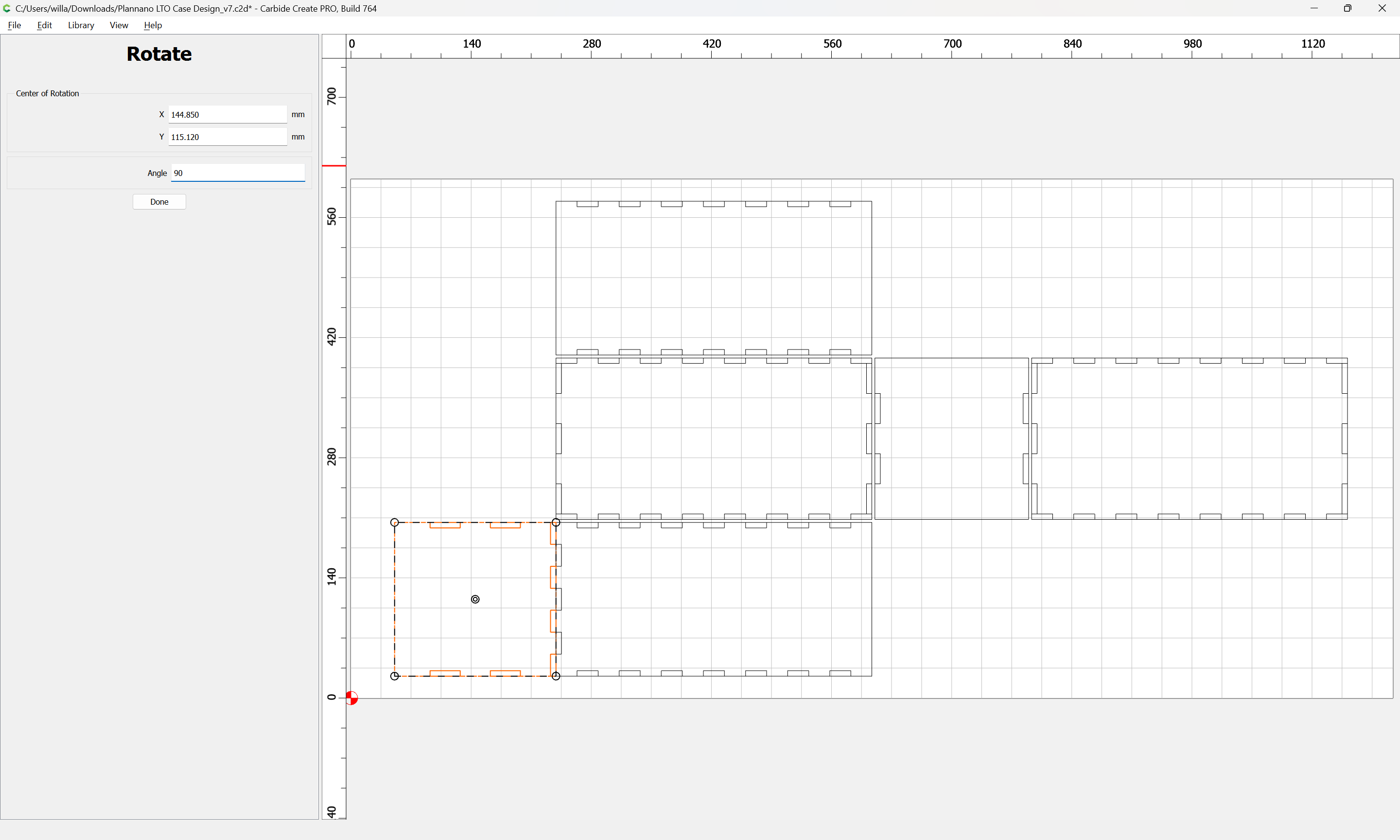
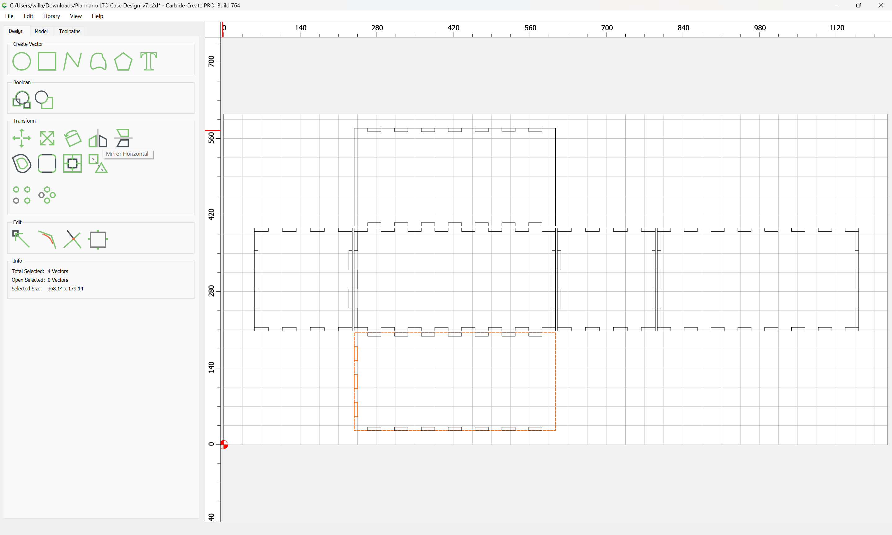
(the clever way to do this would be to set the grid size to match the dimension which we wish to move, or 10 times that amound and use the arrow nudges to shift things, holding down shift to move 1/10th the grid distance)
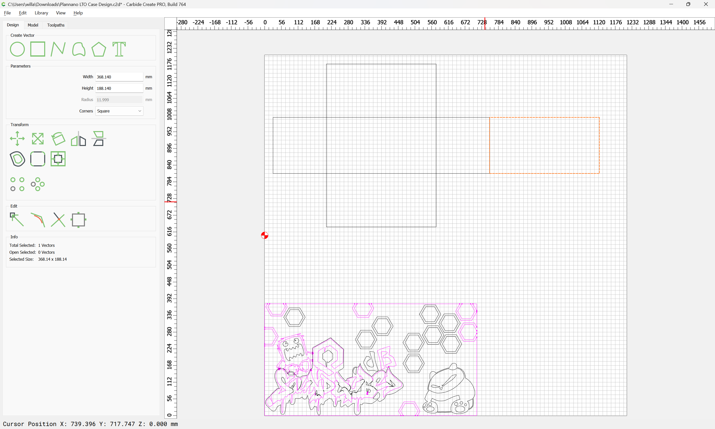
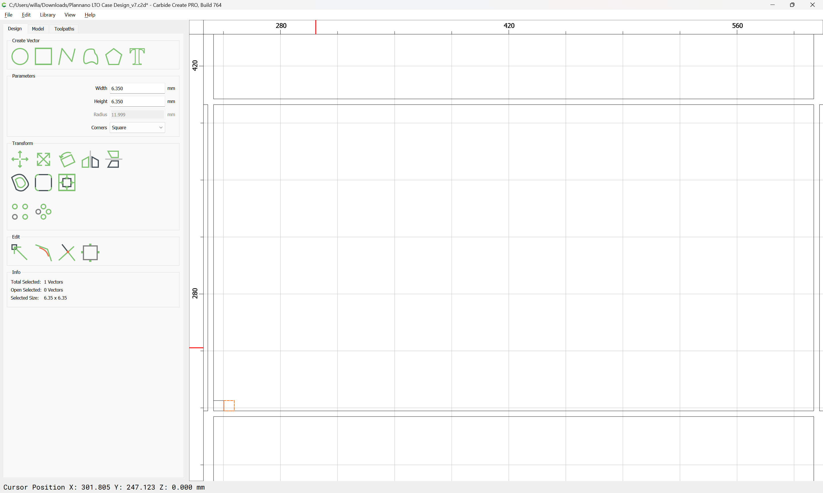
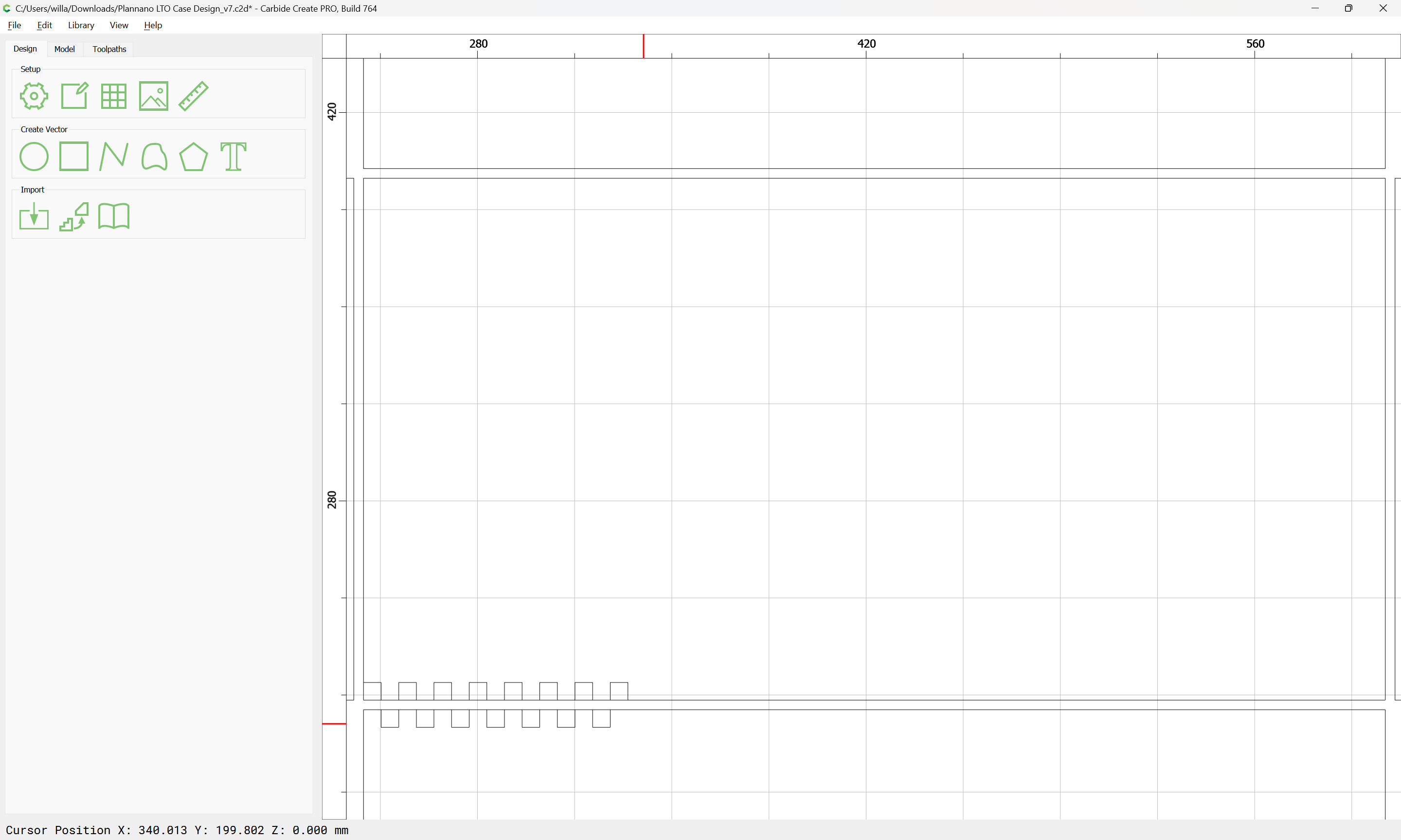
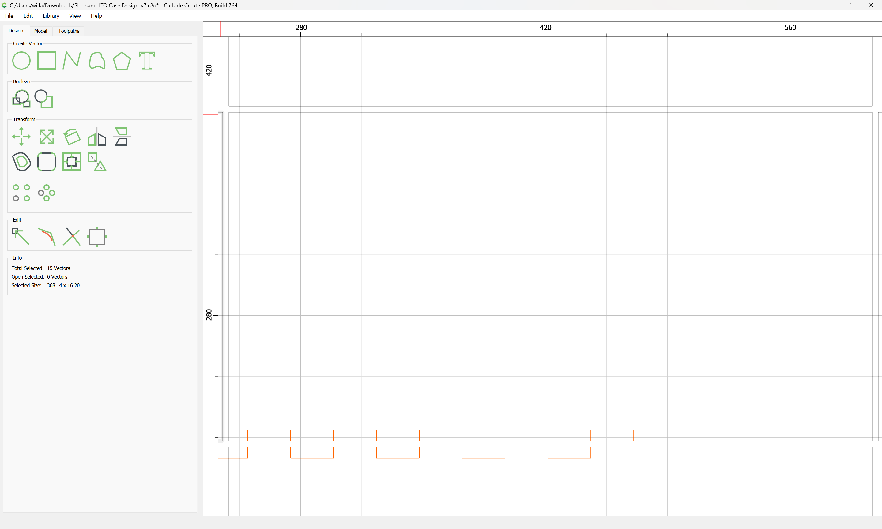
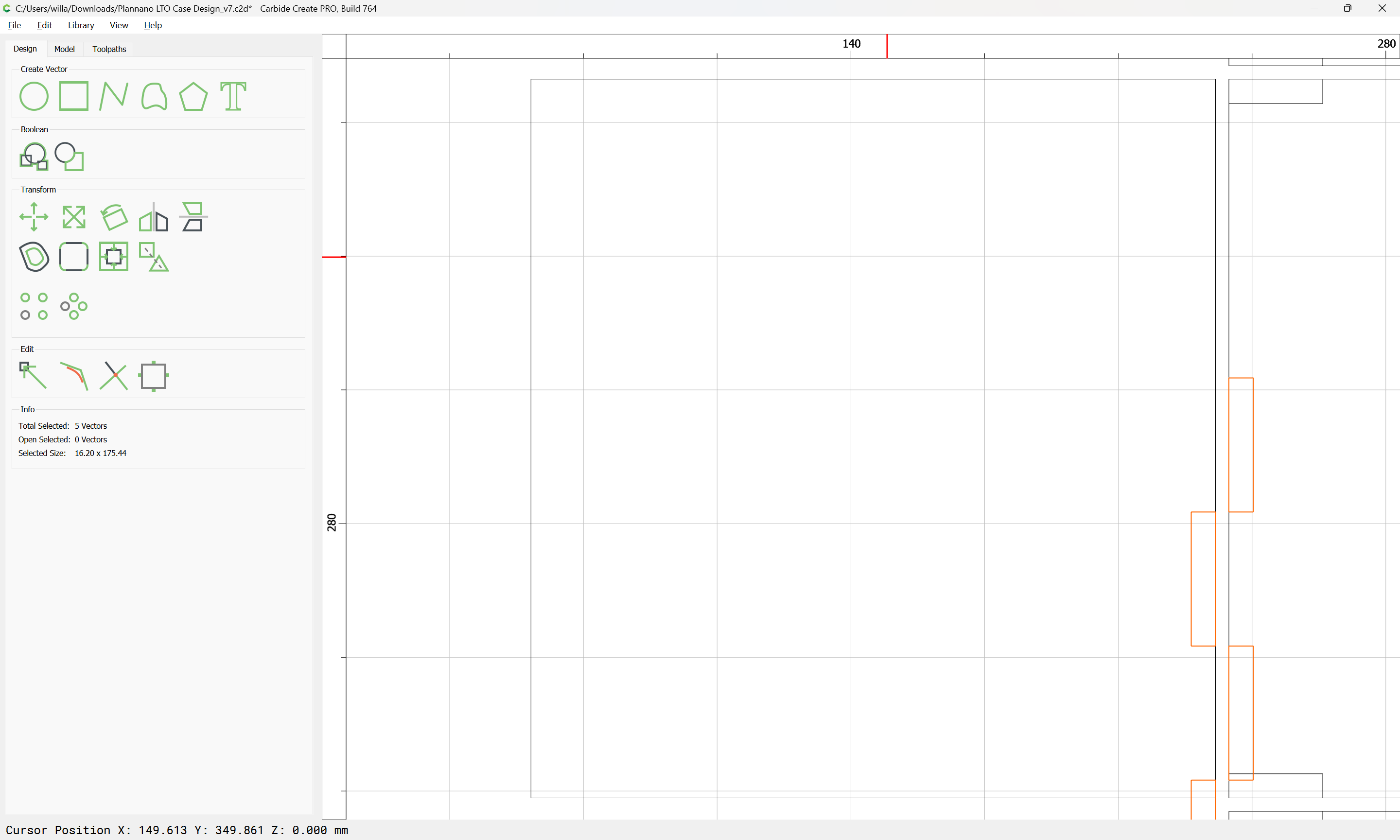
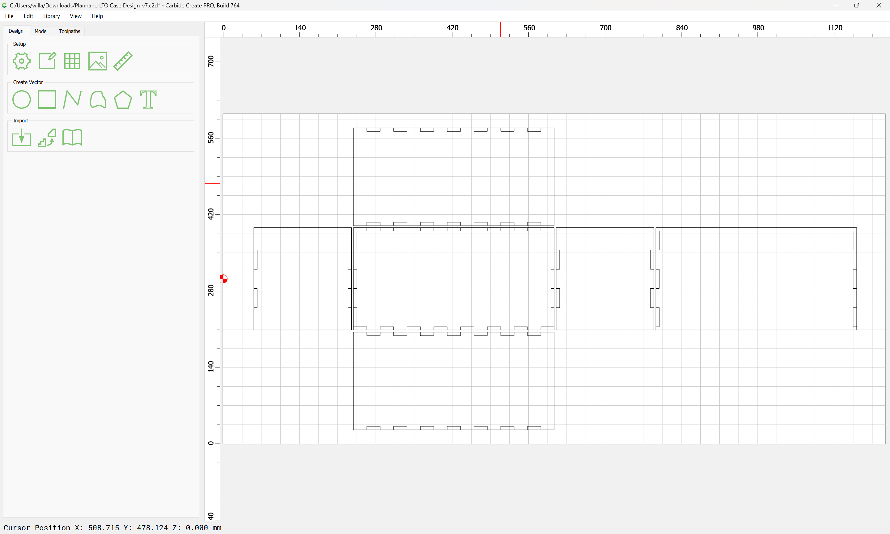
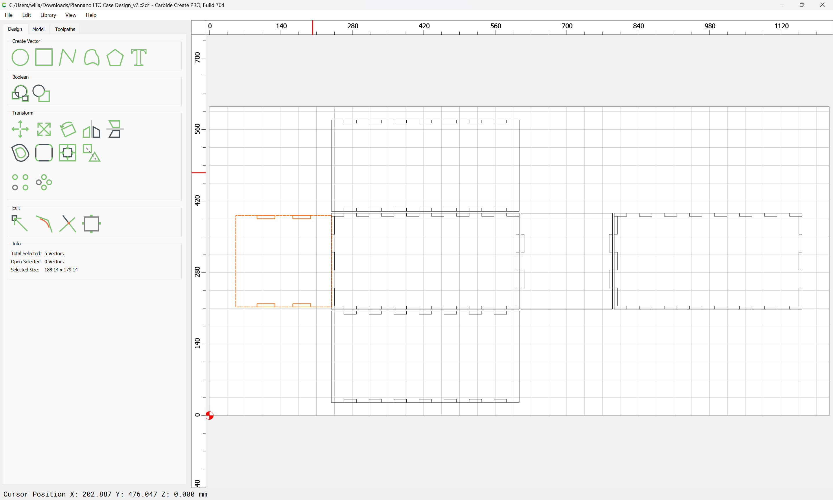
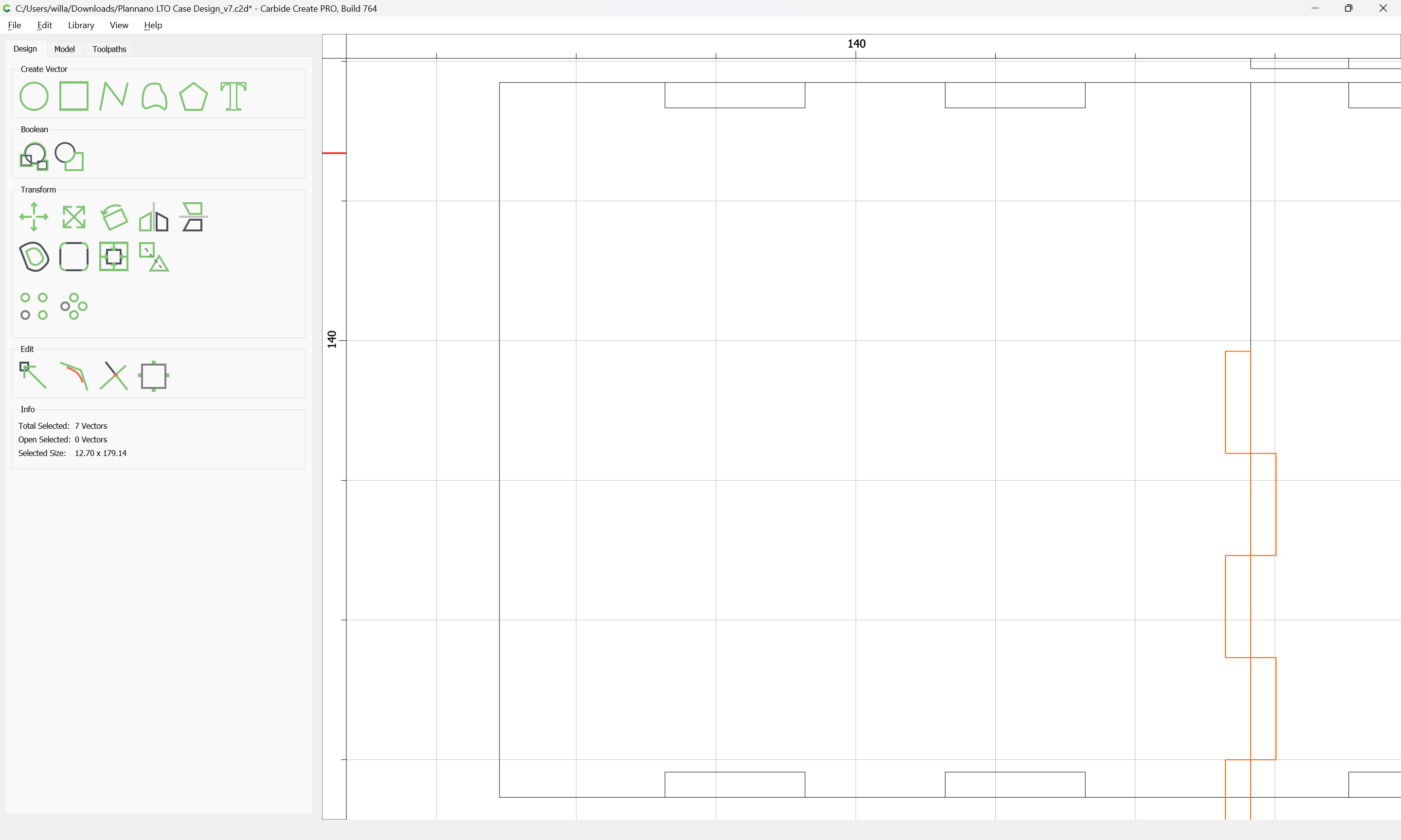
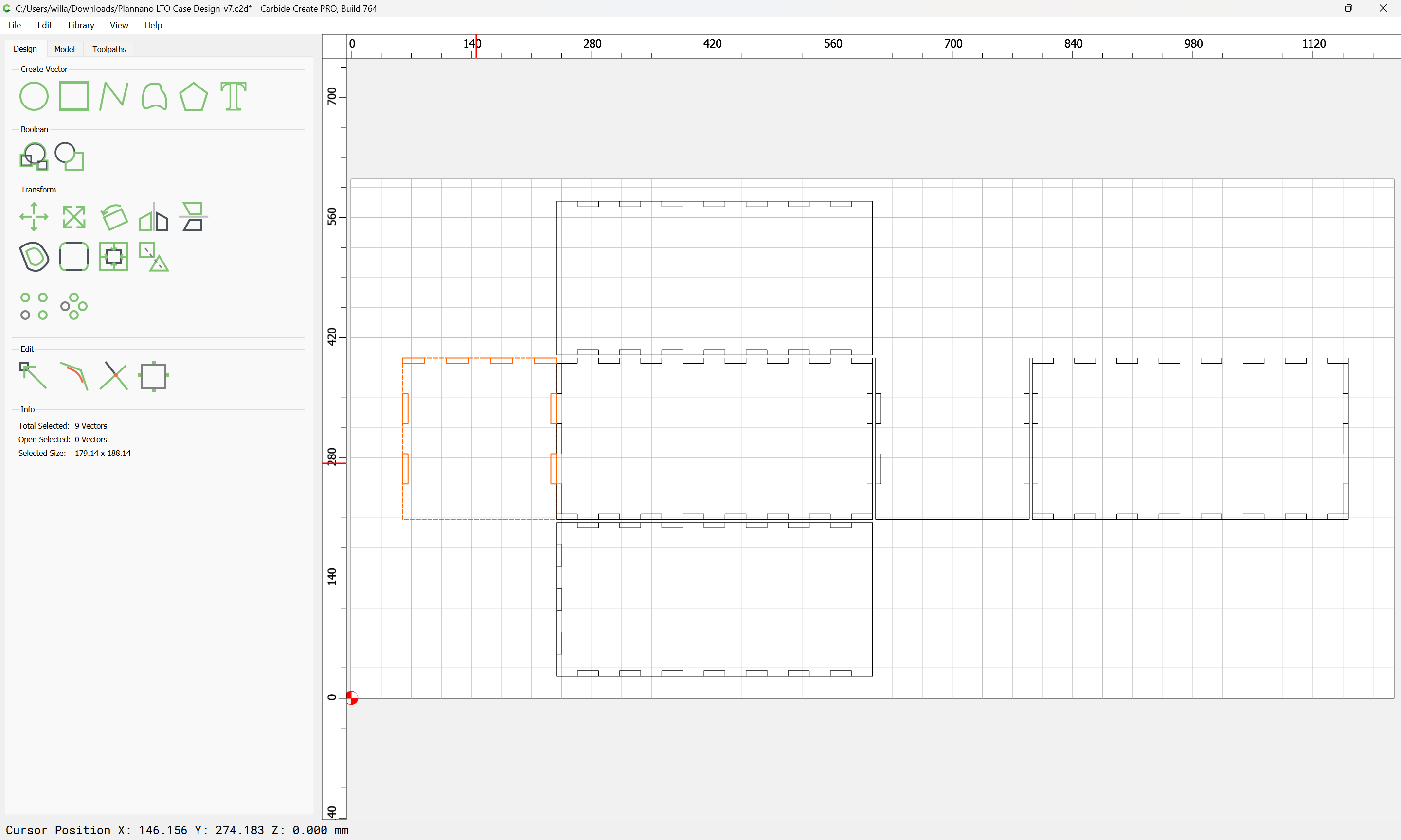
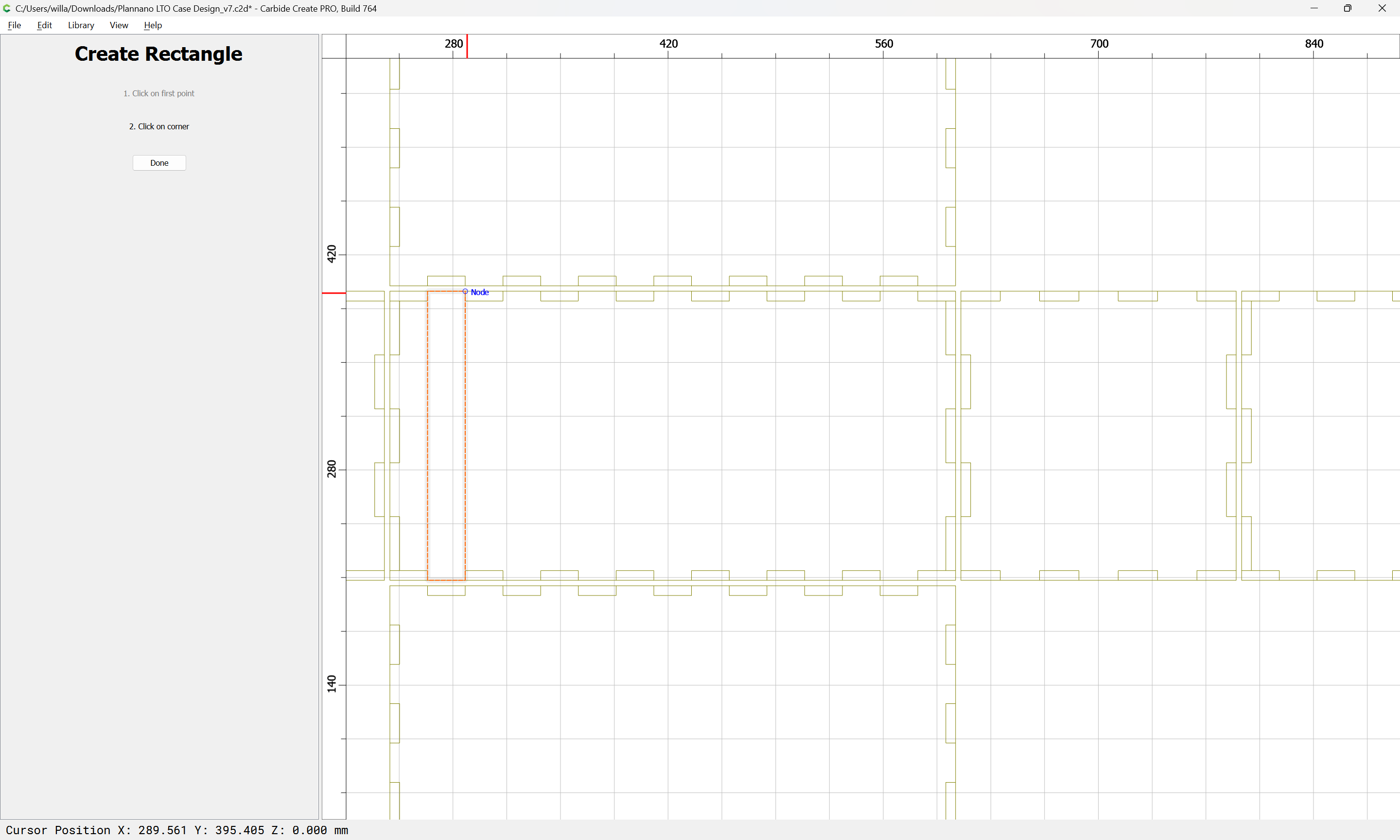
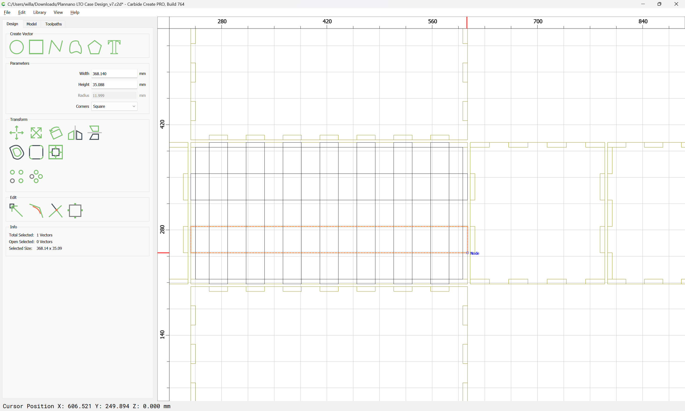
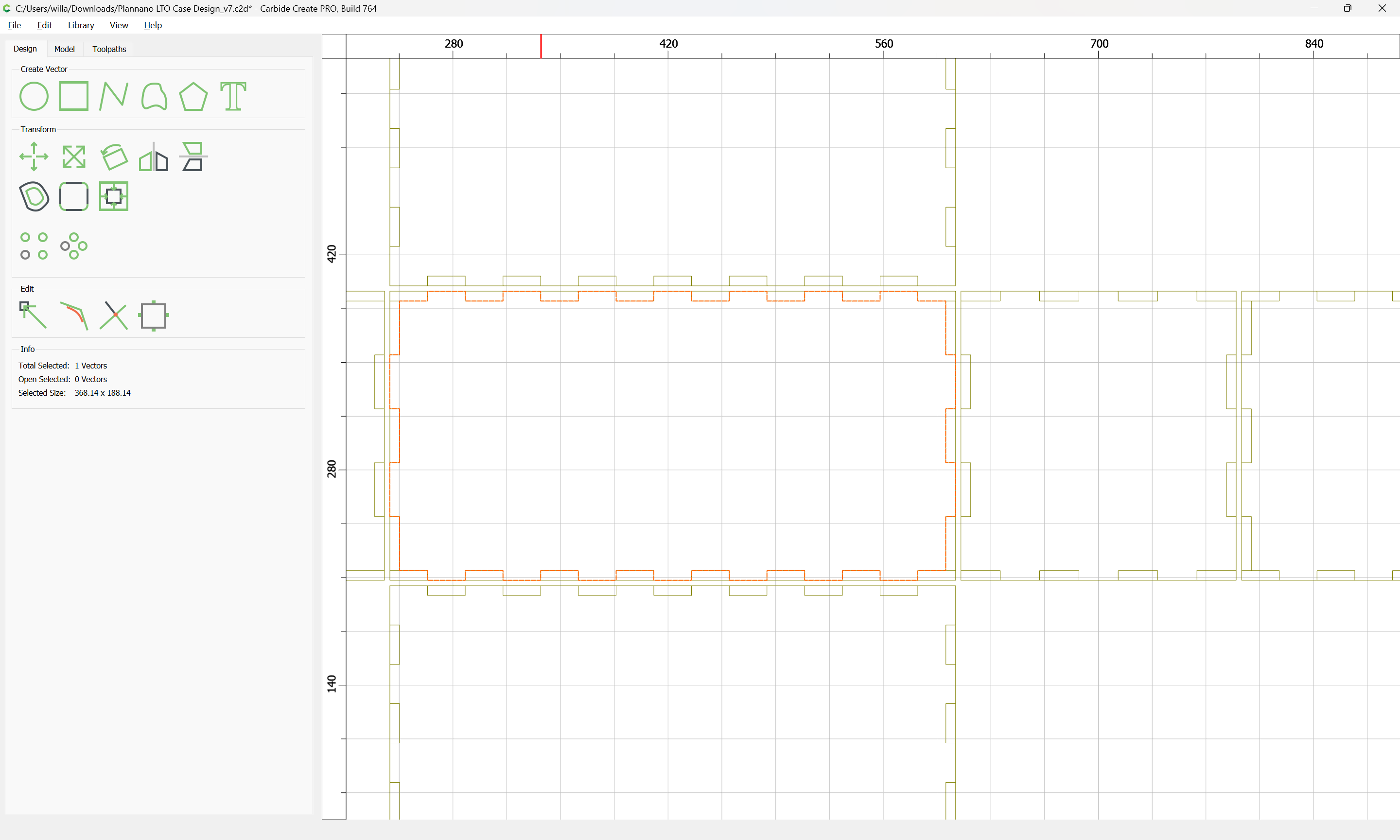
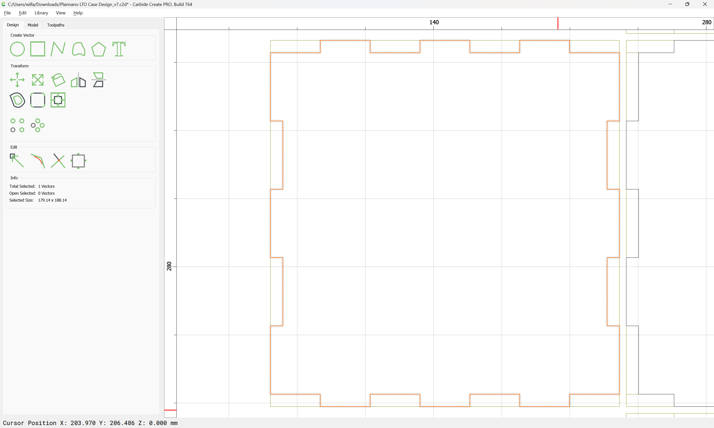
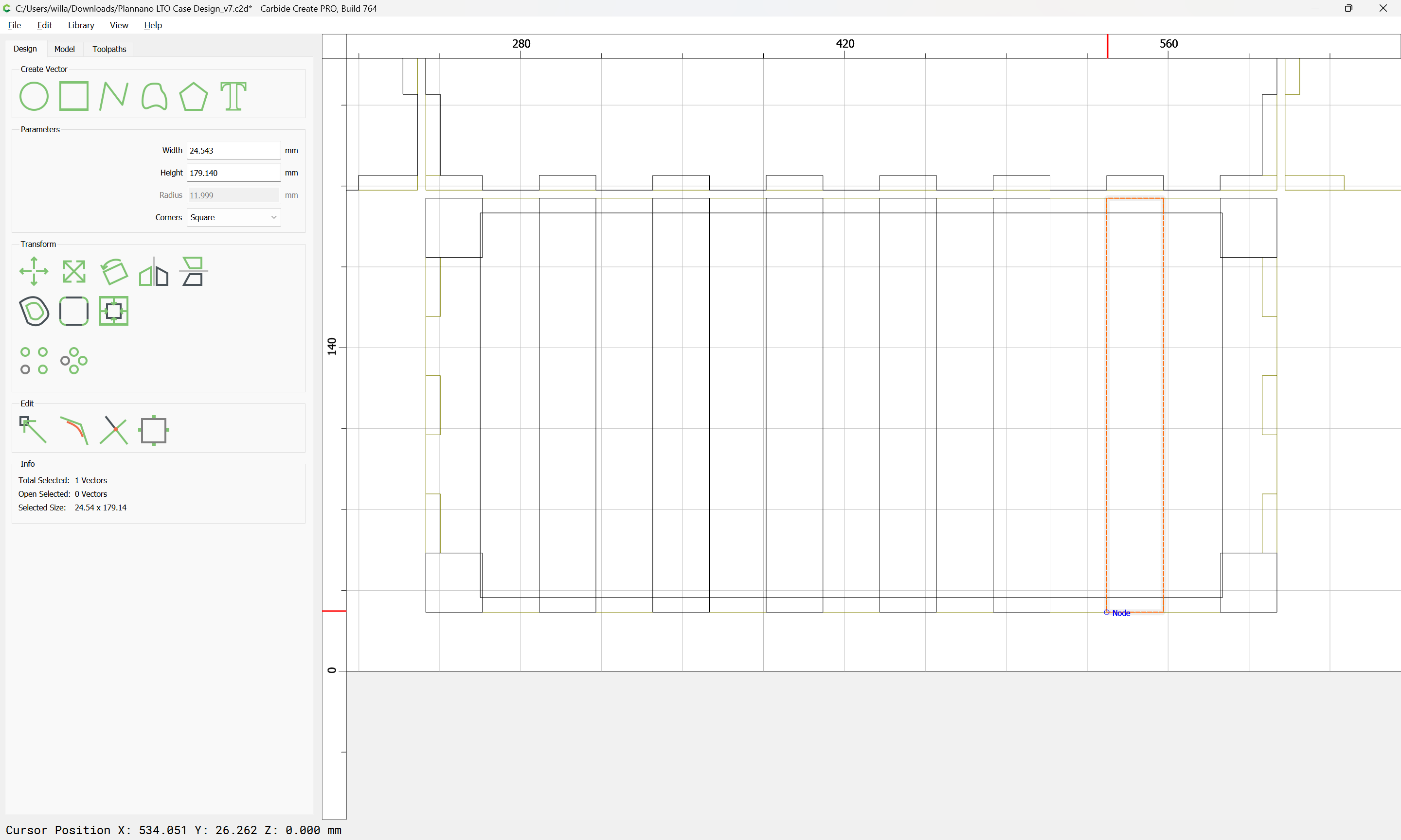
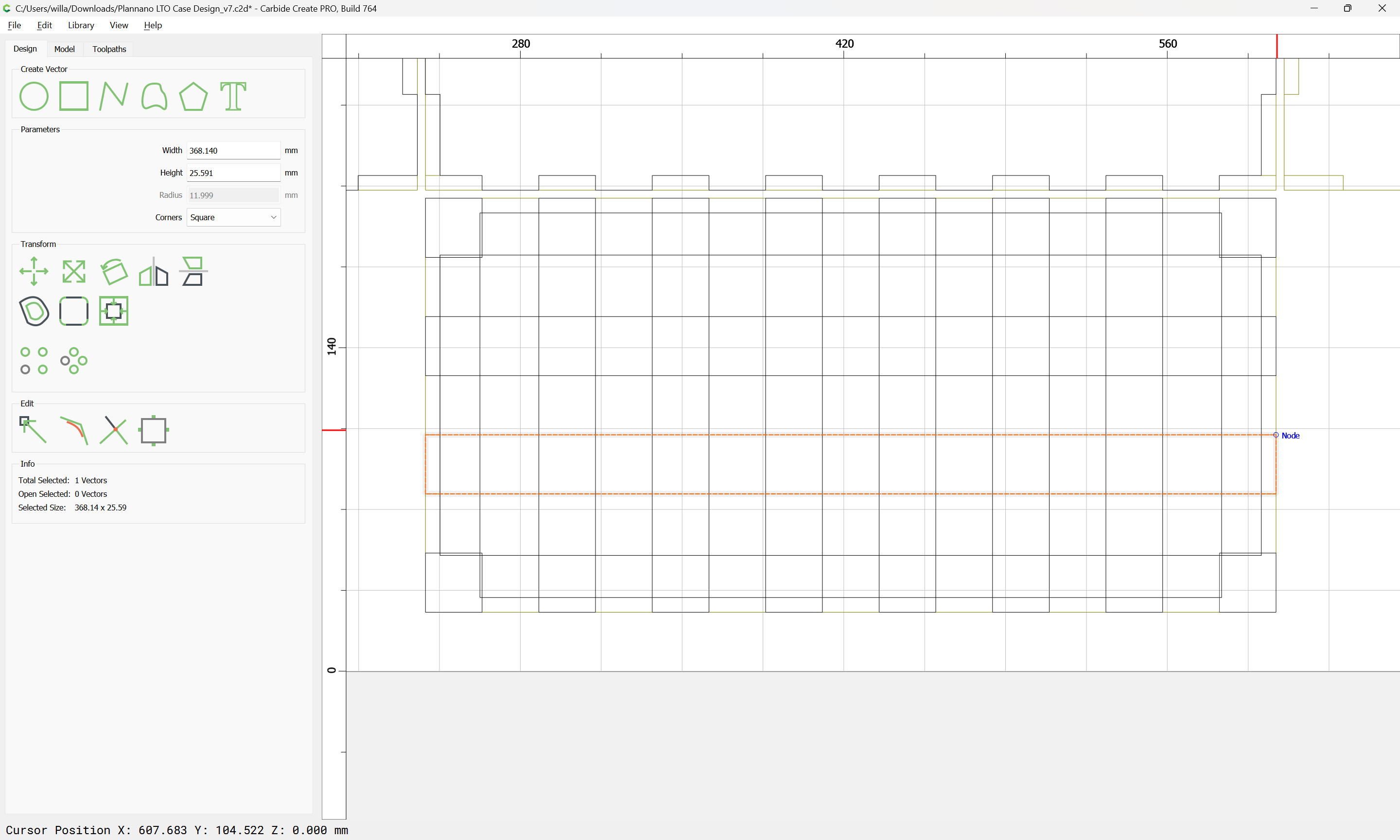
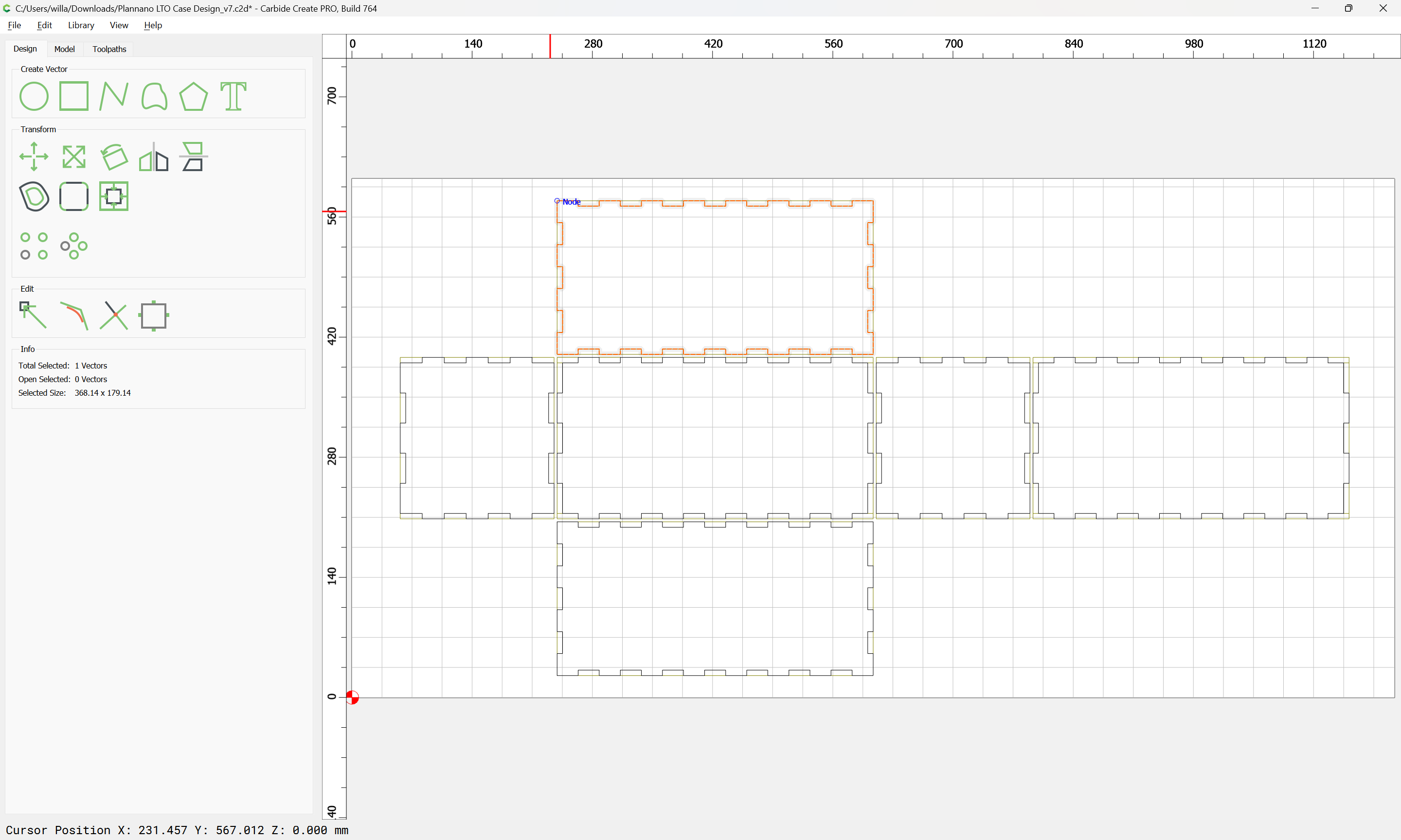
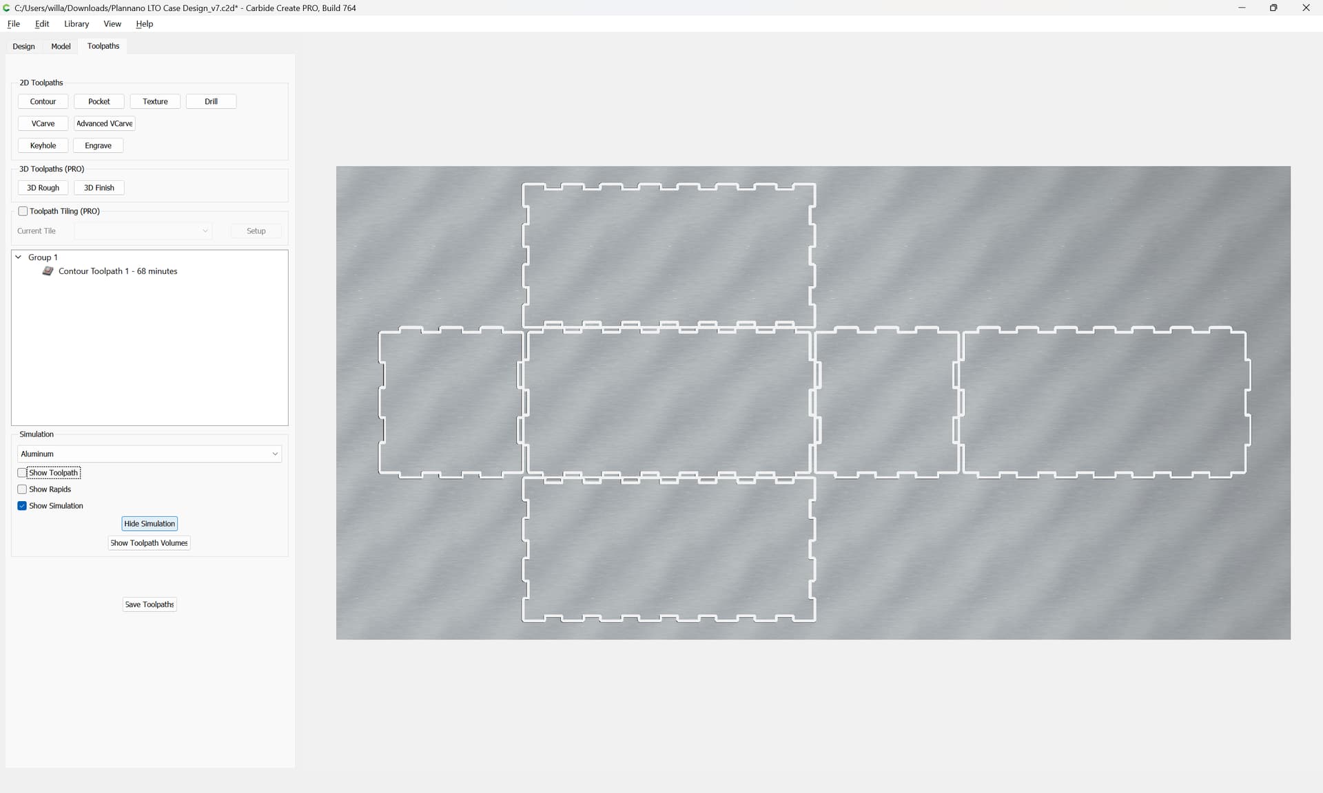
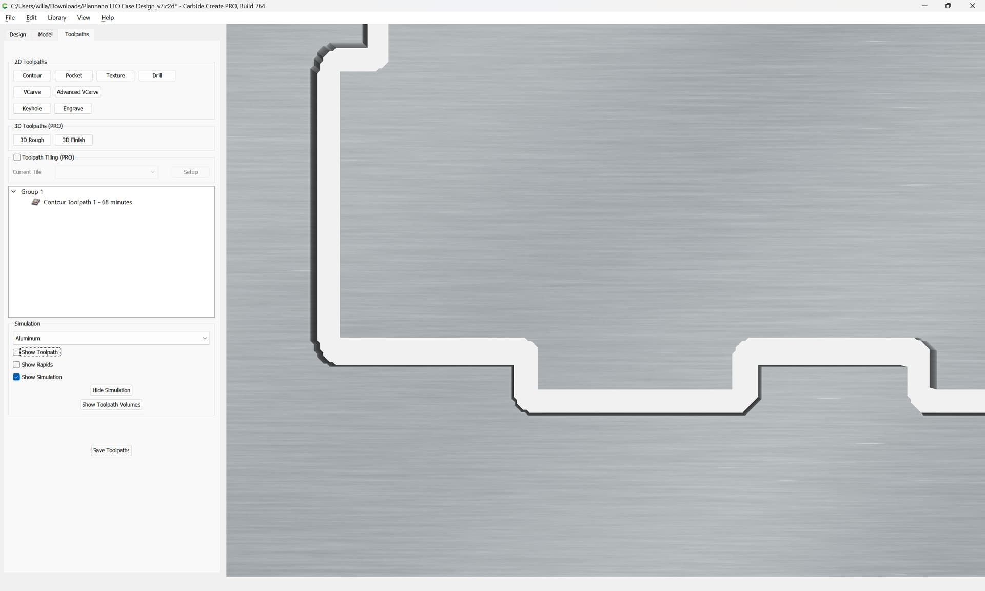
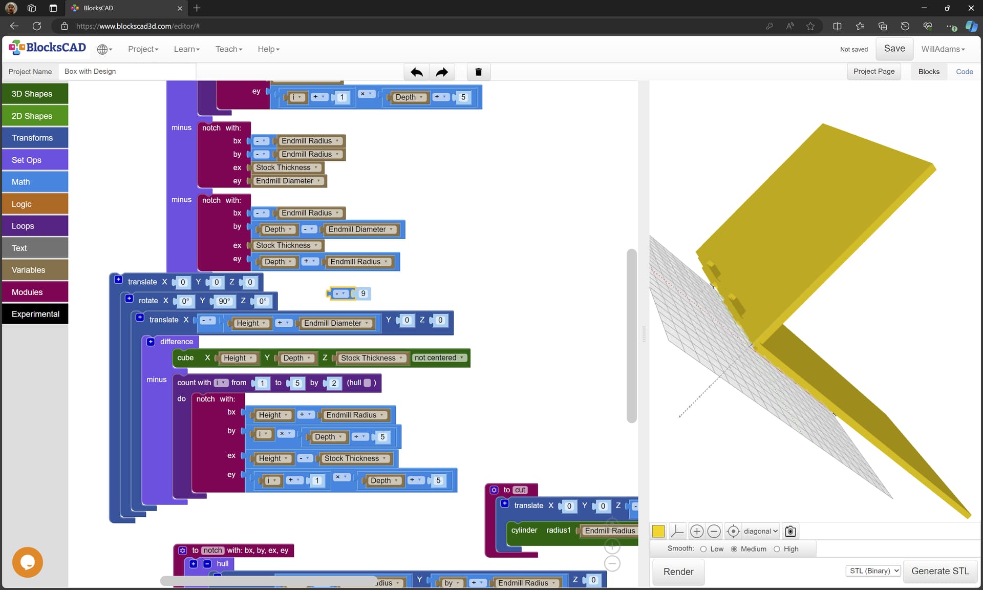
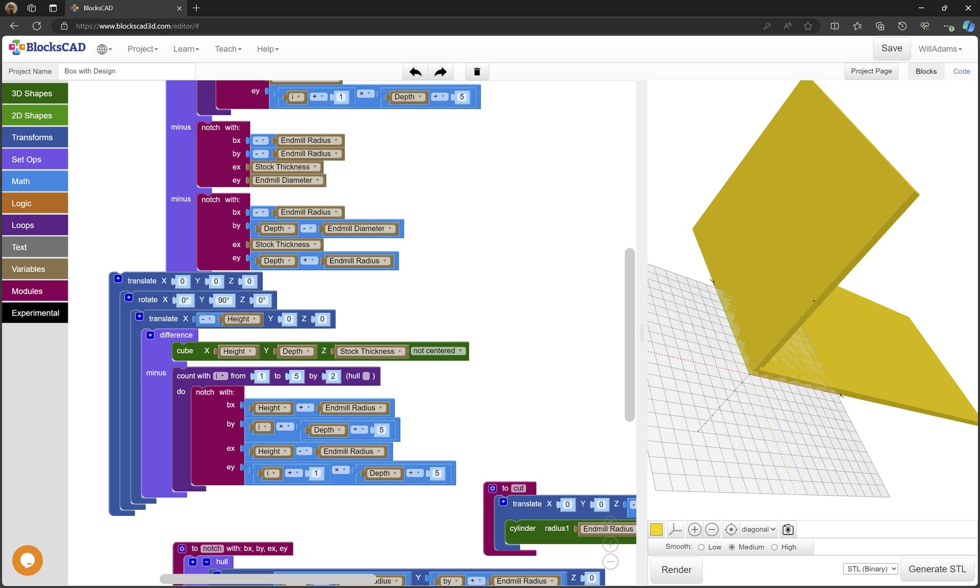
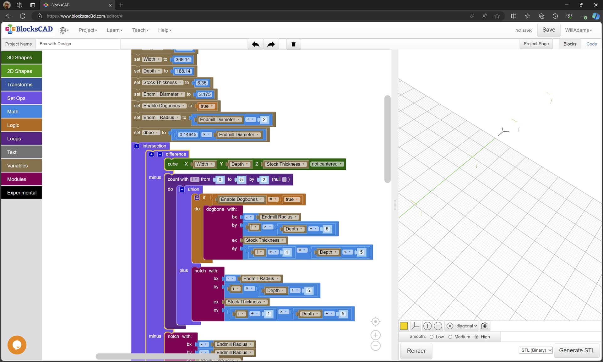
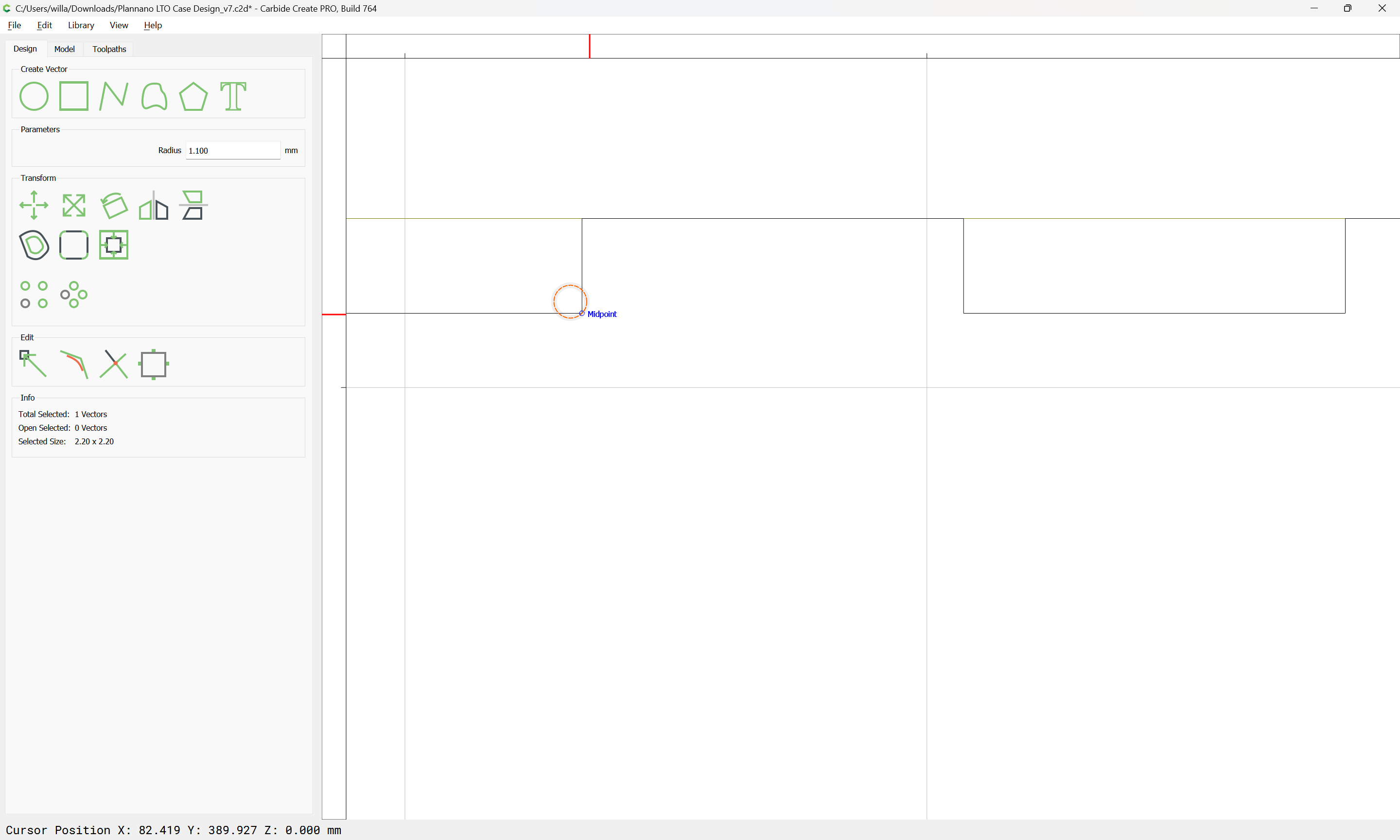
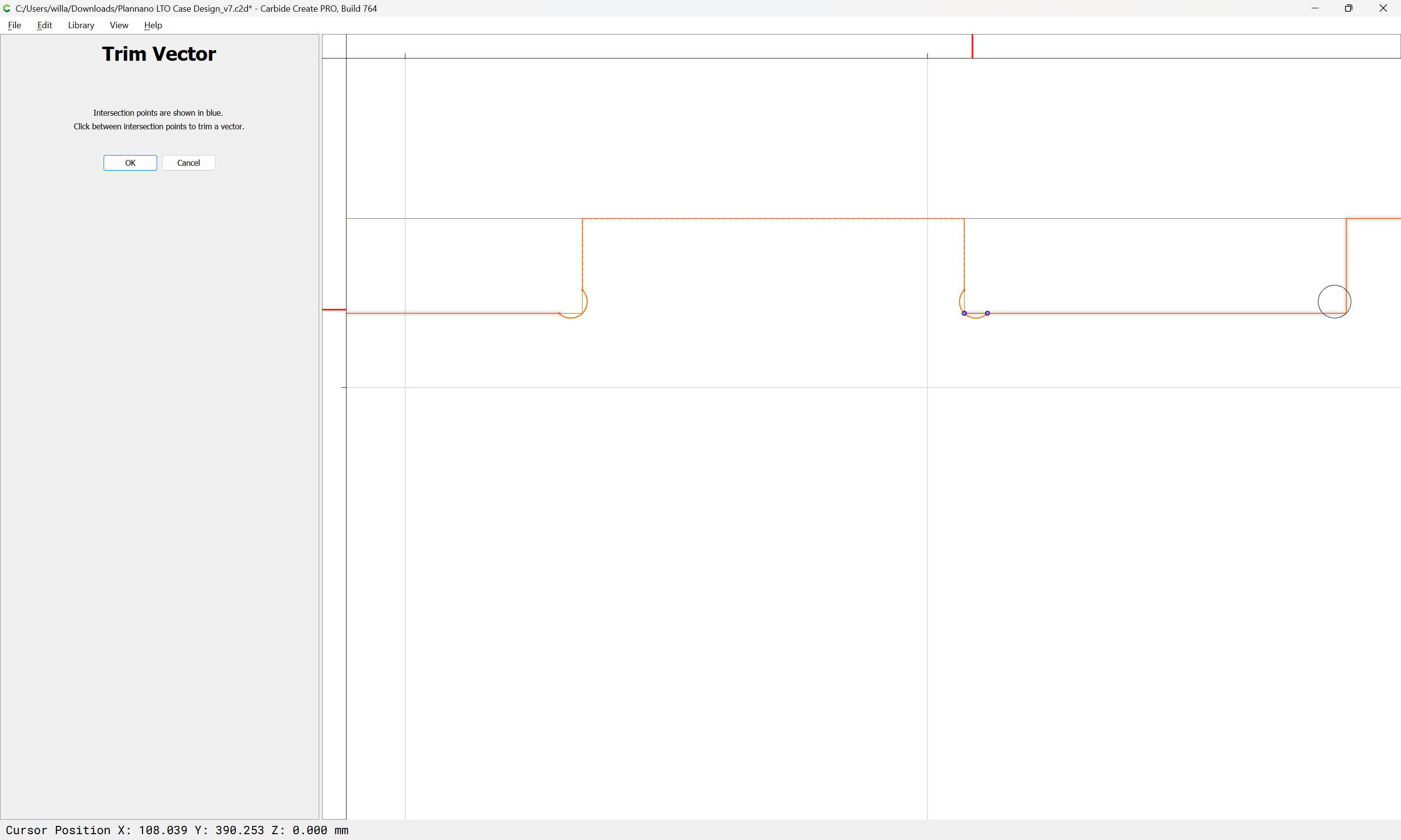
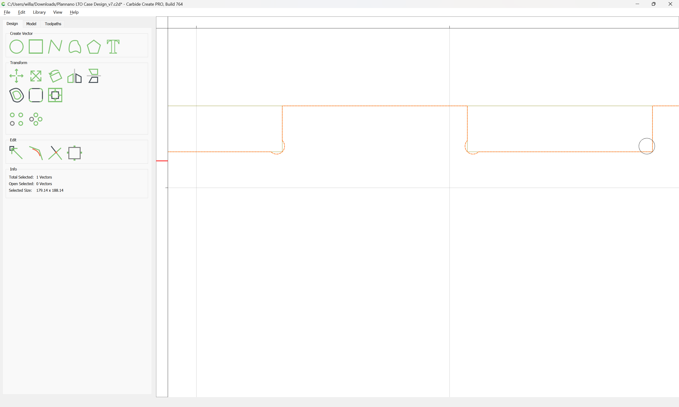
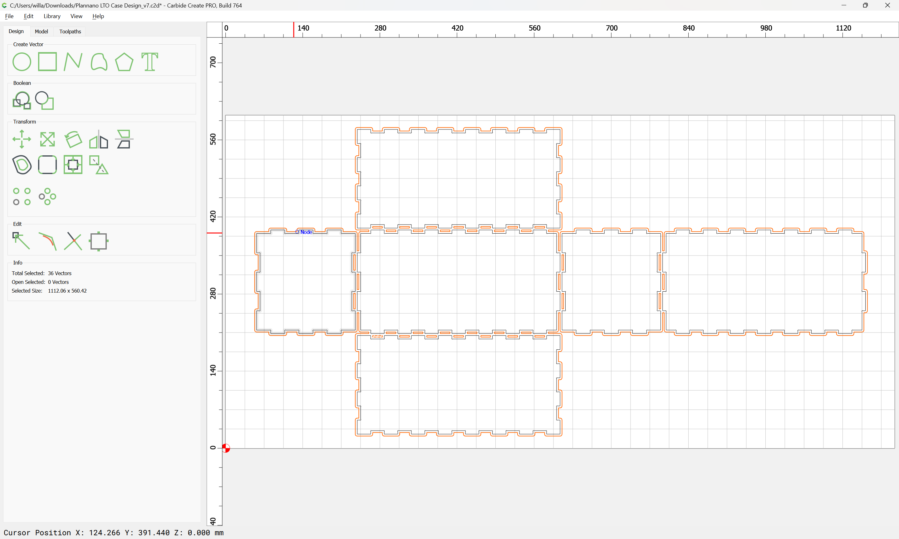
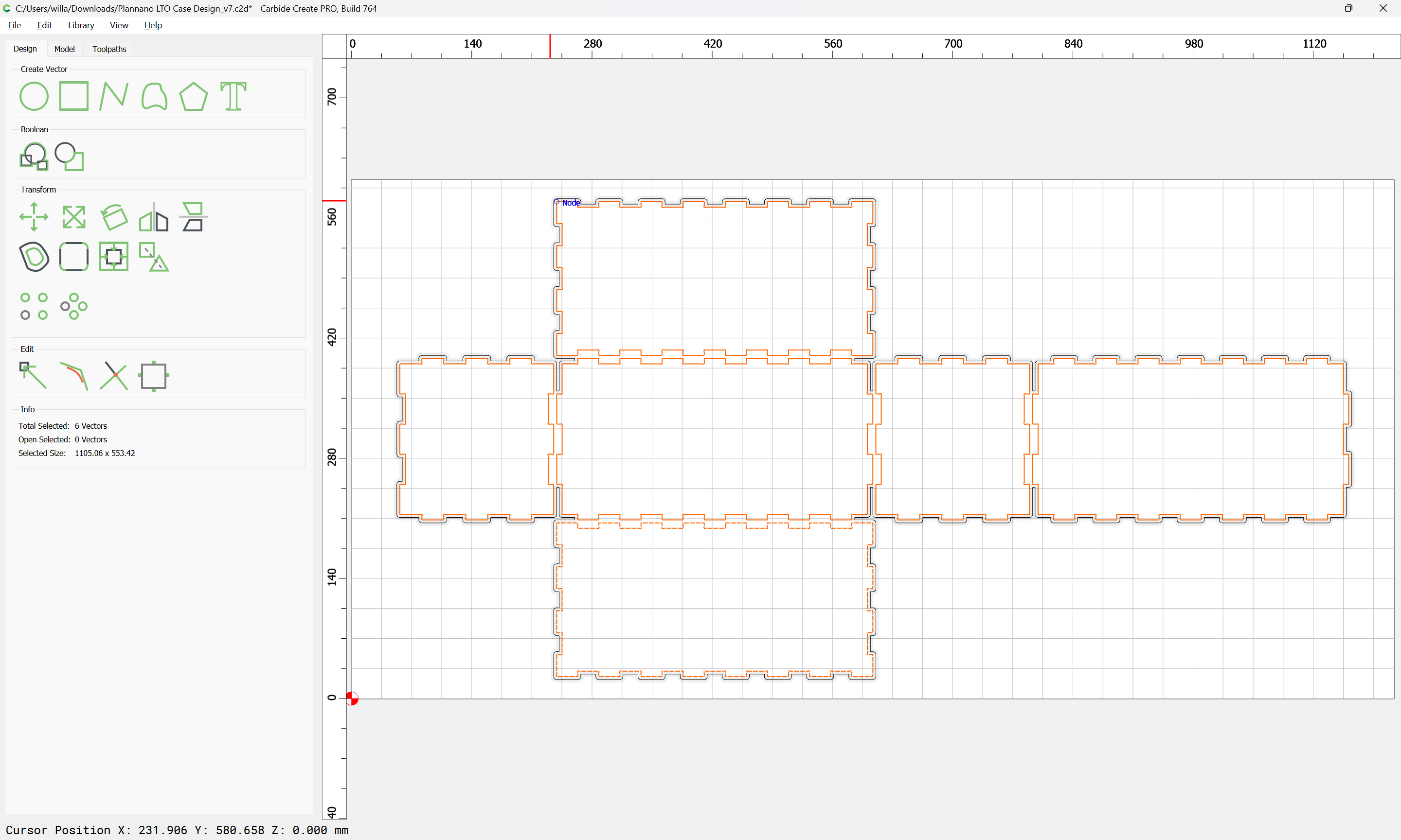
Next, each edge has to be notched for the box joints — note that this has to take into account the physical structure of the box and how the stock thickness interacts with the size of the joint projections.
to create the joints, I’ve divided the length by 15, width by 7 and height by 5.
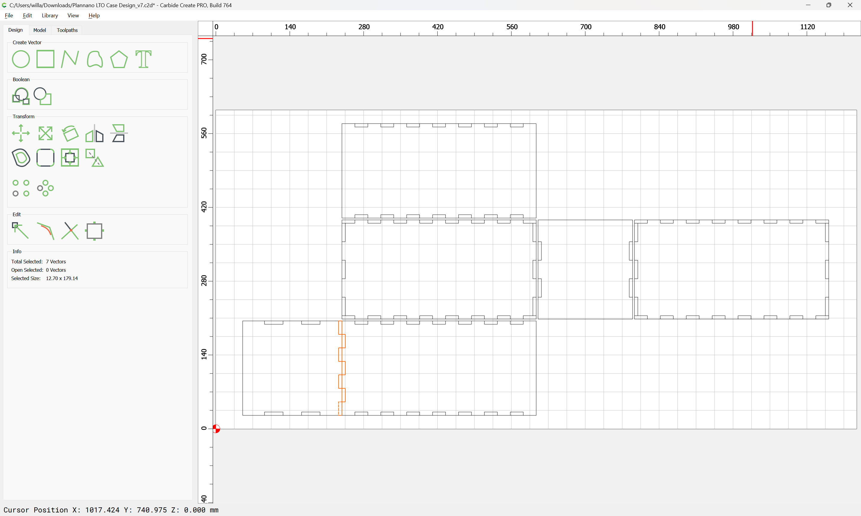
Looking at the image, the front has full-length divisions.
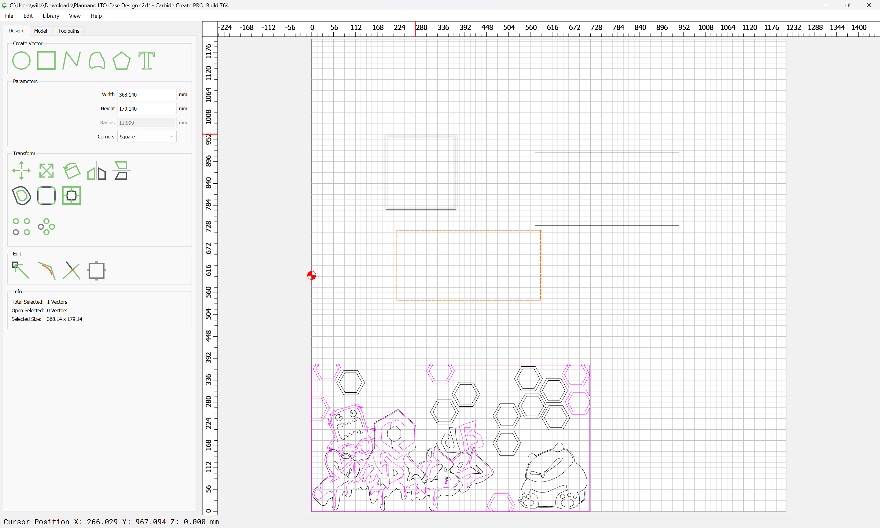
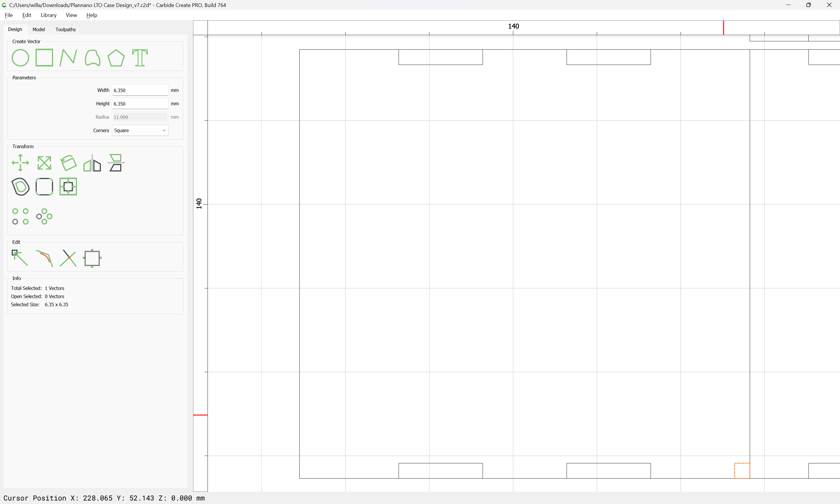
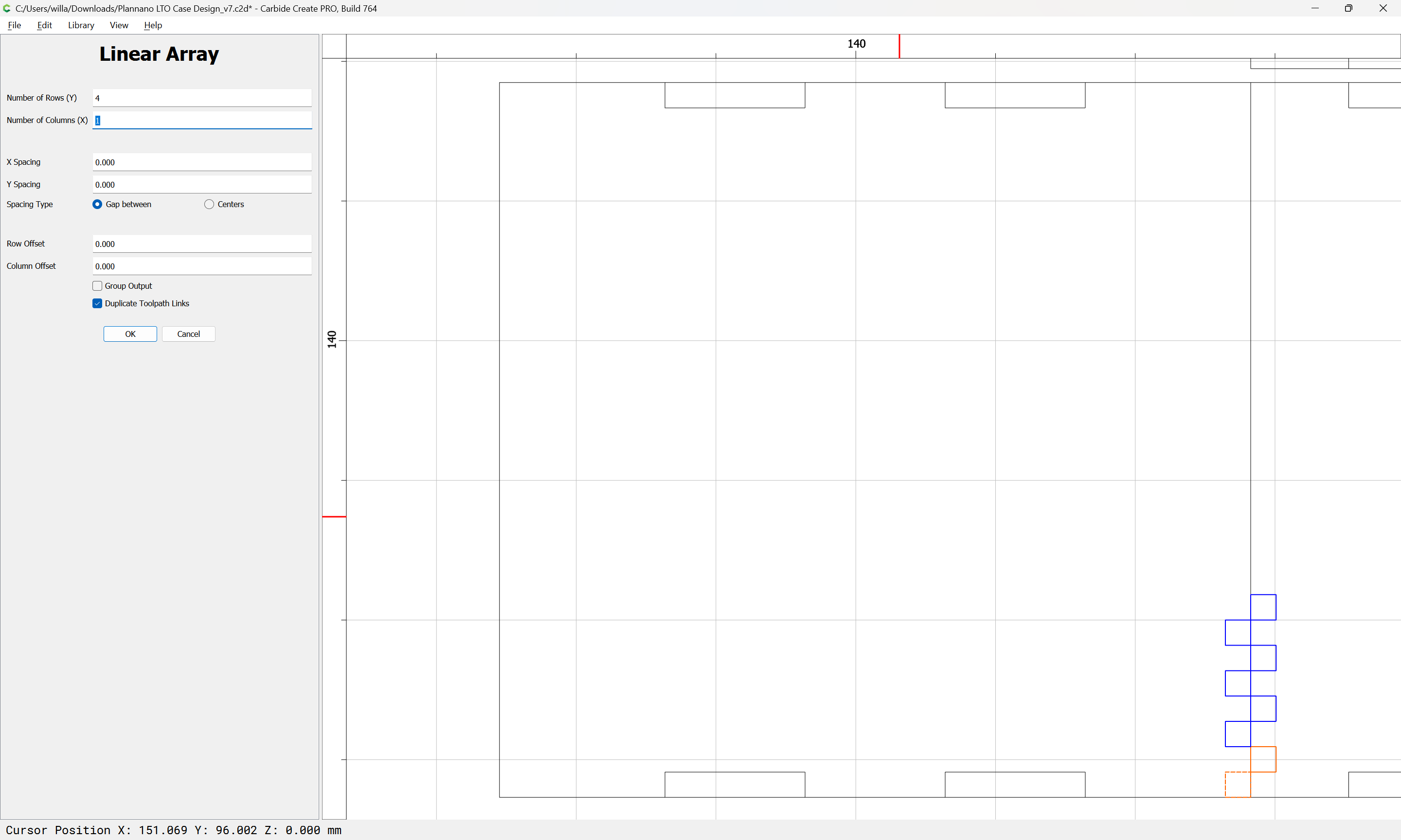
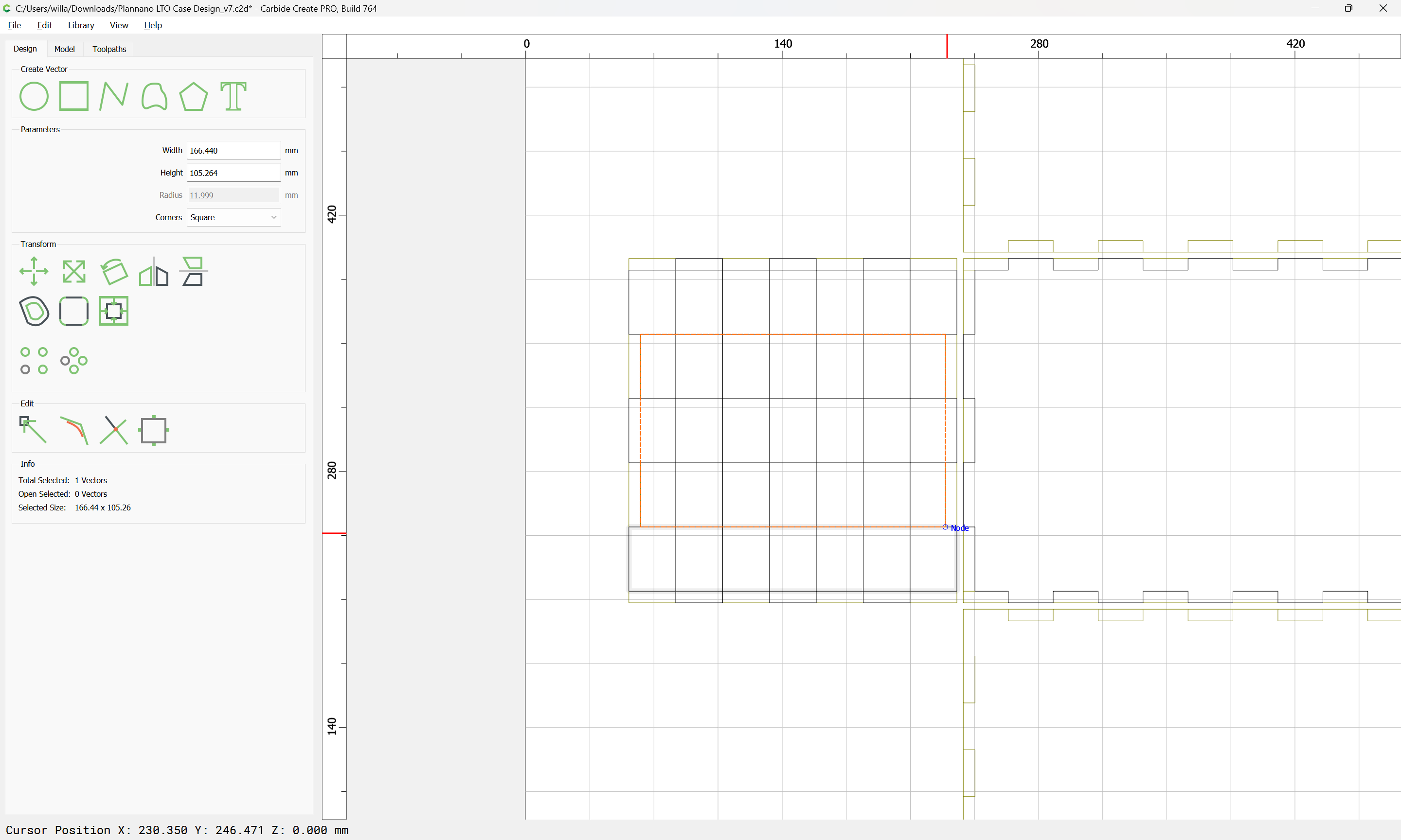
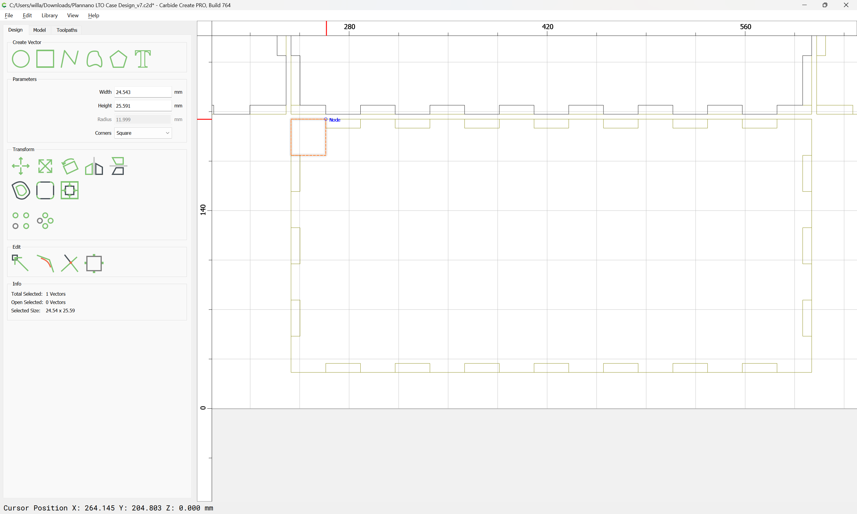
In theory, one could create a rectangle the size of the long dimension, divide it by 15, then use the Linear Array tool to replicate it as needed, but in practice, rounding issues keep things from lining up.
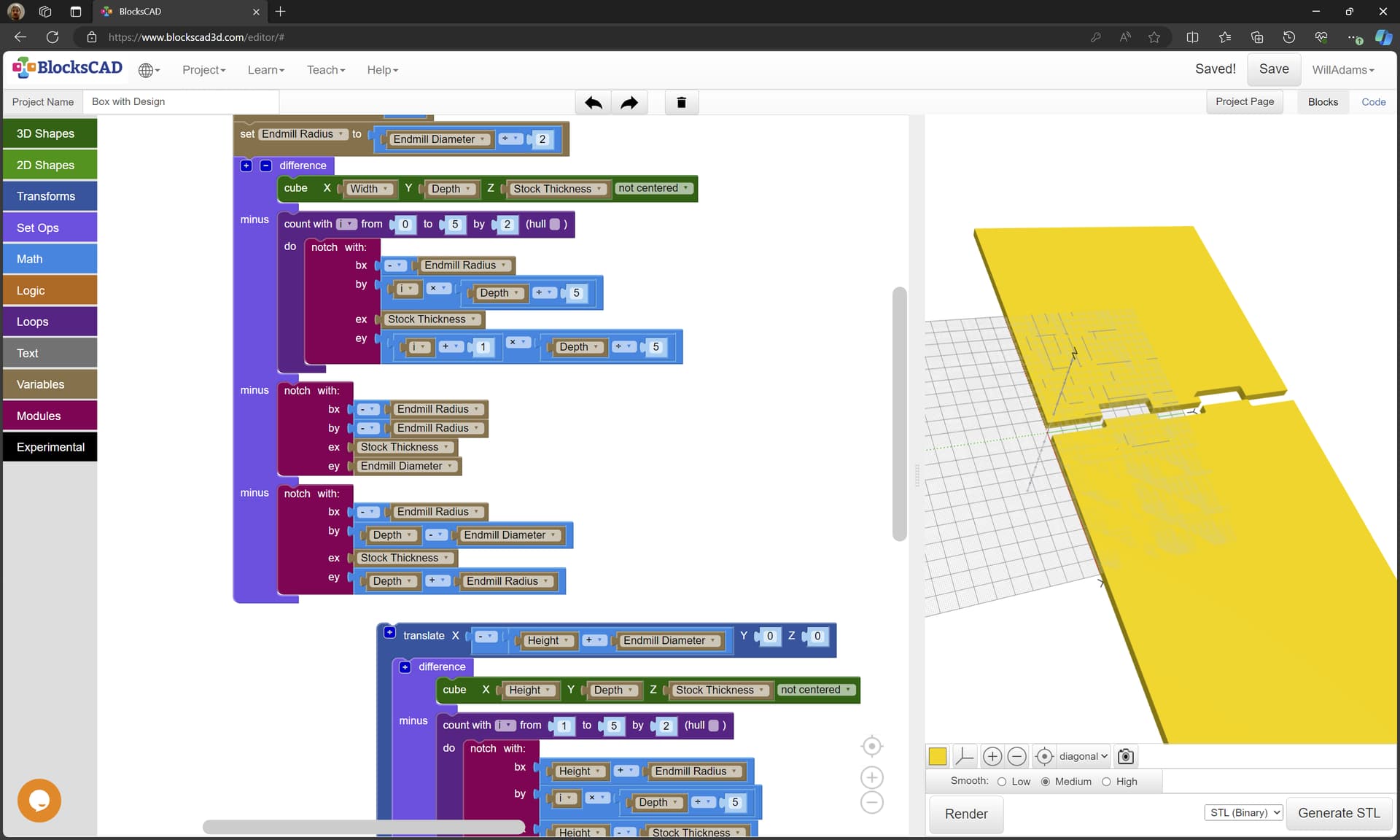
A further consideration is that there are various online or other utilities for making such boxes such as:
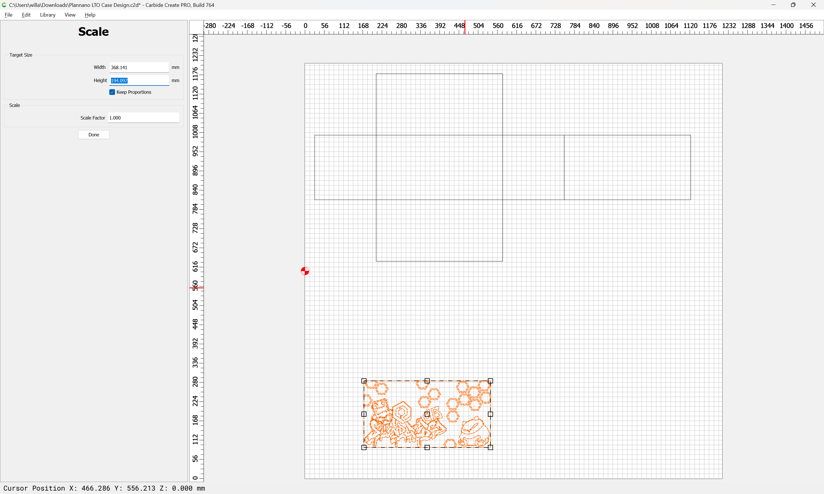
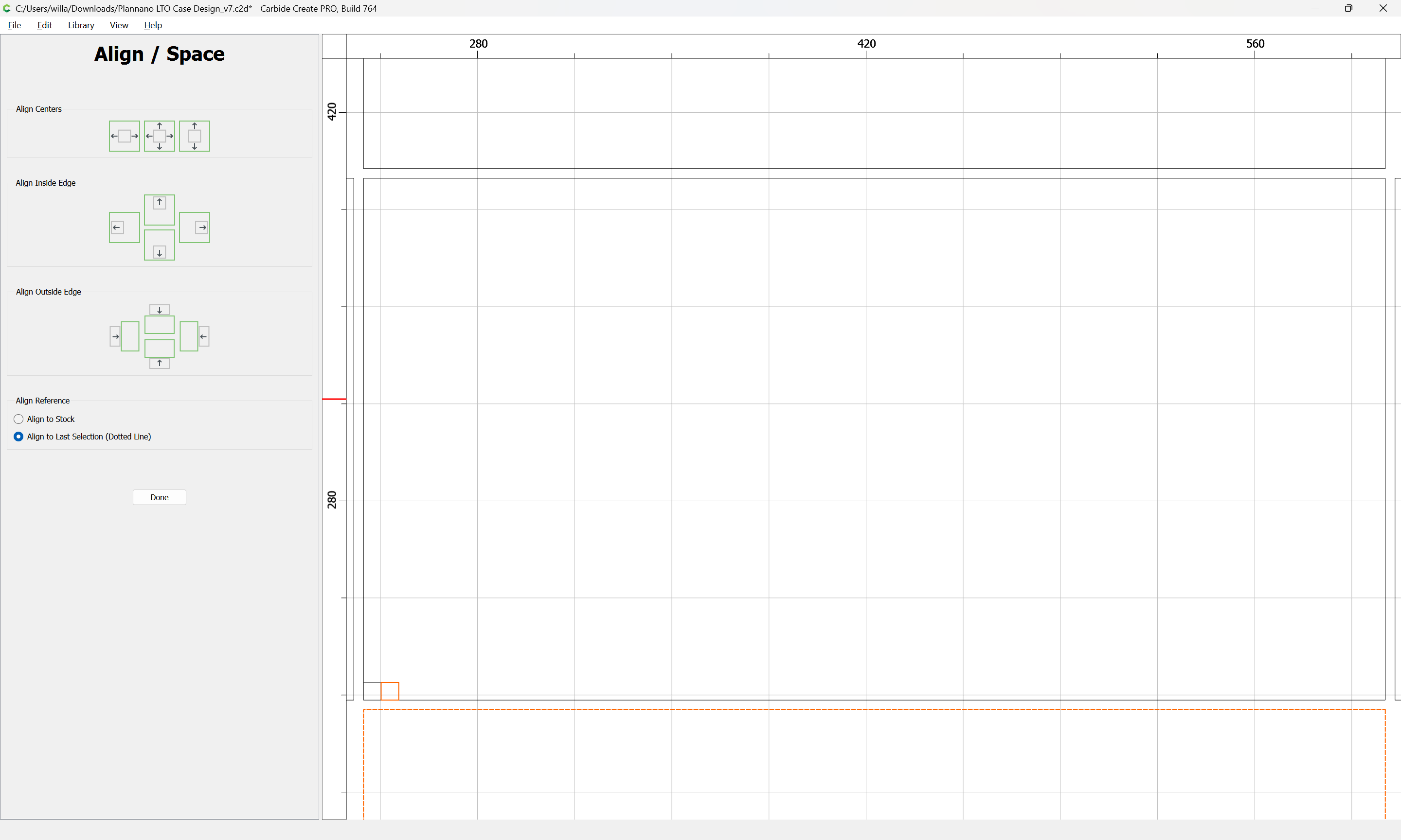
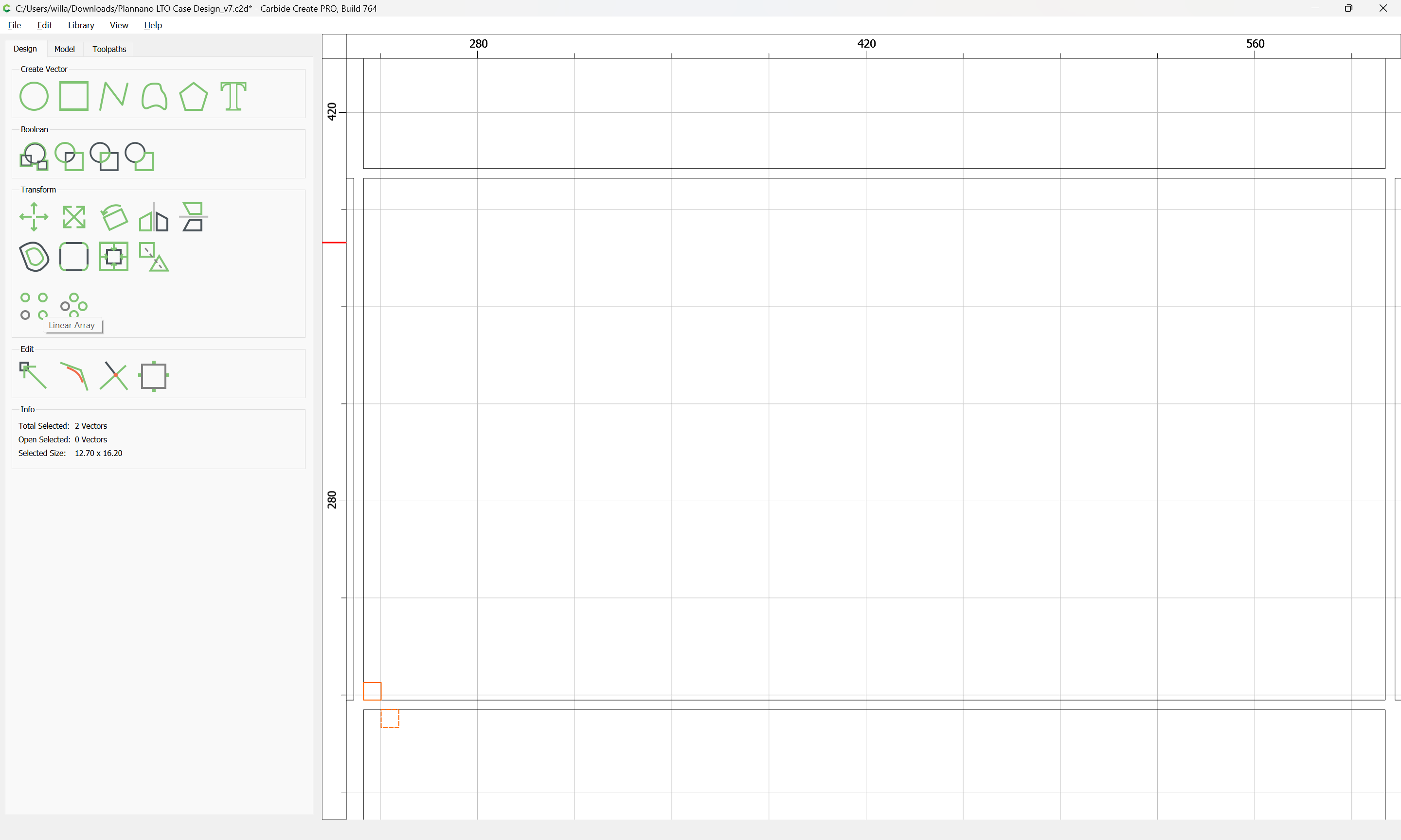
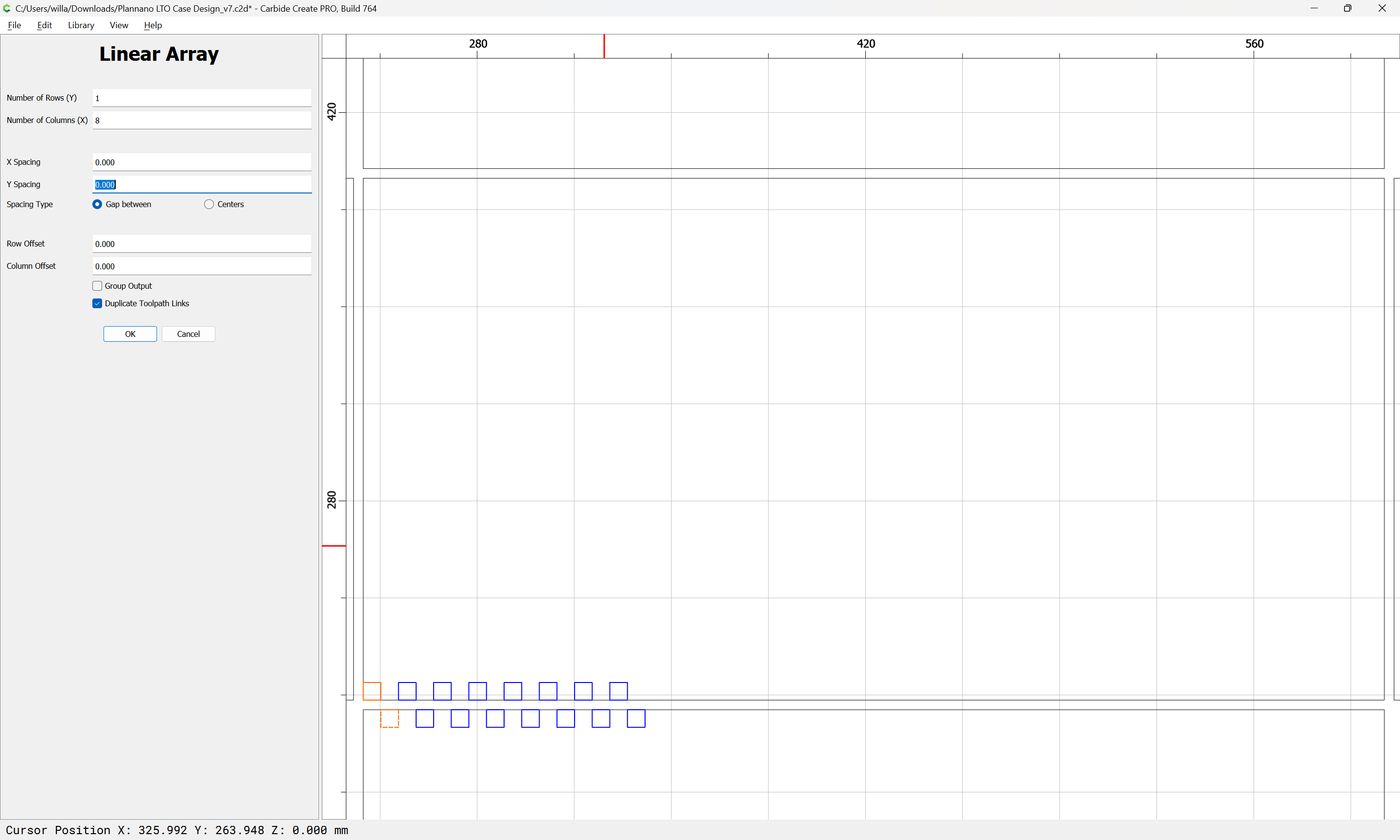
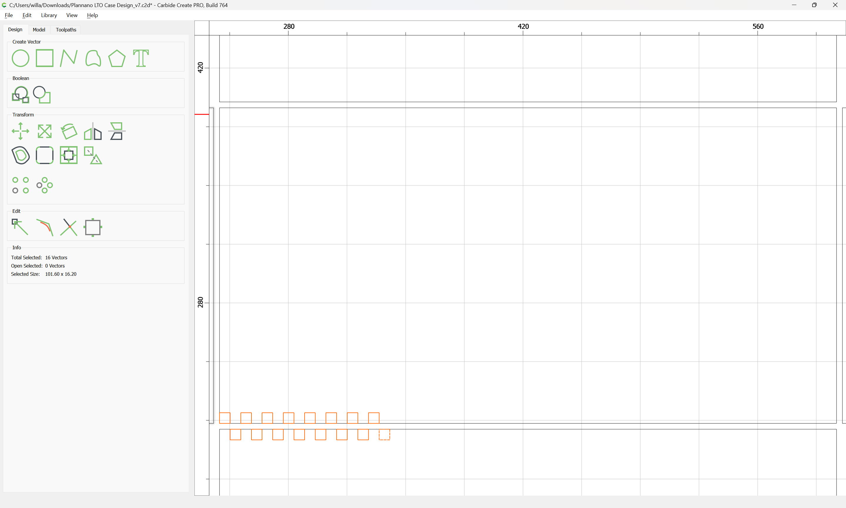
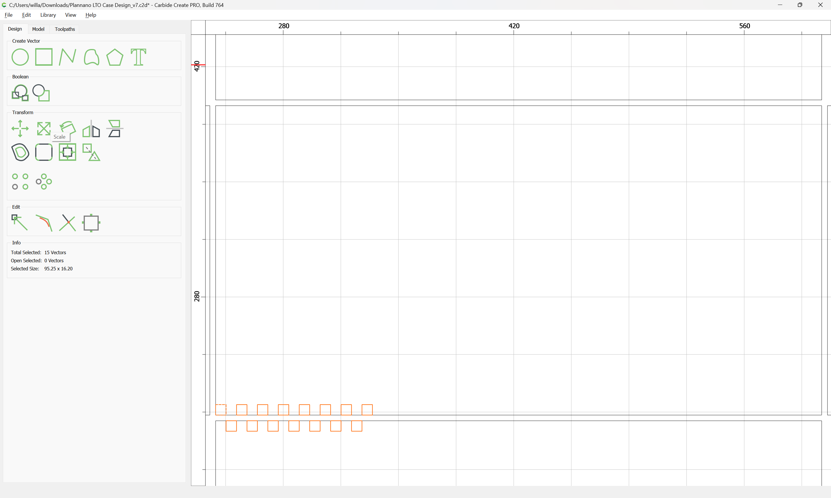
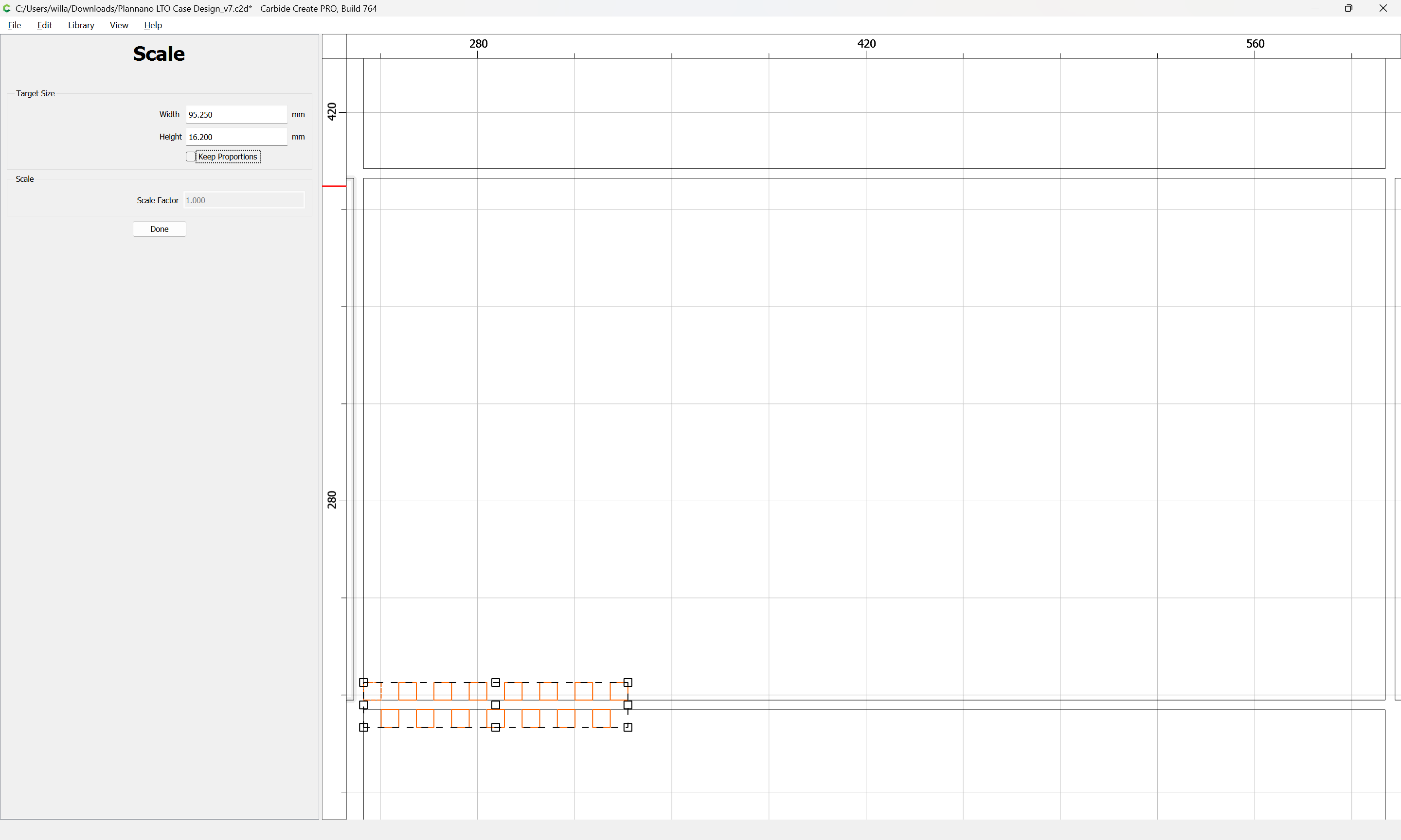
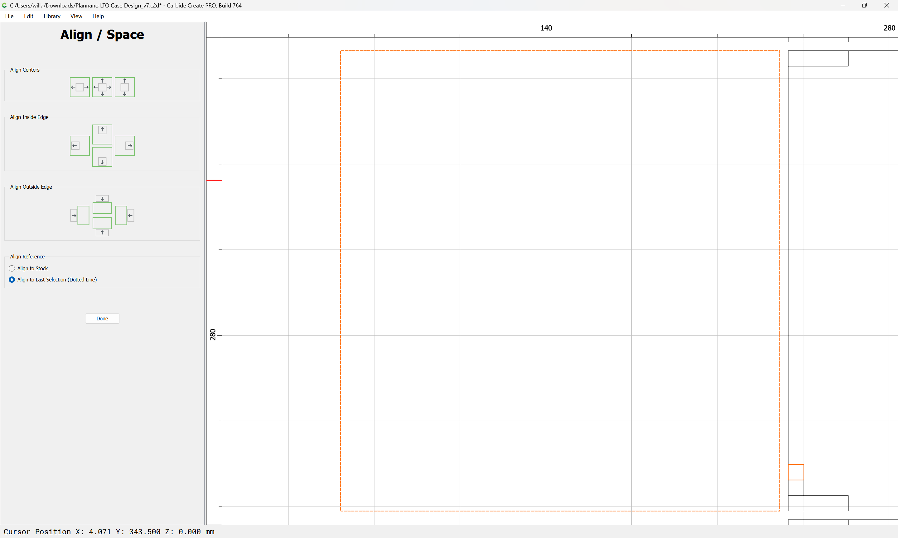
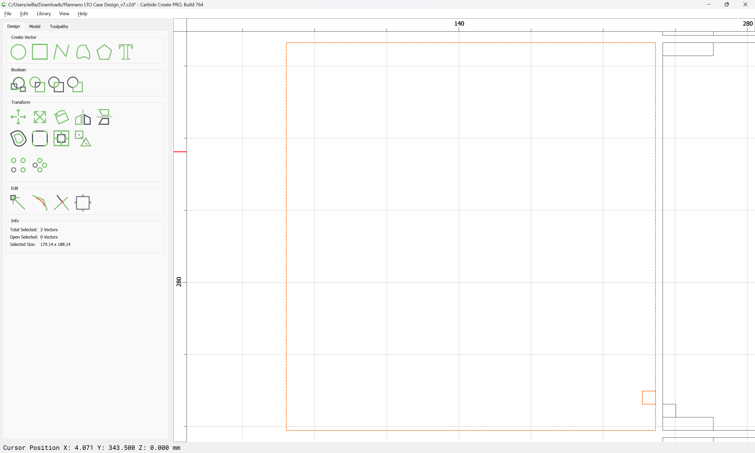
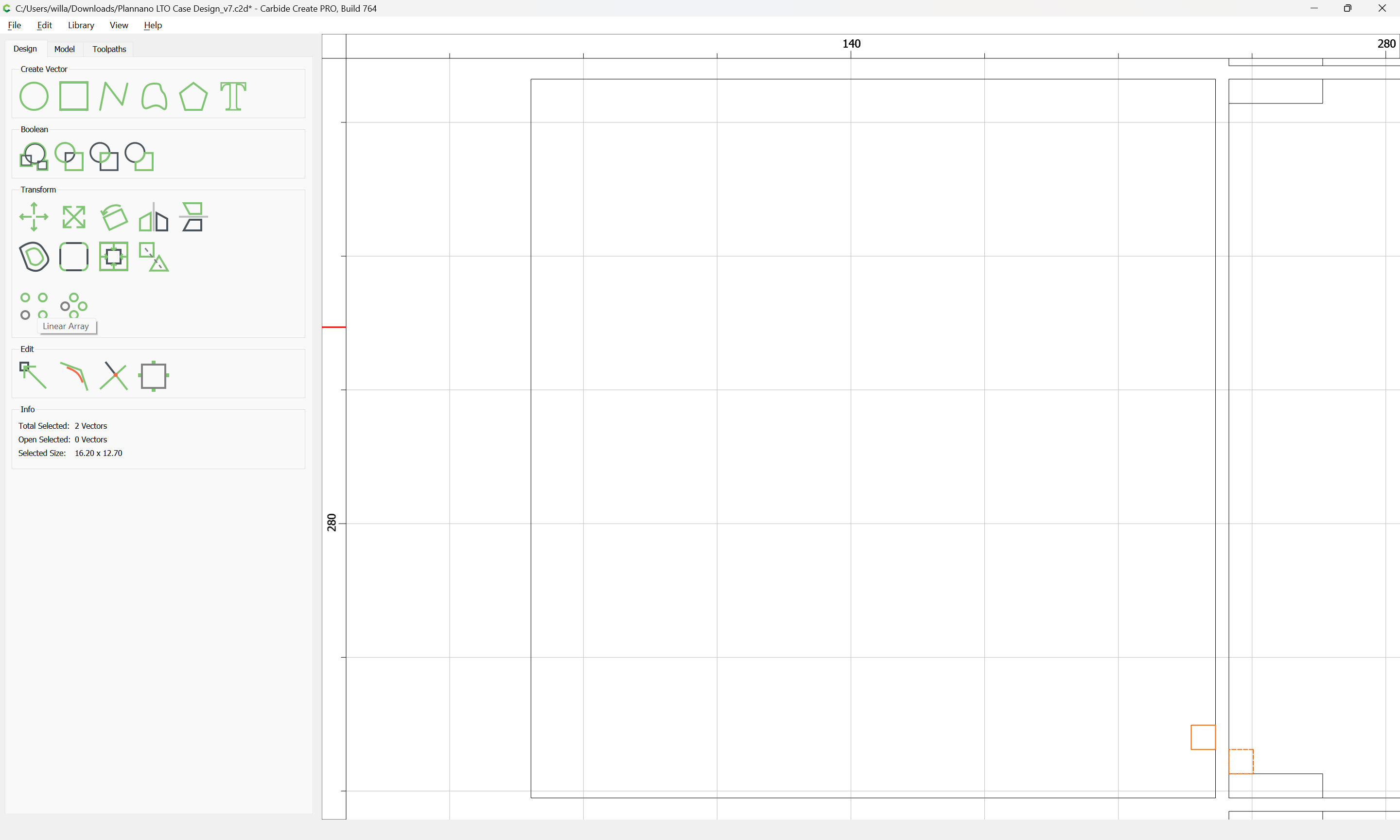
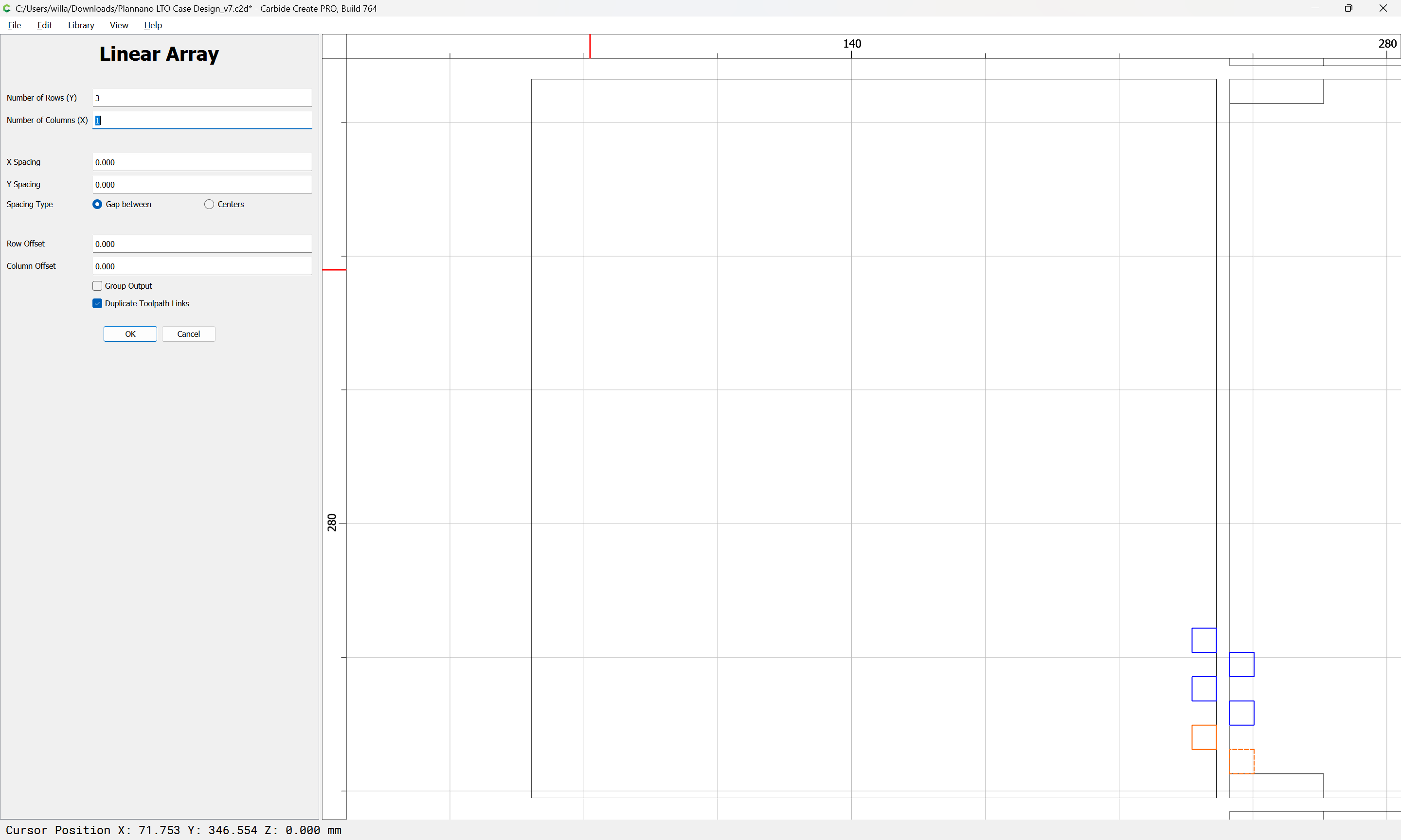
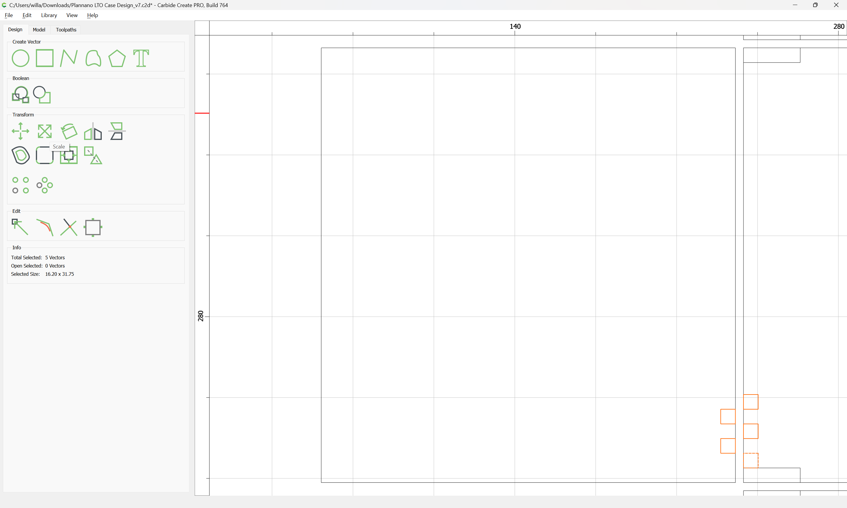
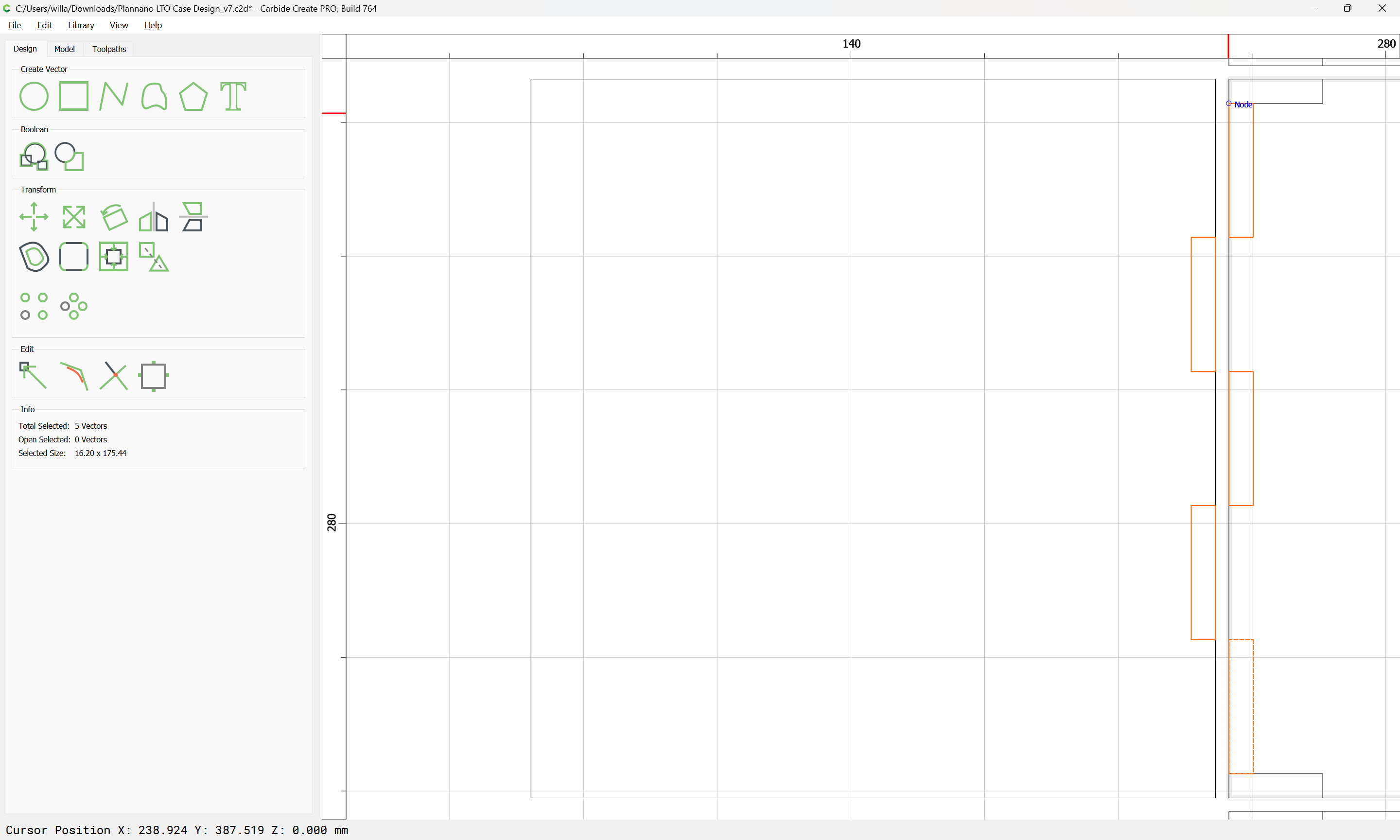
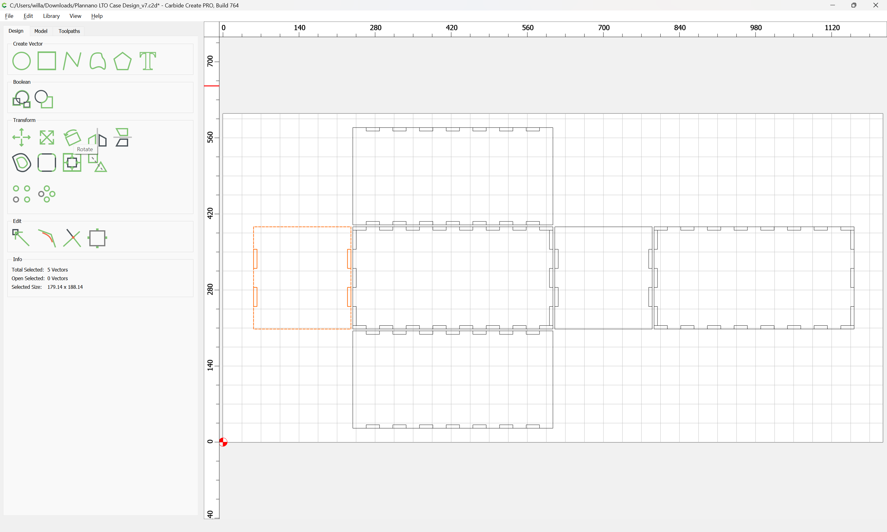
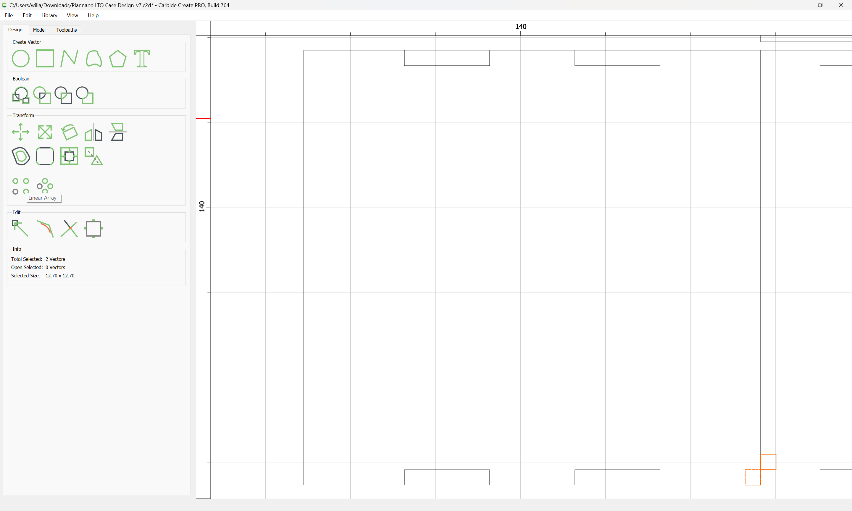
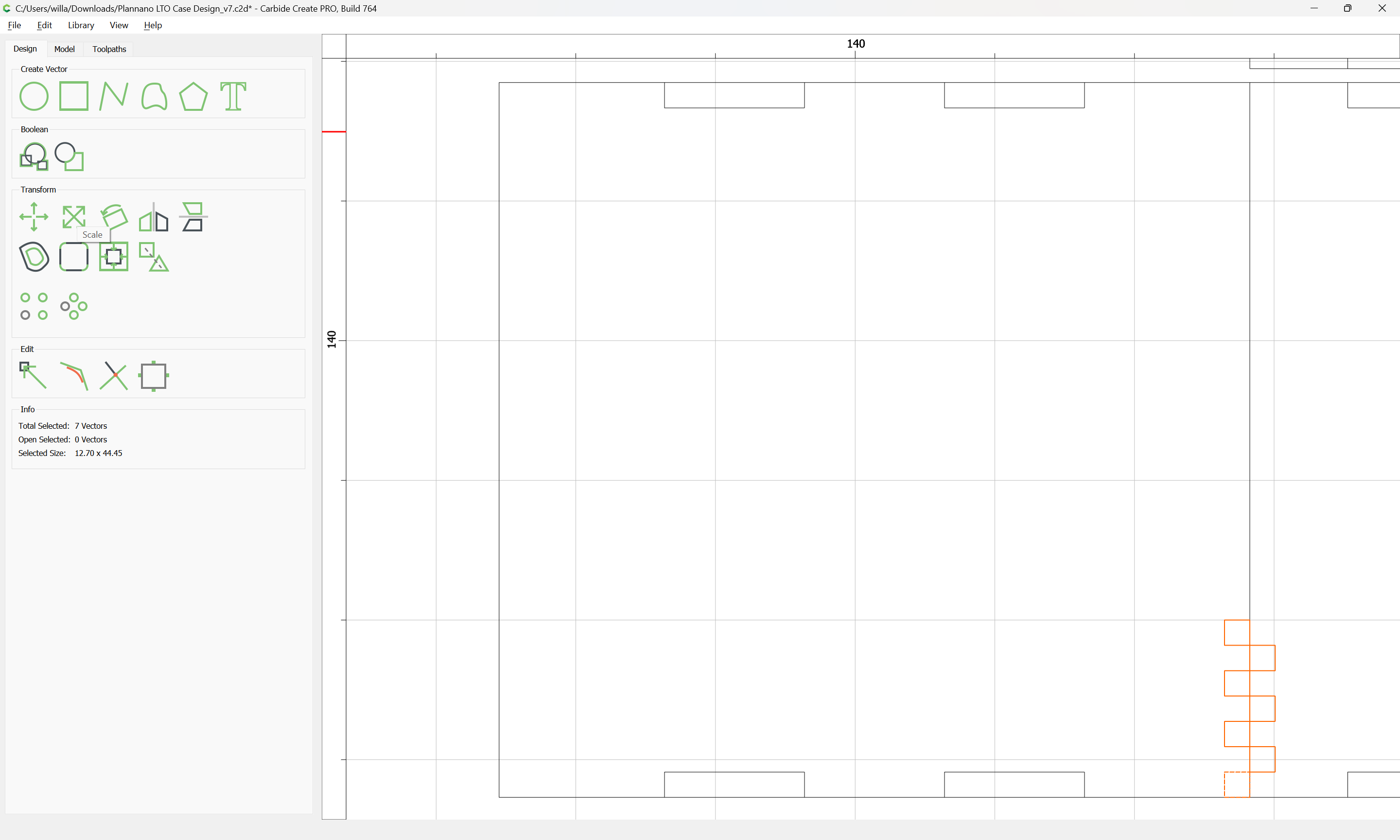
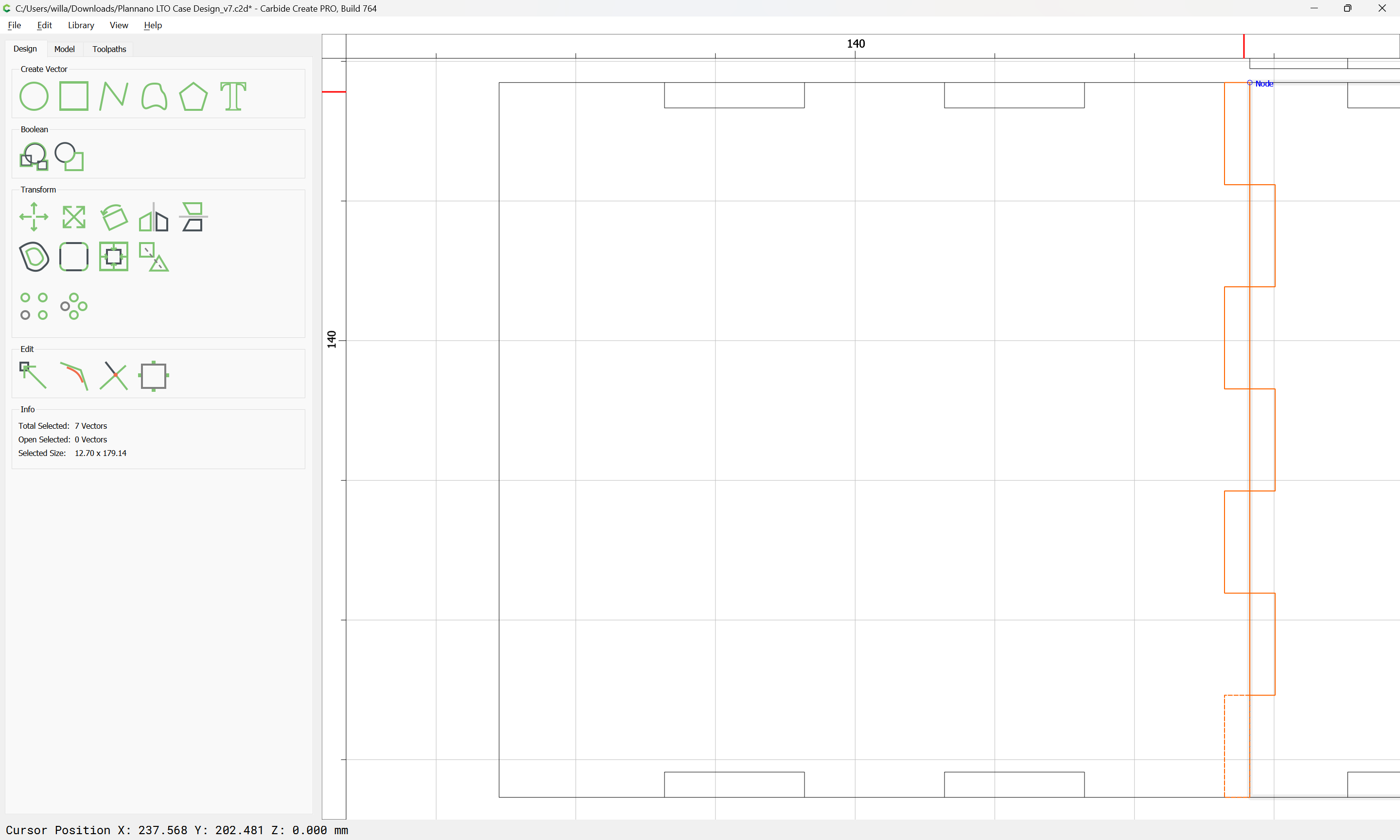
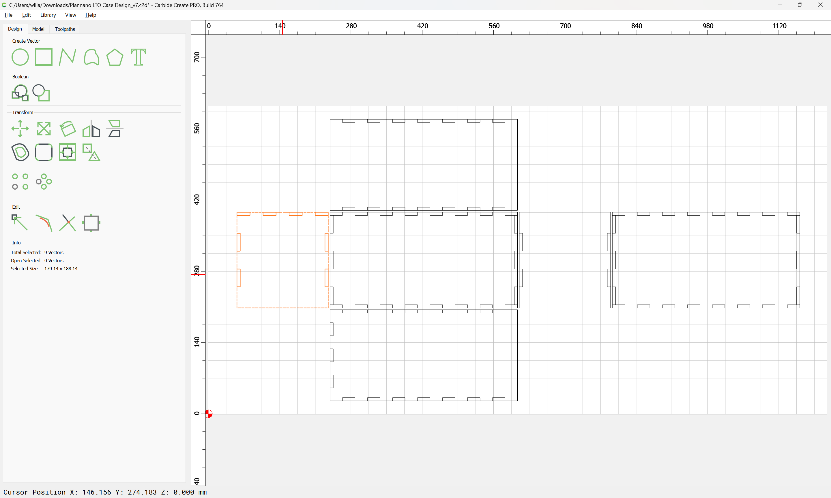
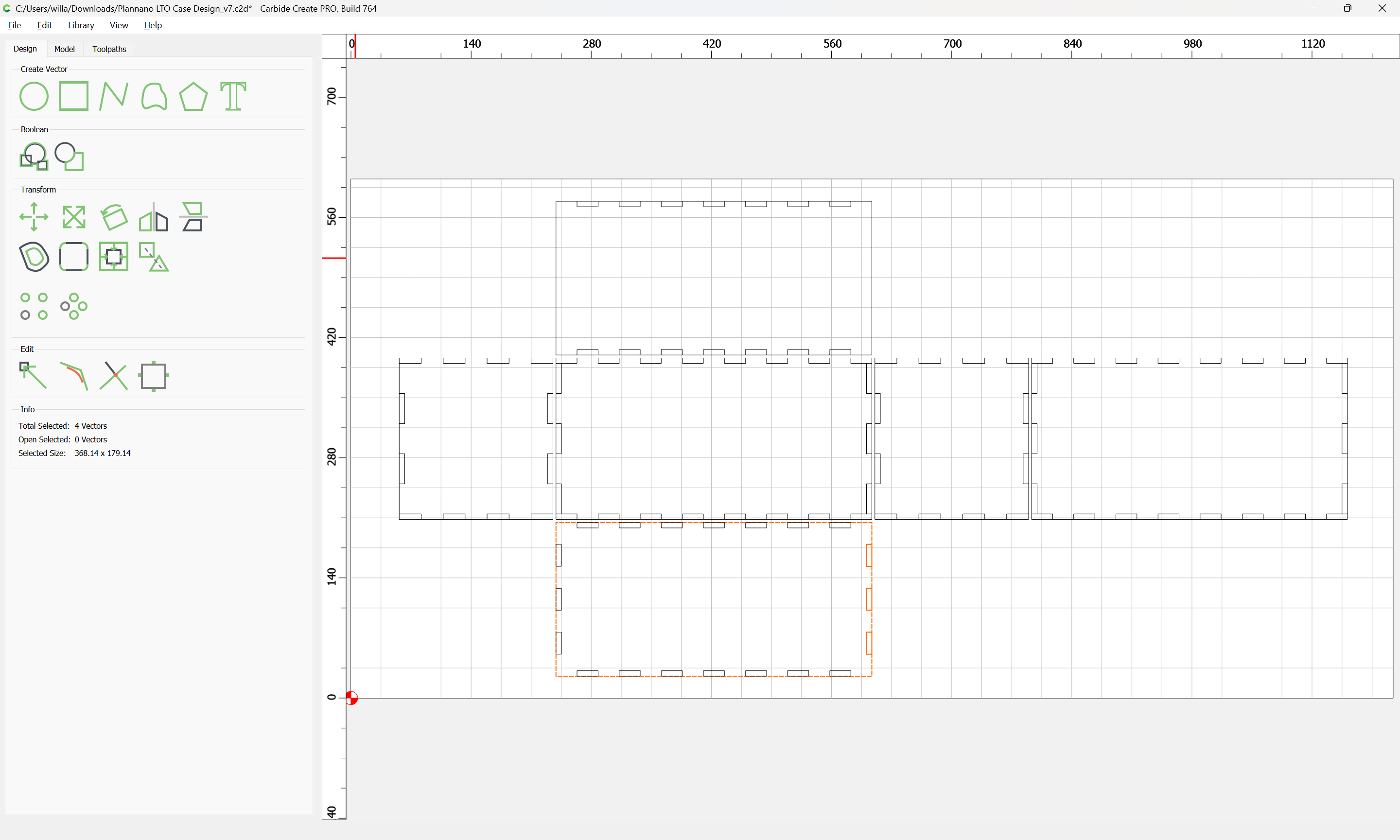
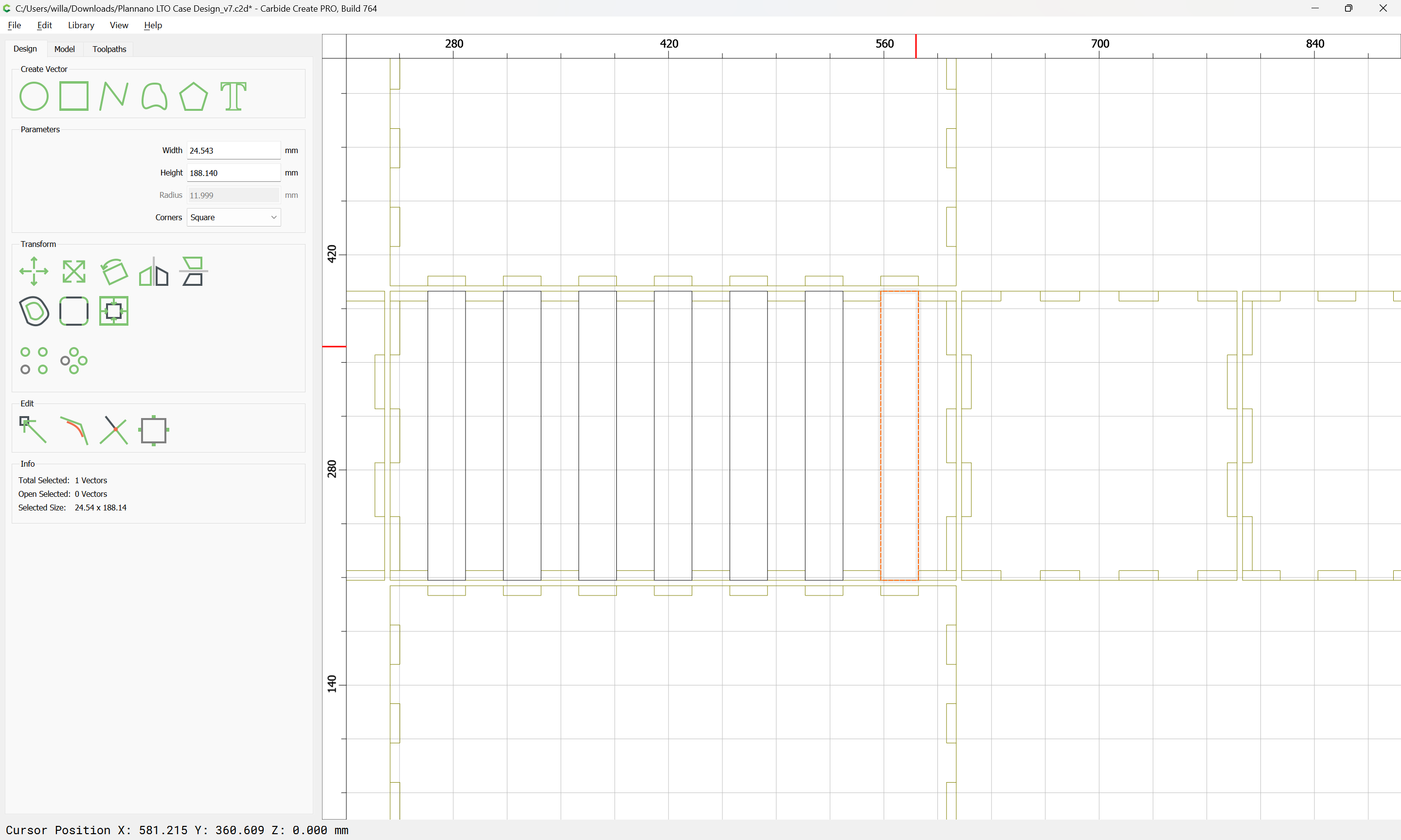
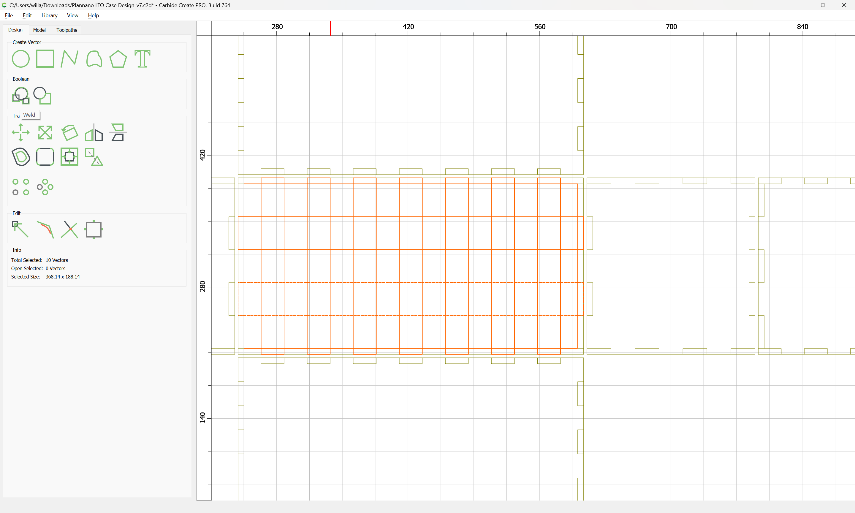
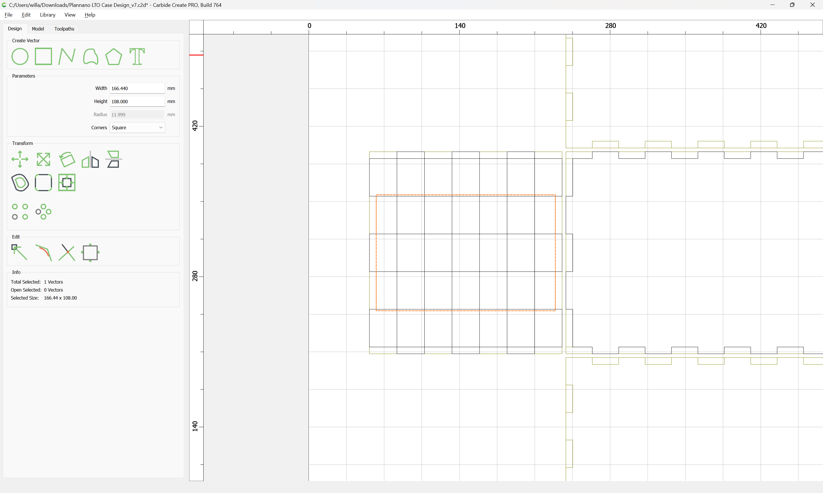
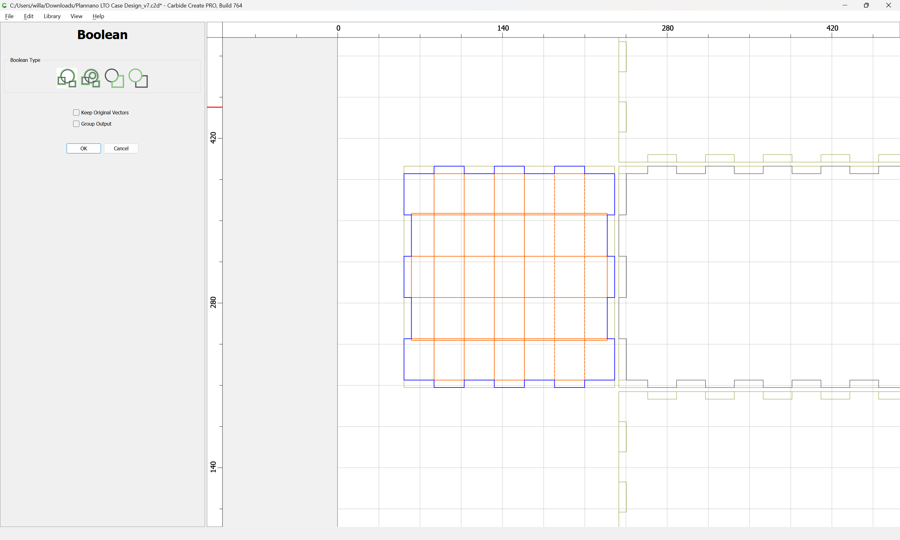
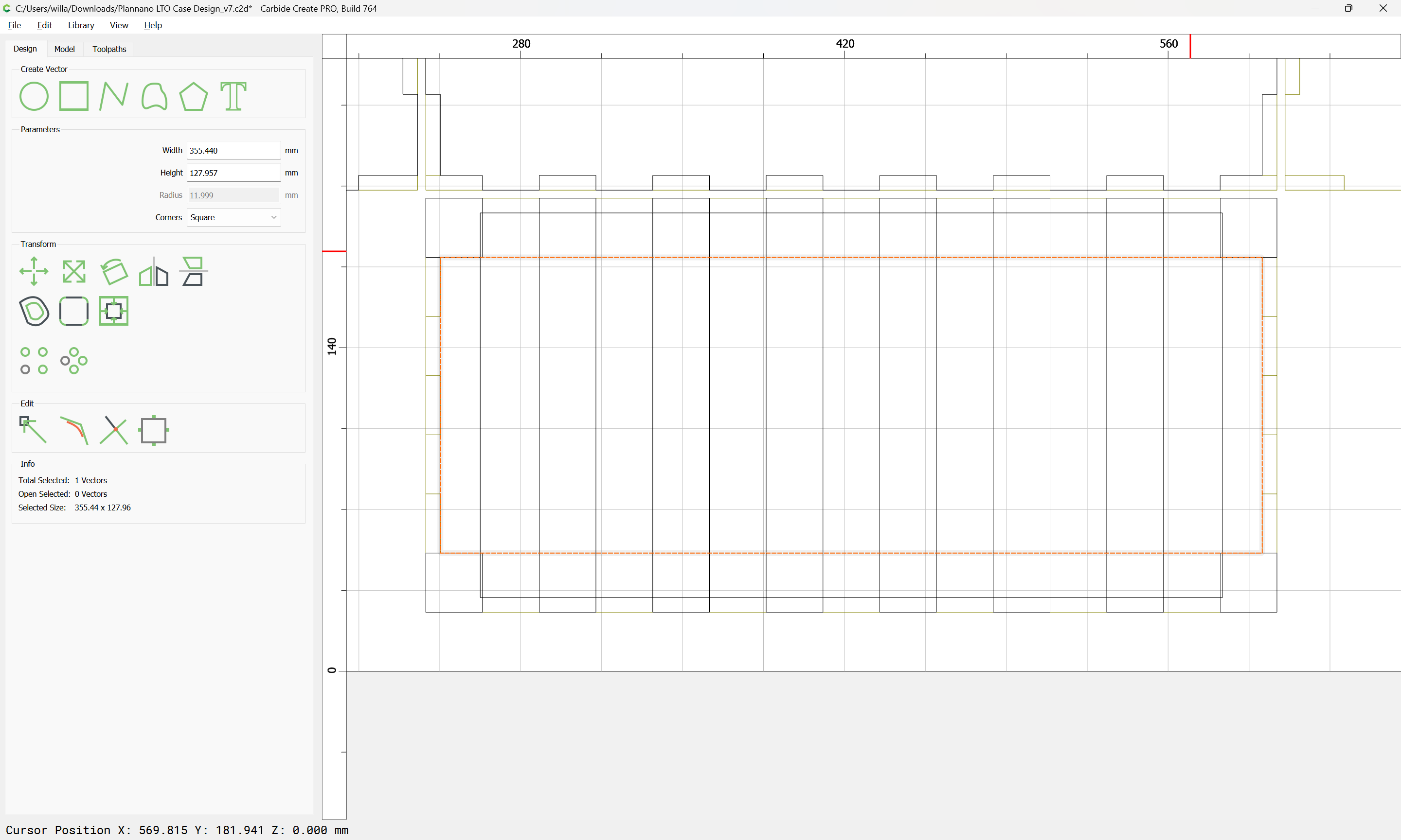
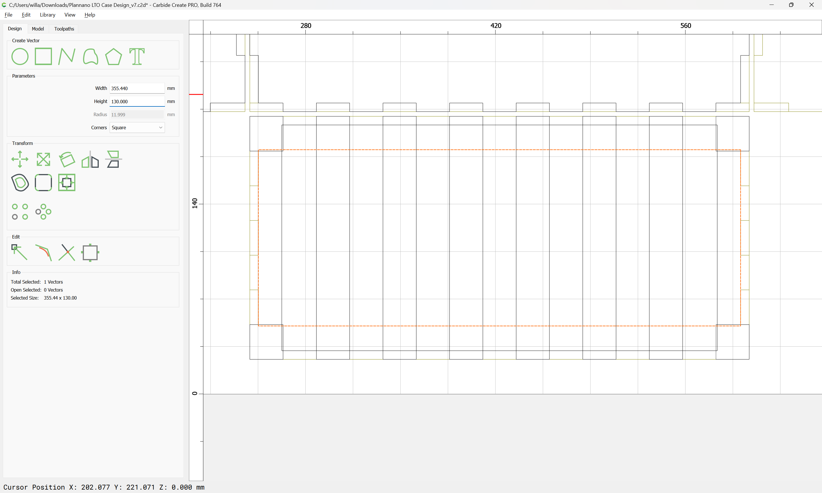
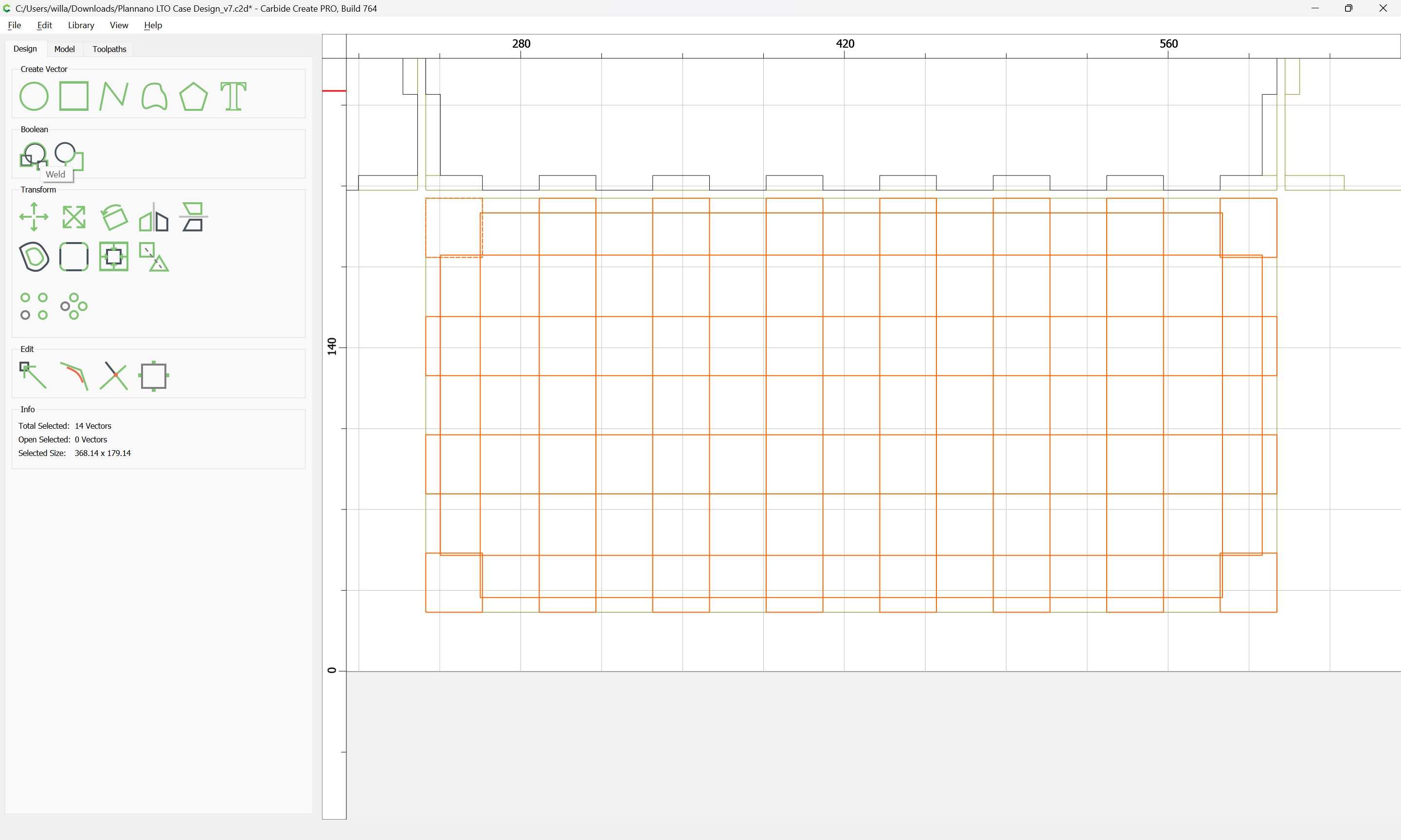
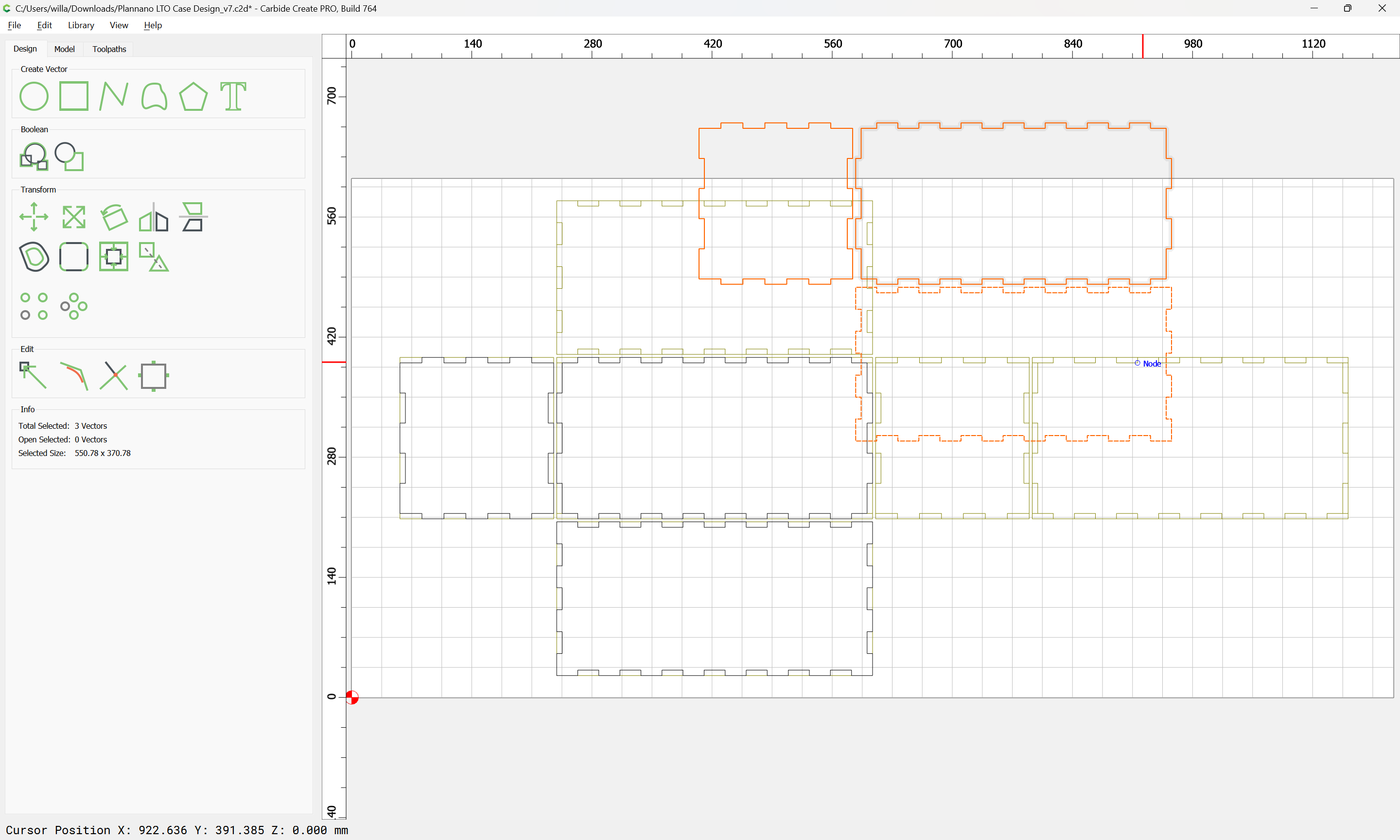
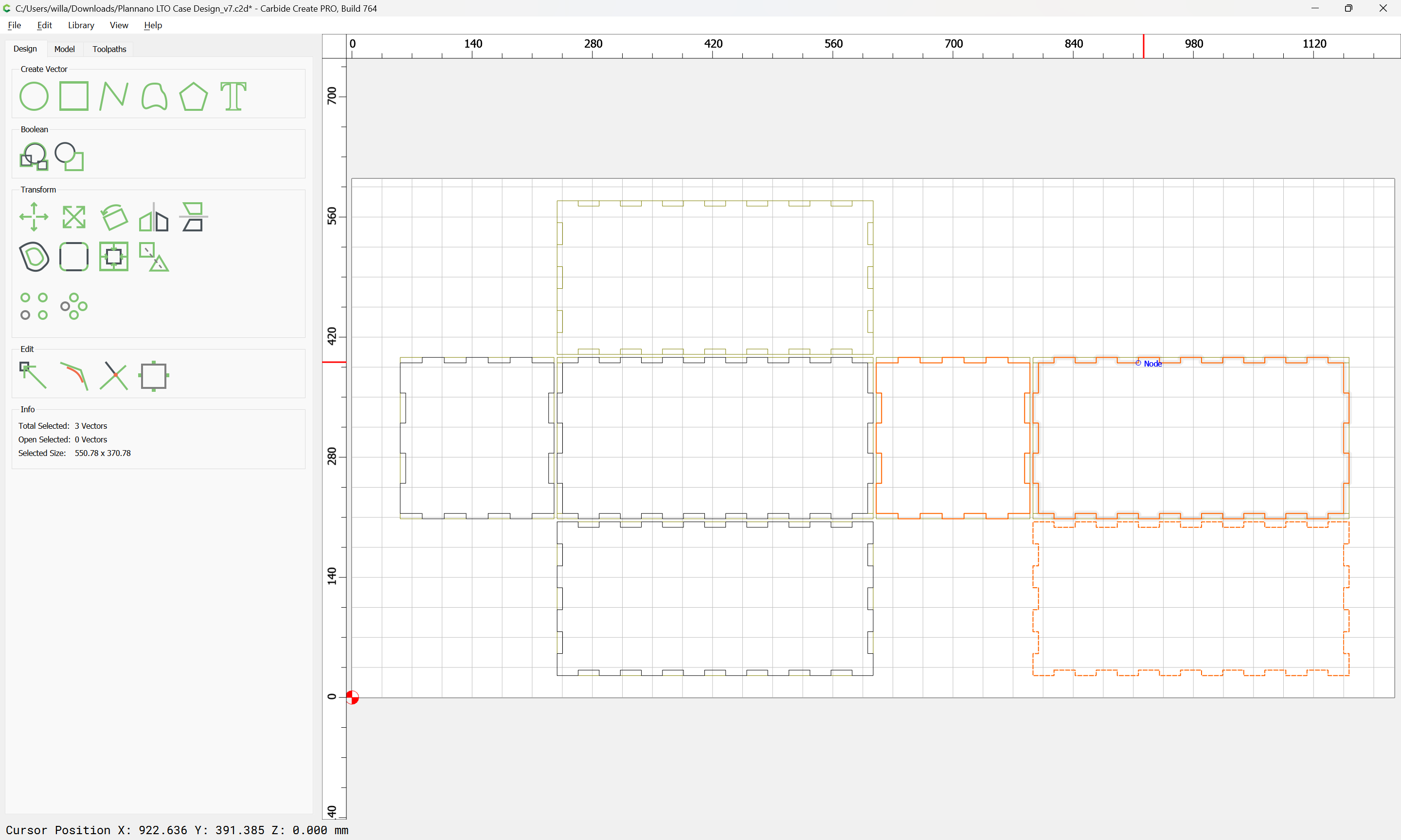
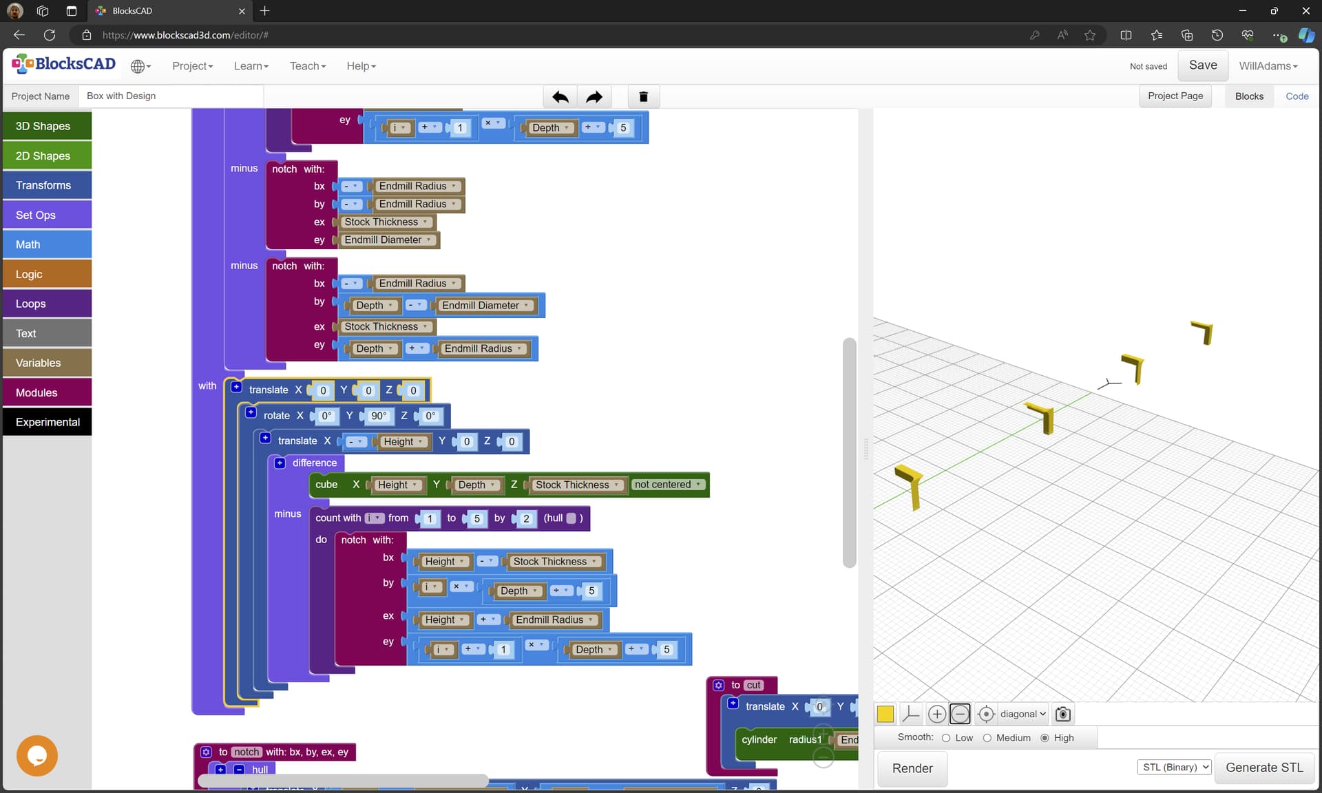
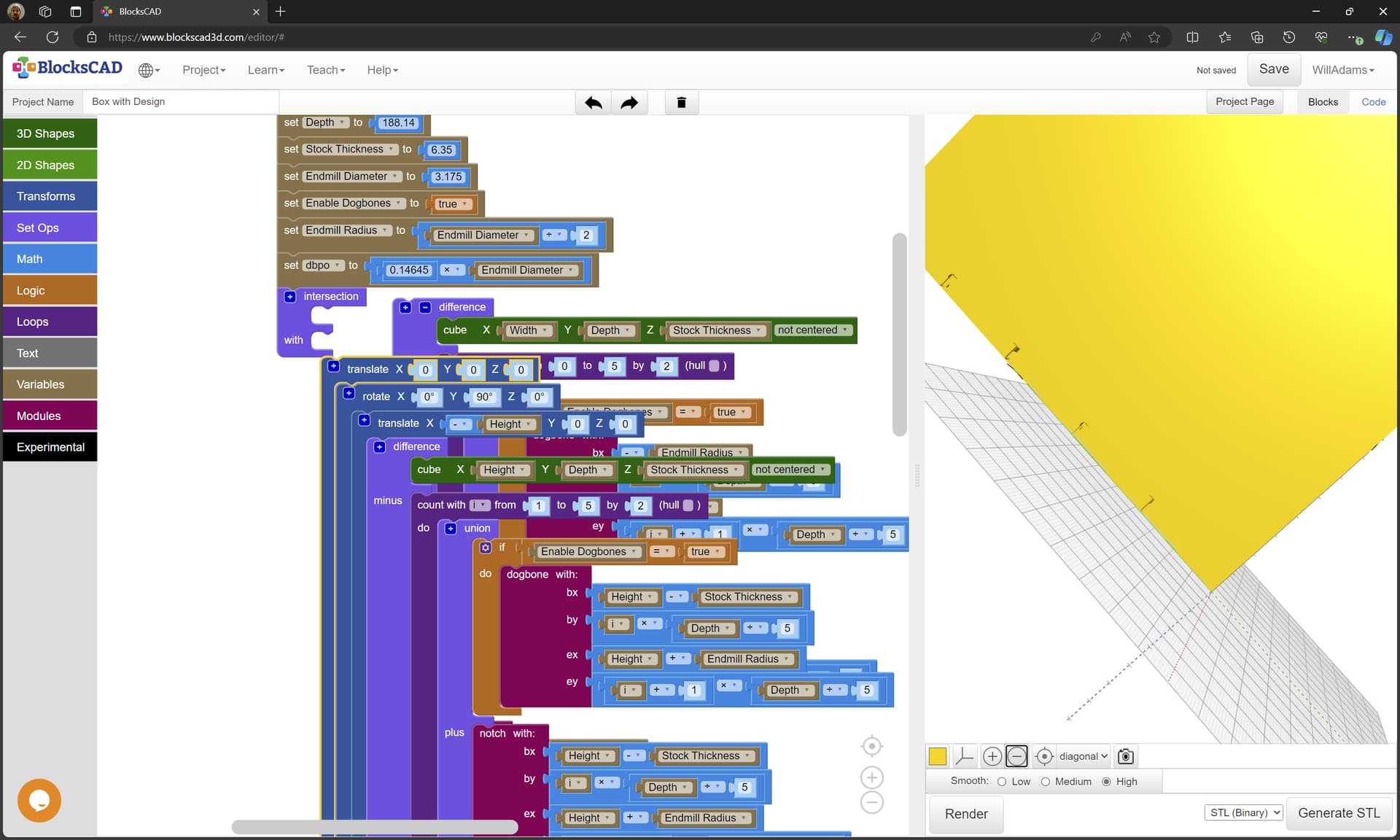
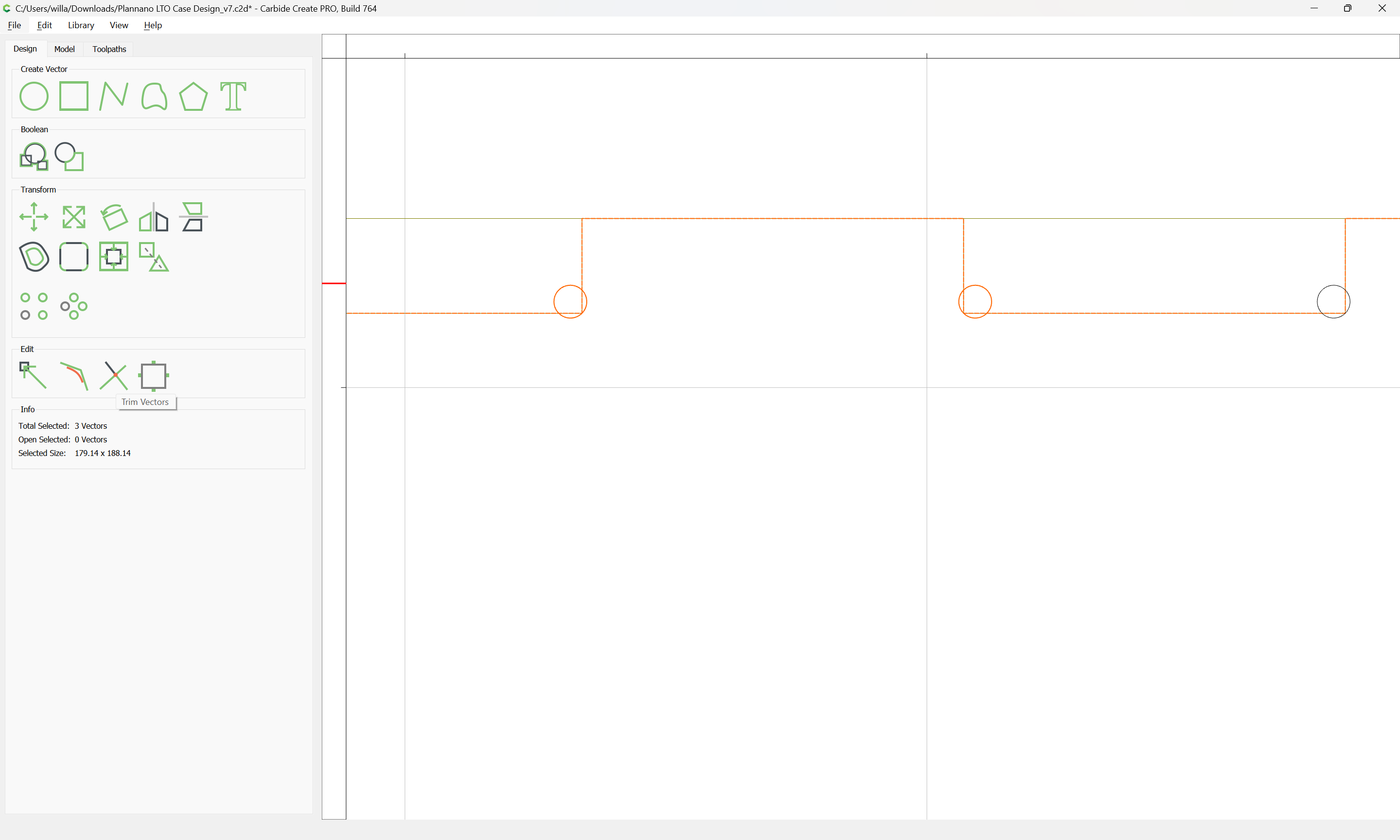
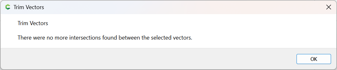
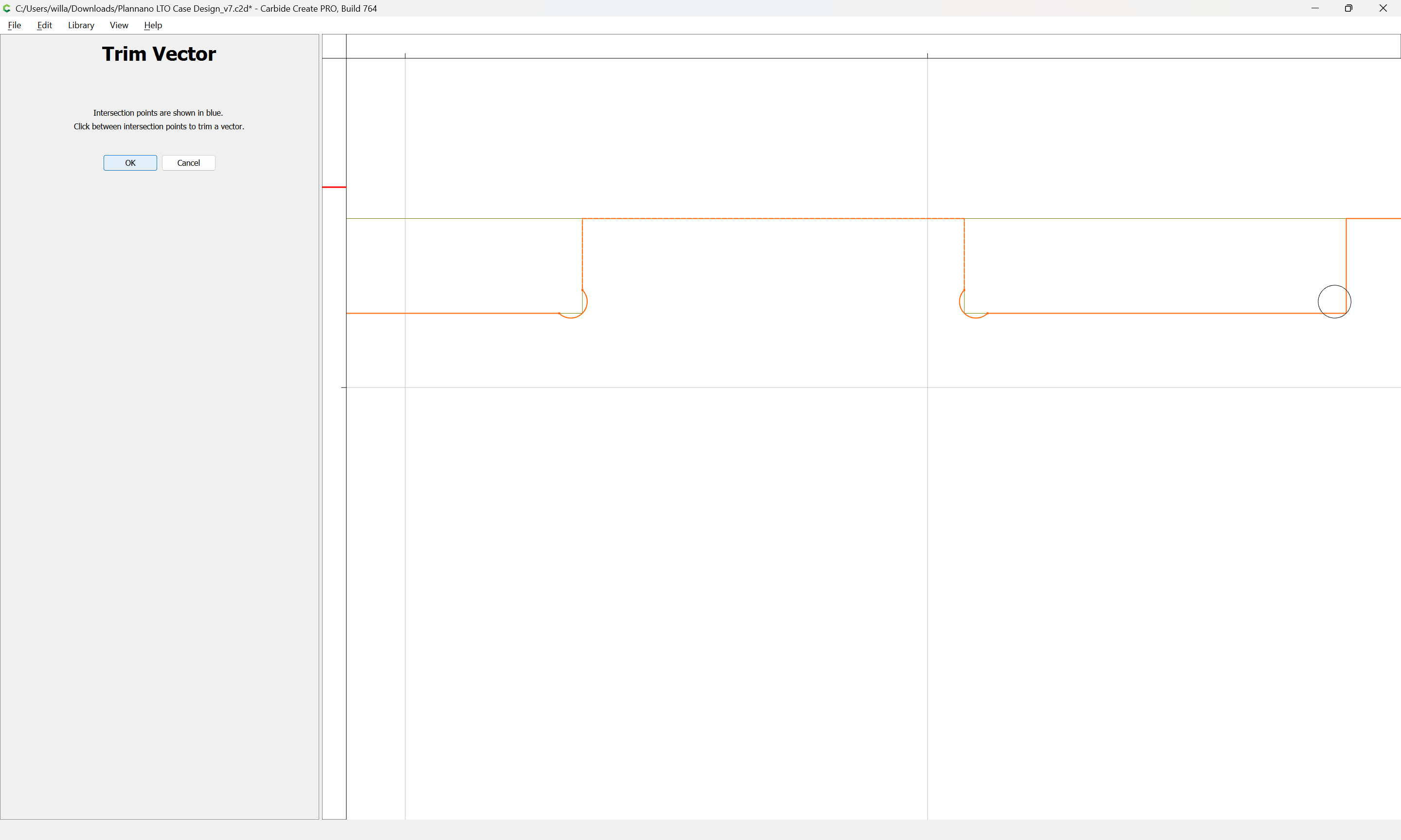
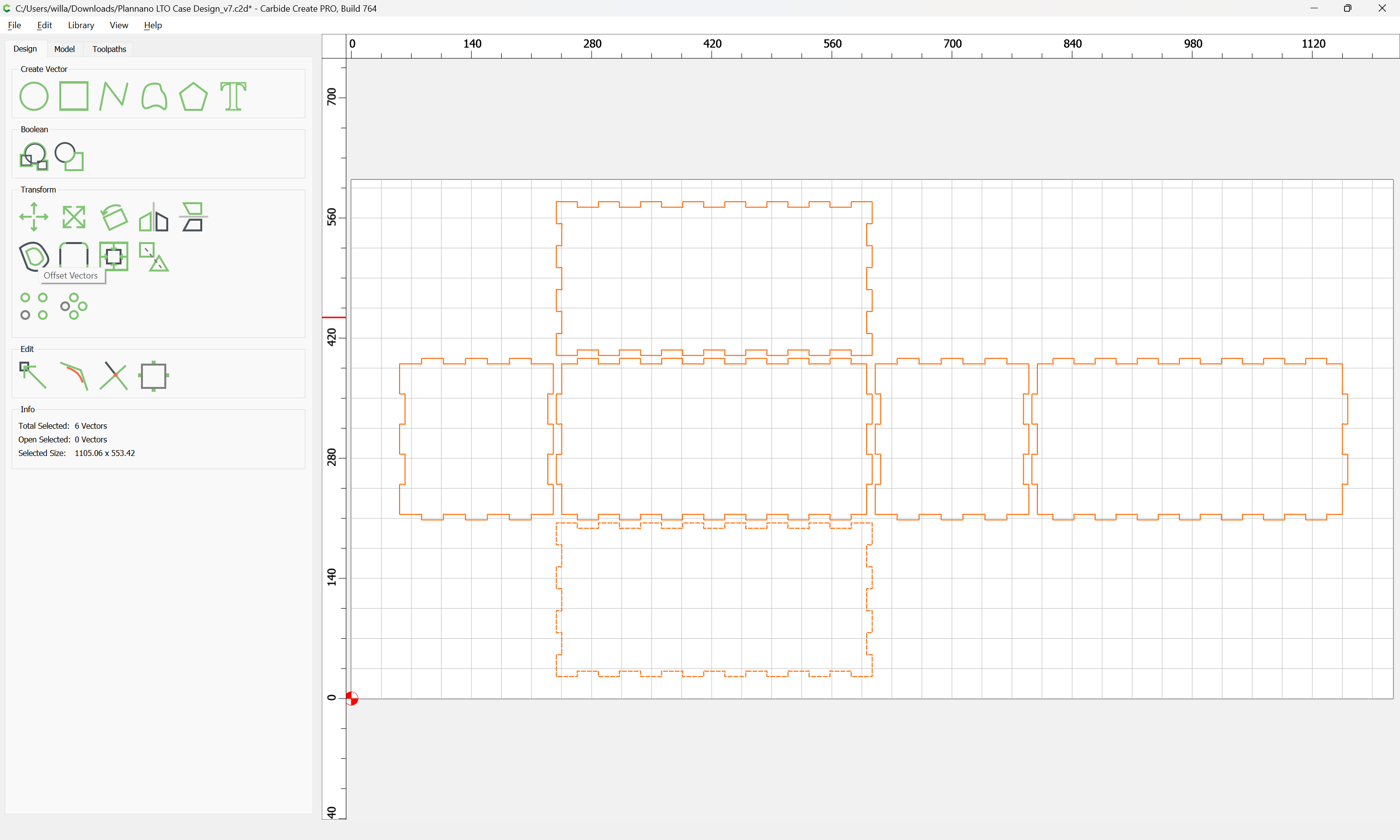
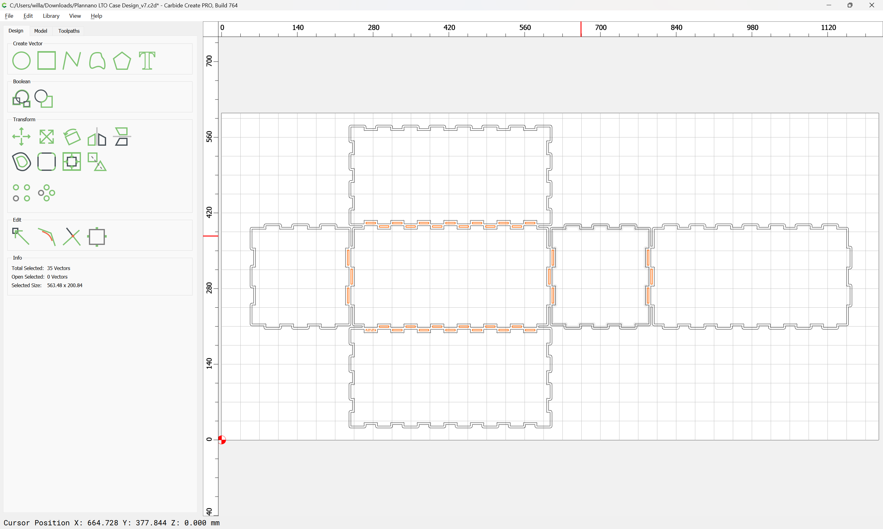
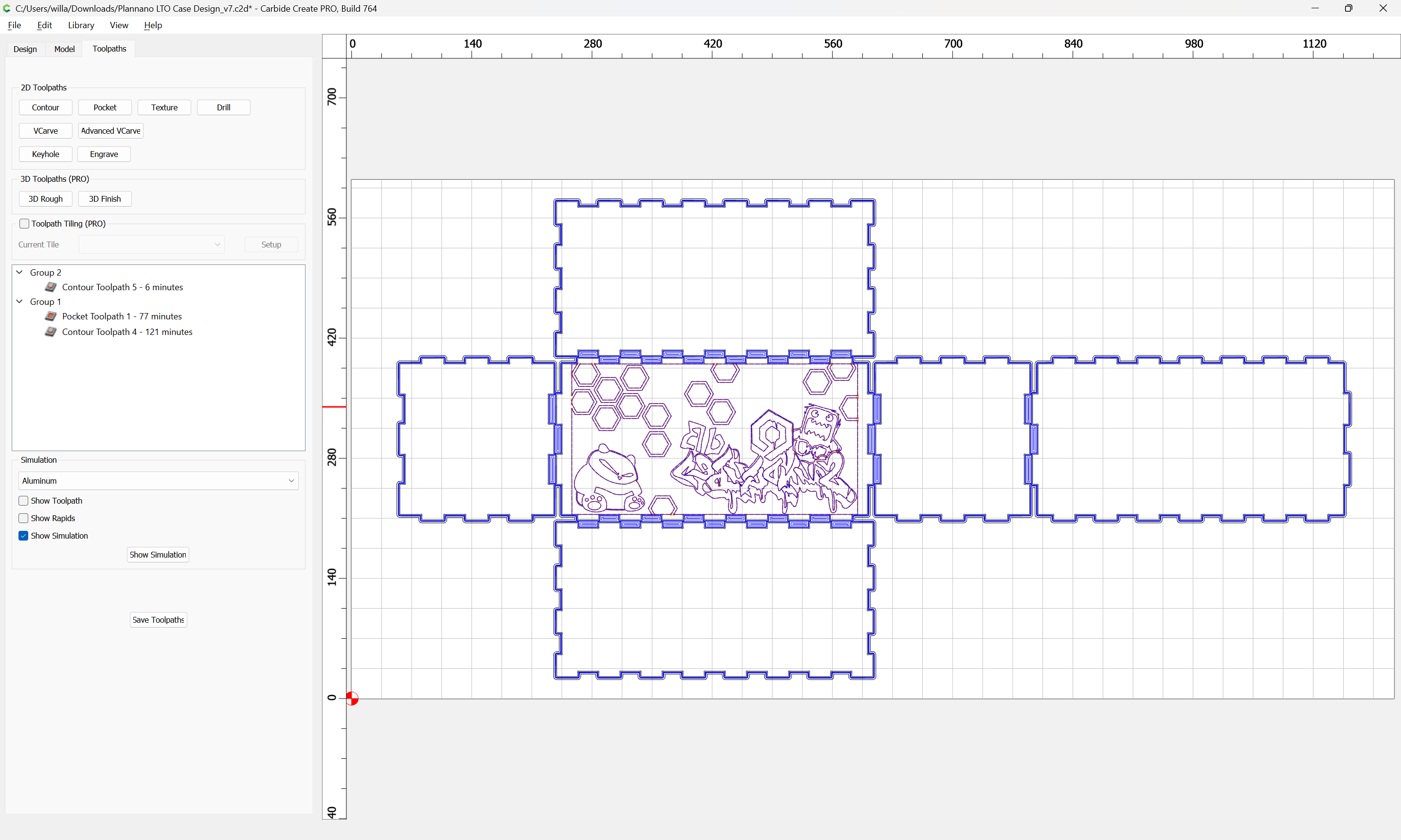
We then select the two squares and make as many duplicates as are needed to create 8 notches for the box bottom, and 7 notches for the box front using the Linear Array tool:
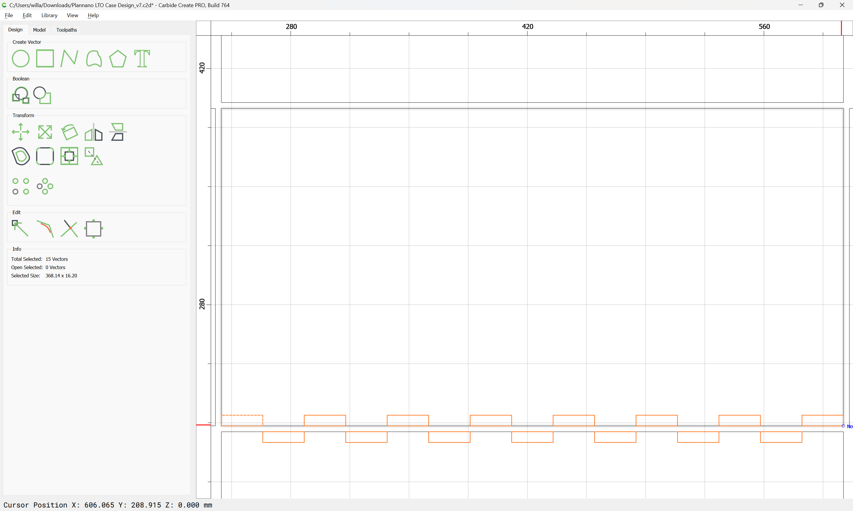
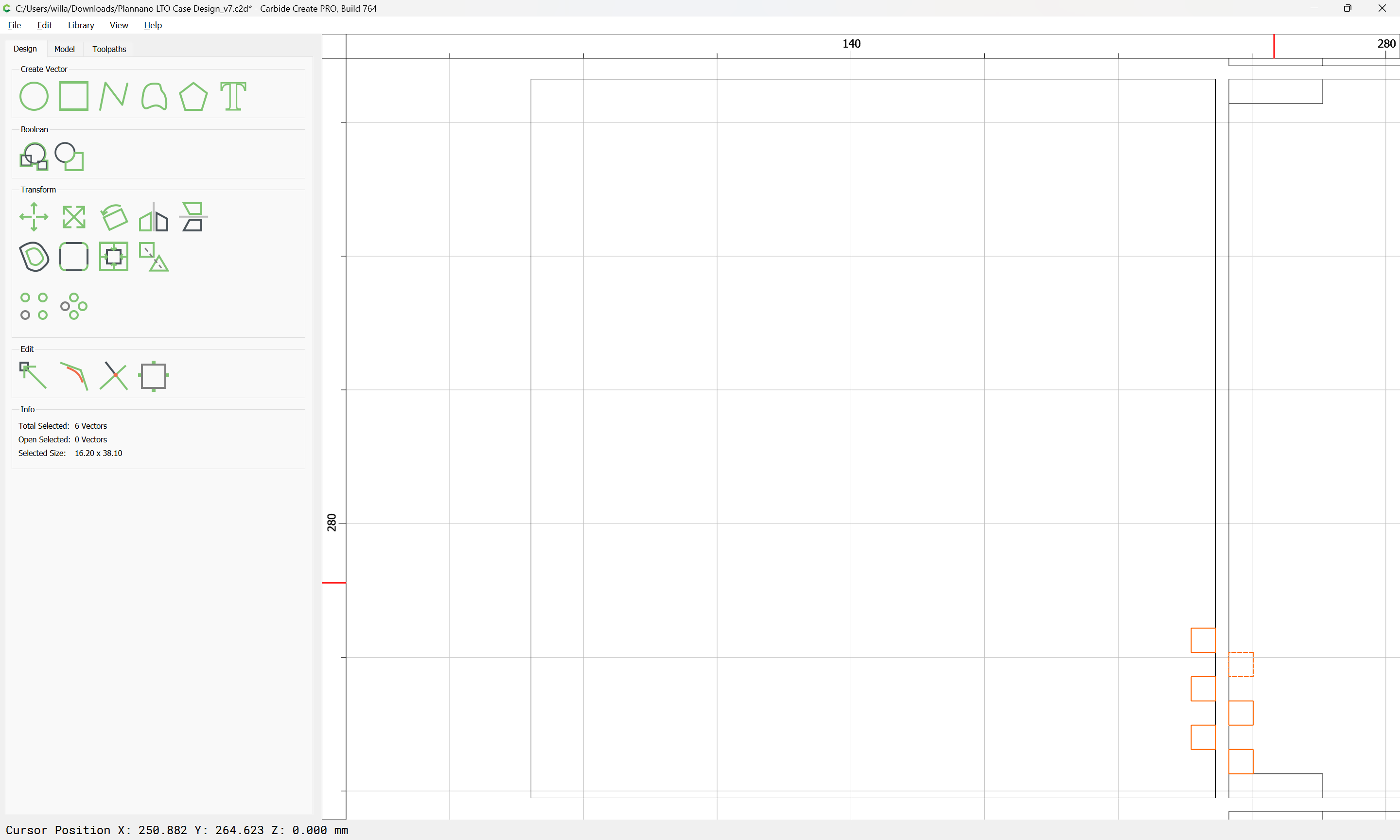
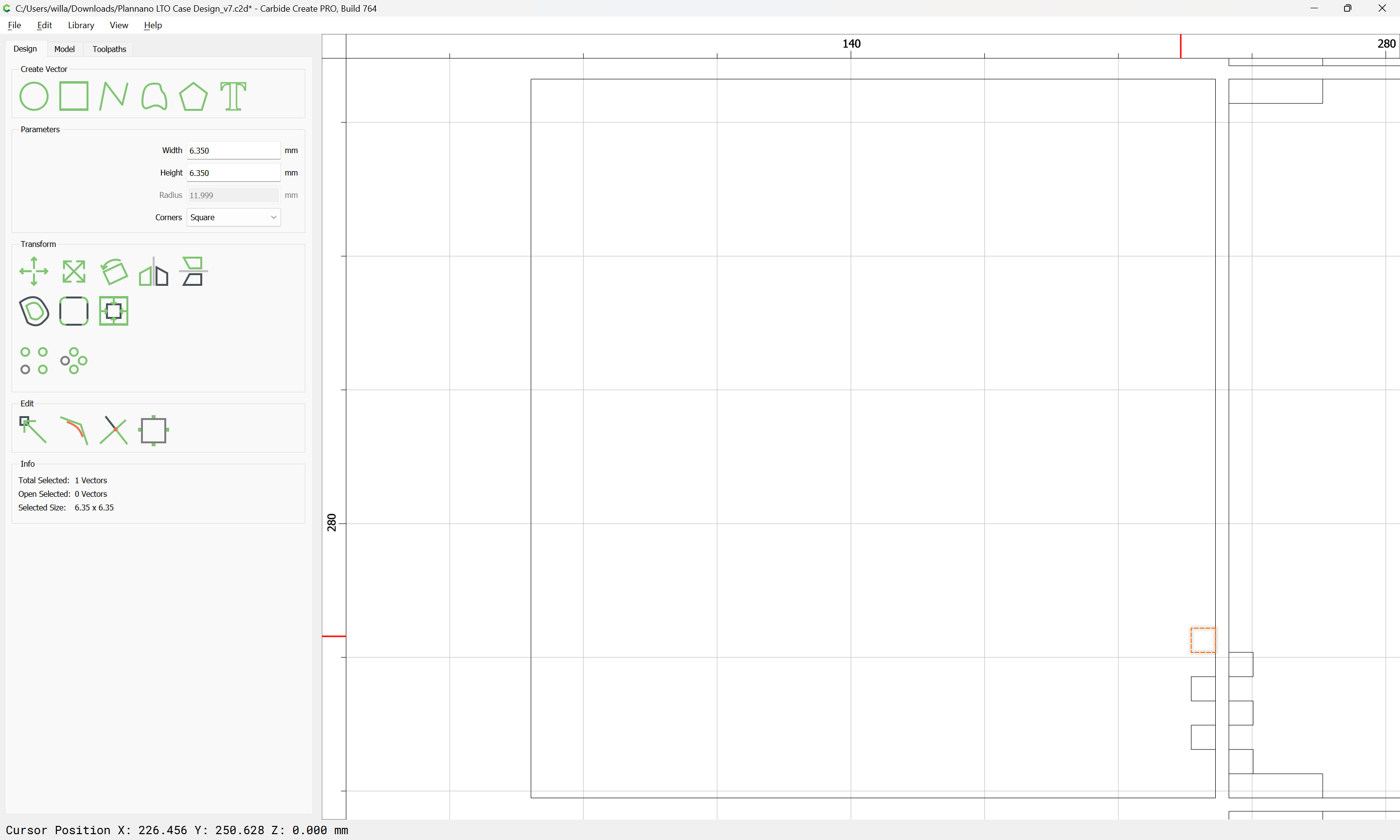
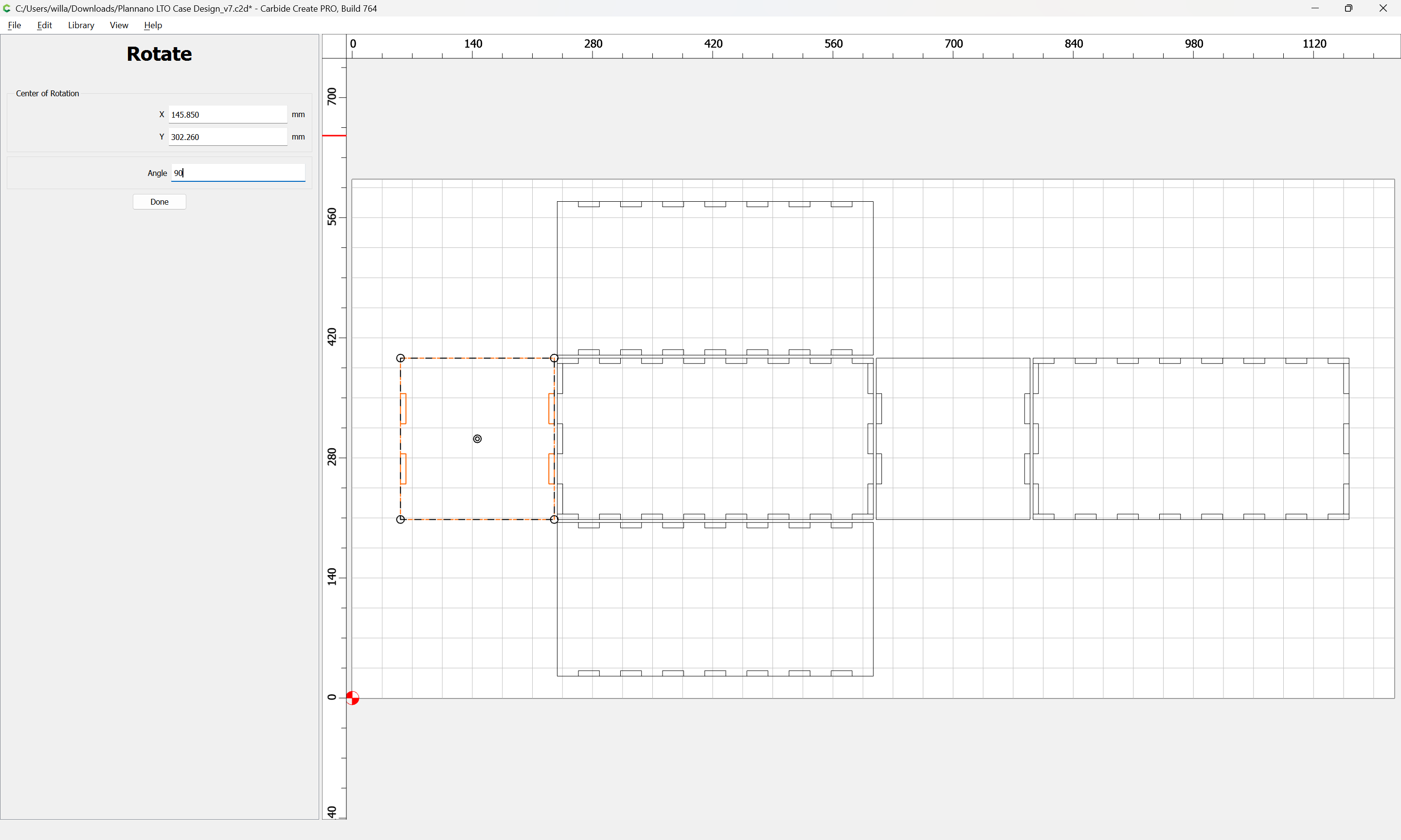
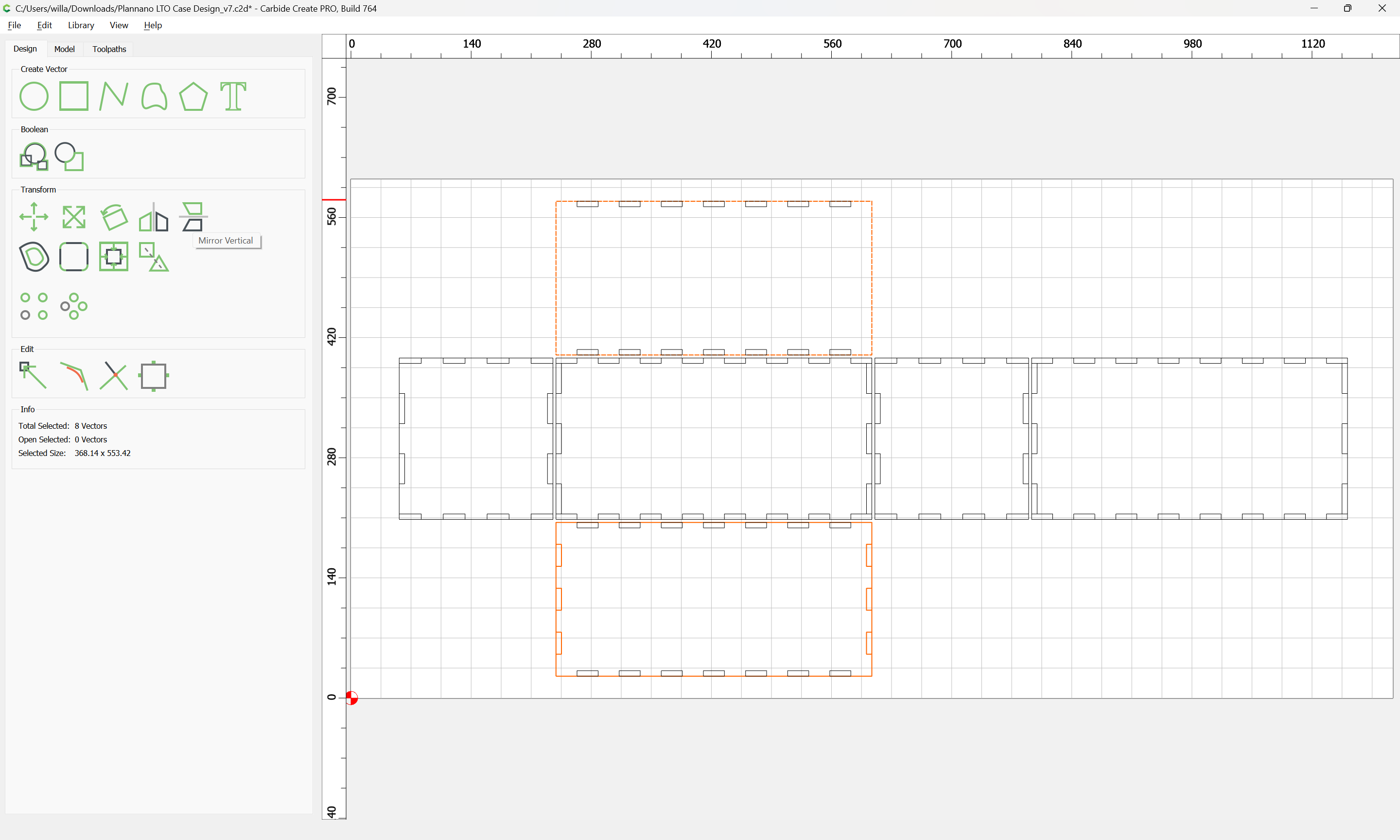
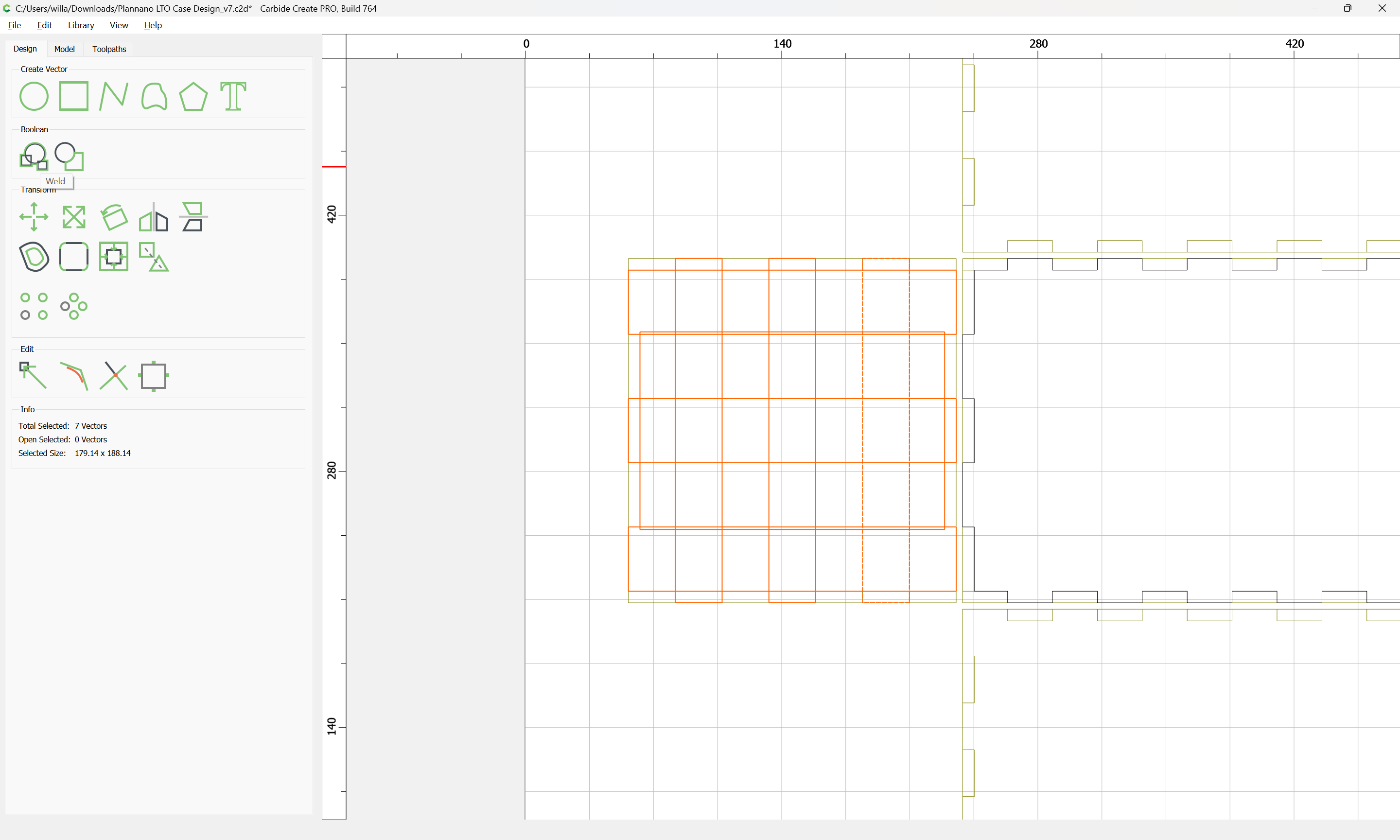
Repeat this for the other edges. Note that for the side it will be necessary to inset by the stock thickness, so duplicating this and dragging it into alignment will help in getting things lined up as desired:
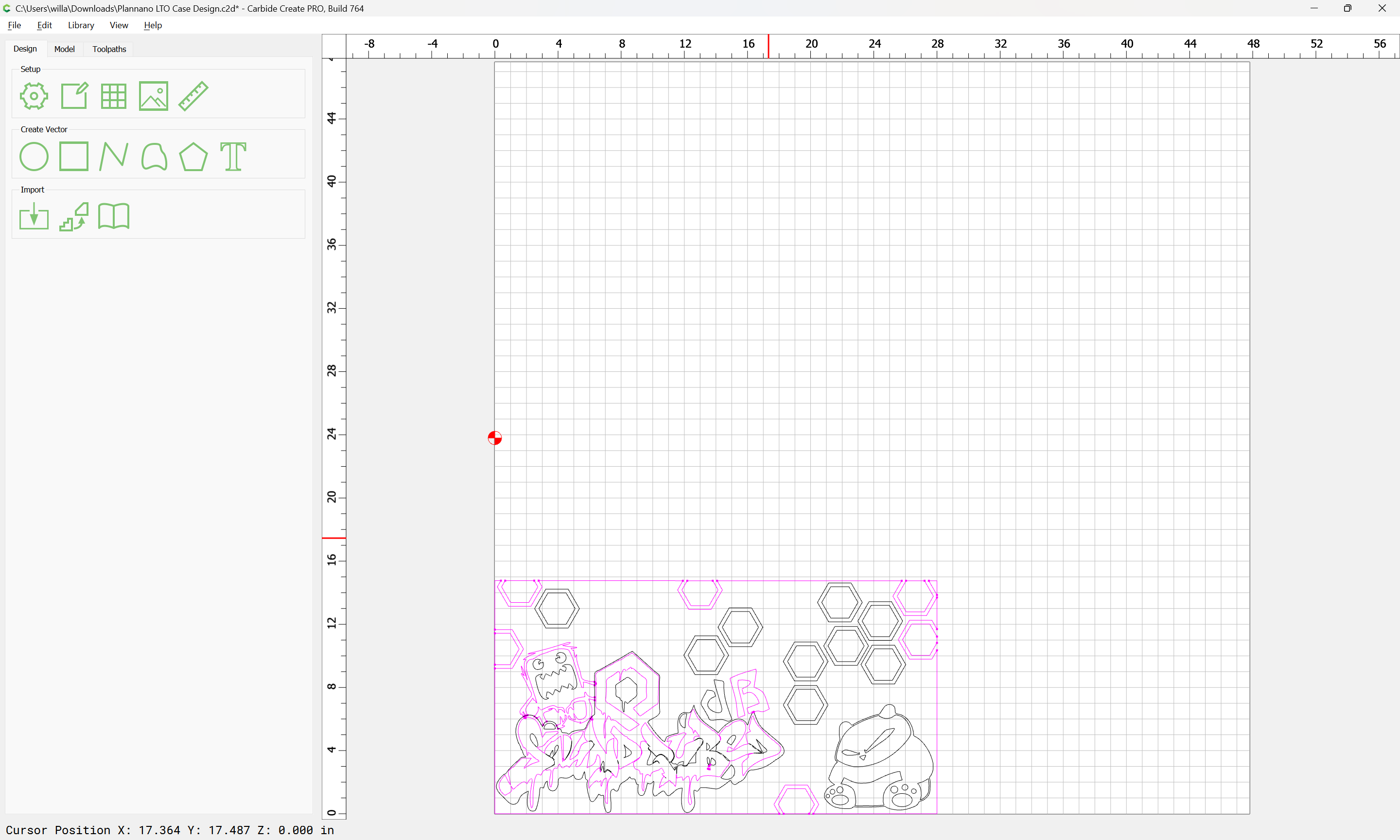
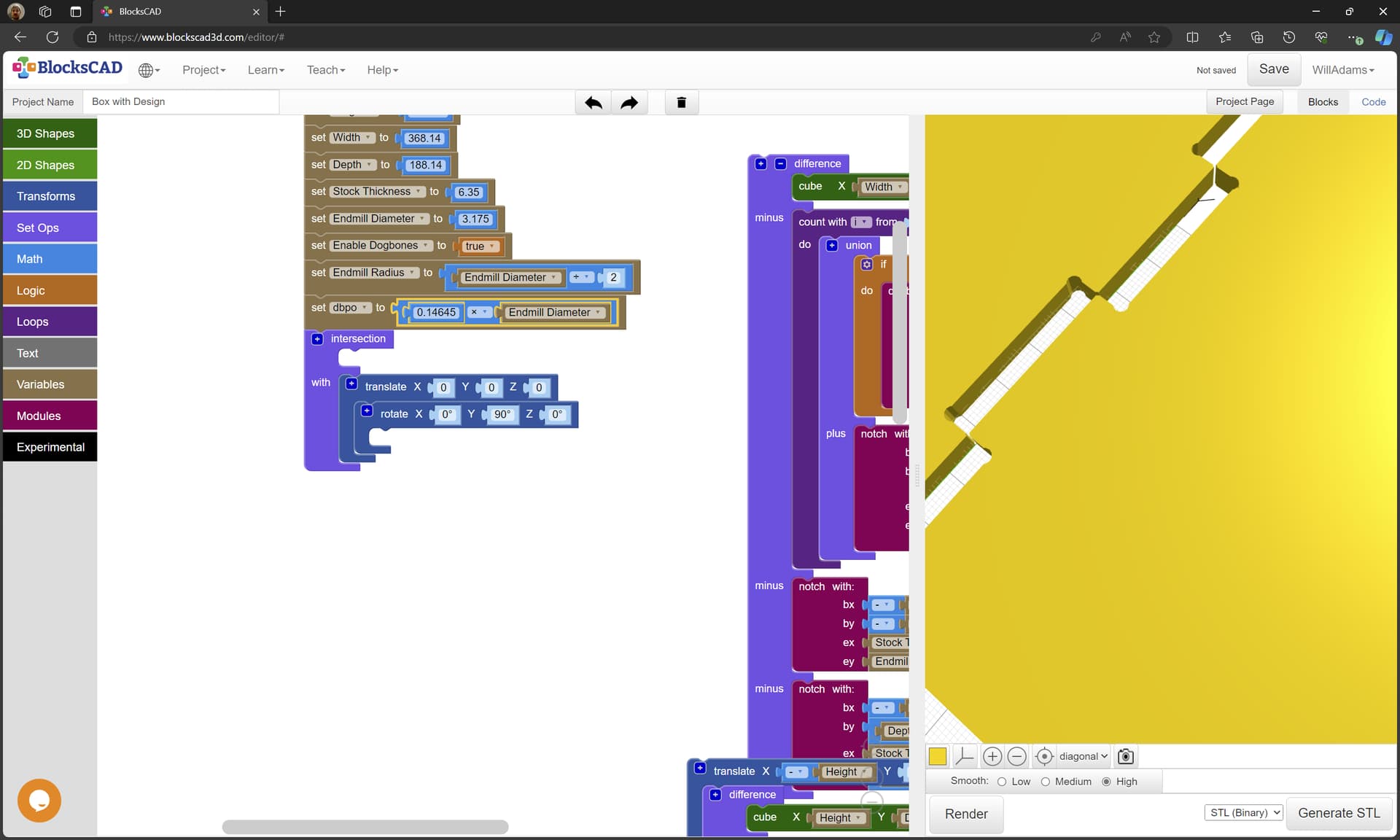
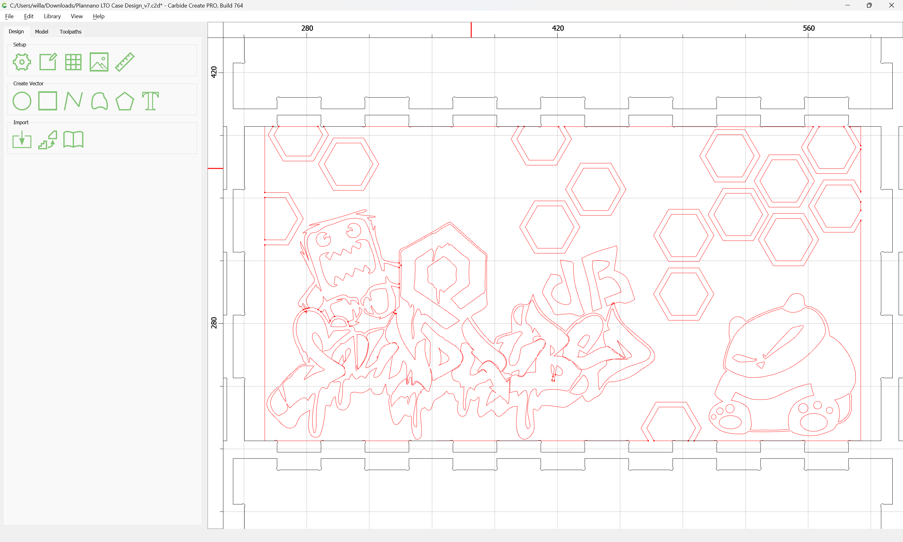
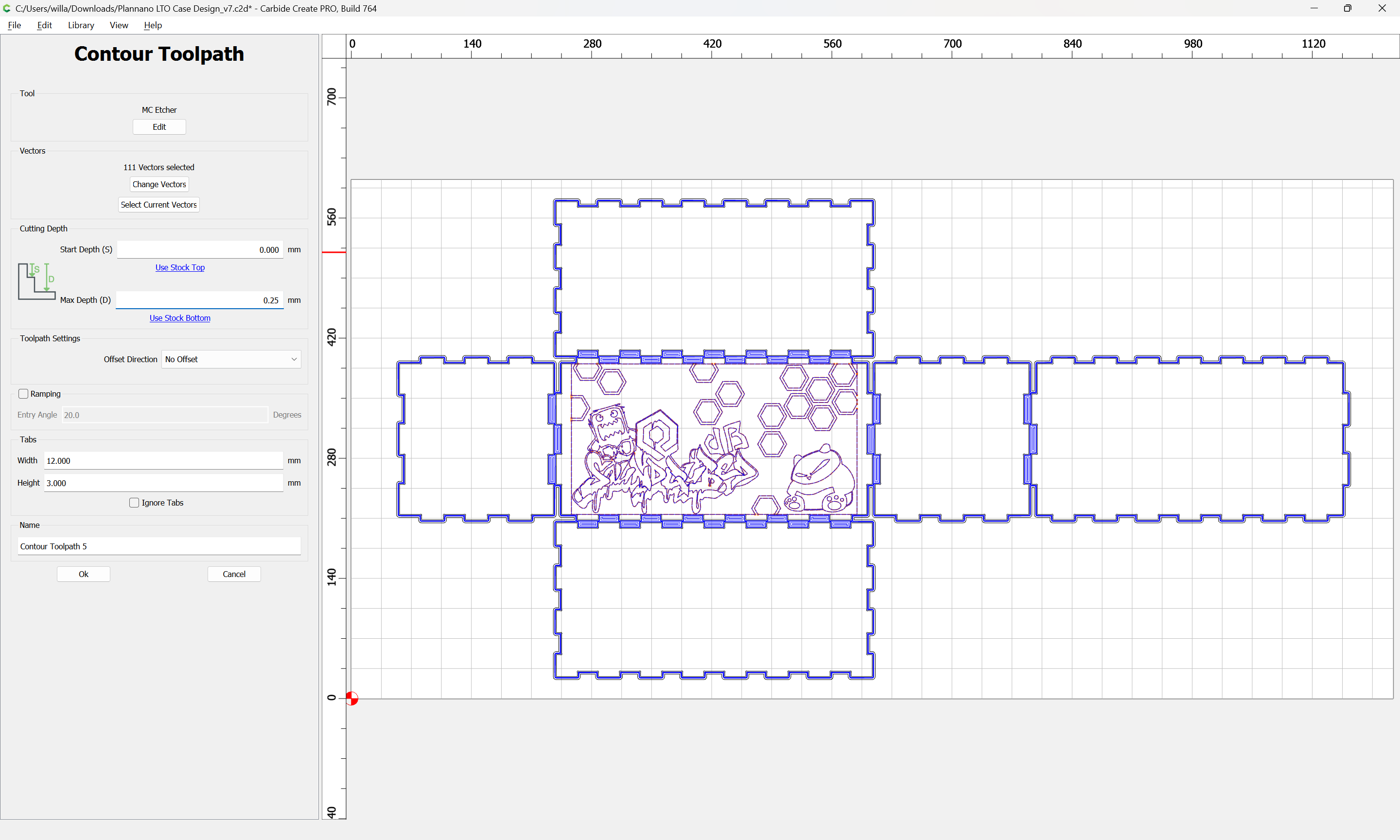
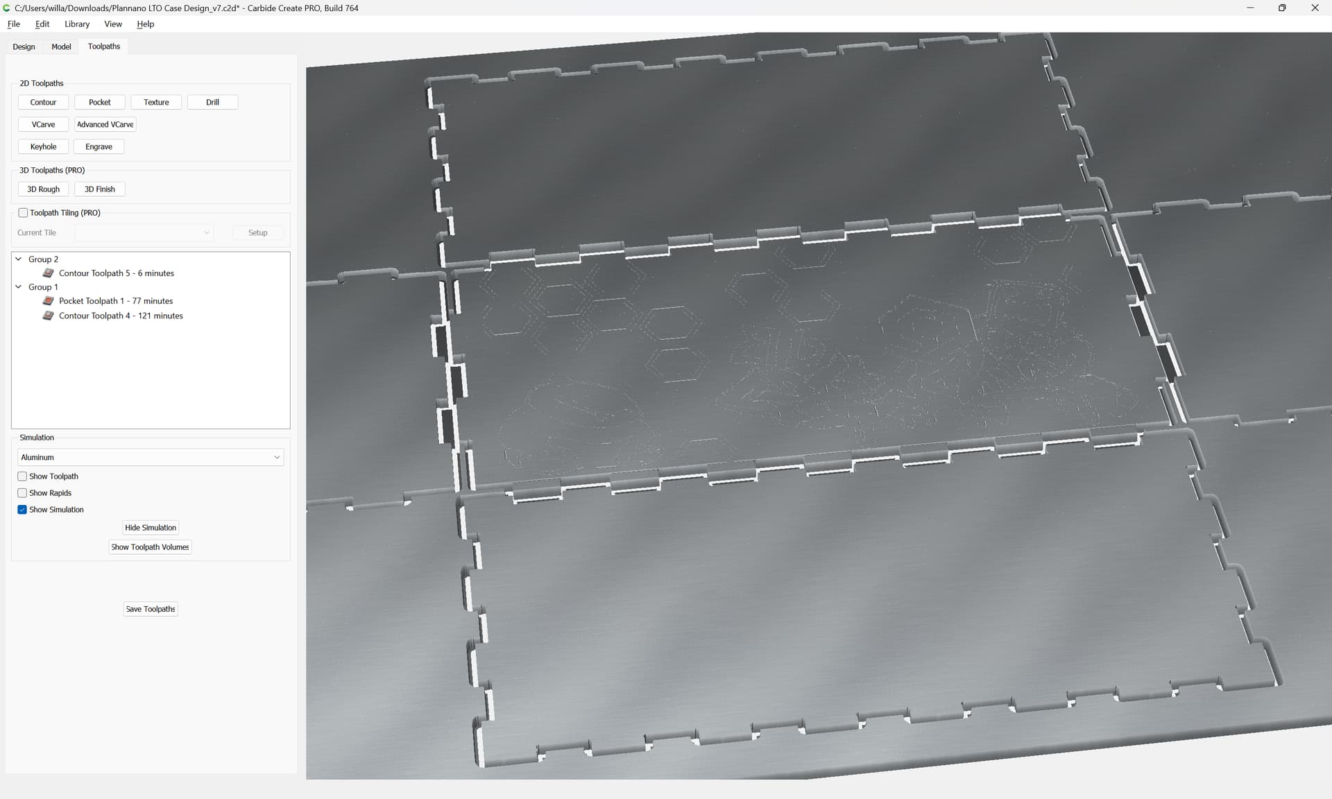
The vital part I forgot was that, the etching would need to be reversed, as once it is assembled, the artwork would on the interior. If that makes sense? This will all be cut from clear polycarbonate.
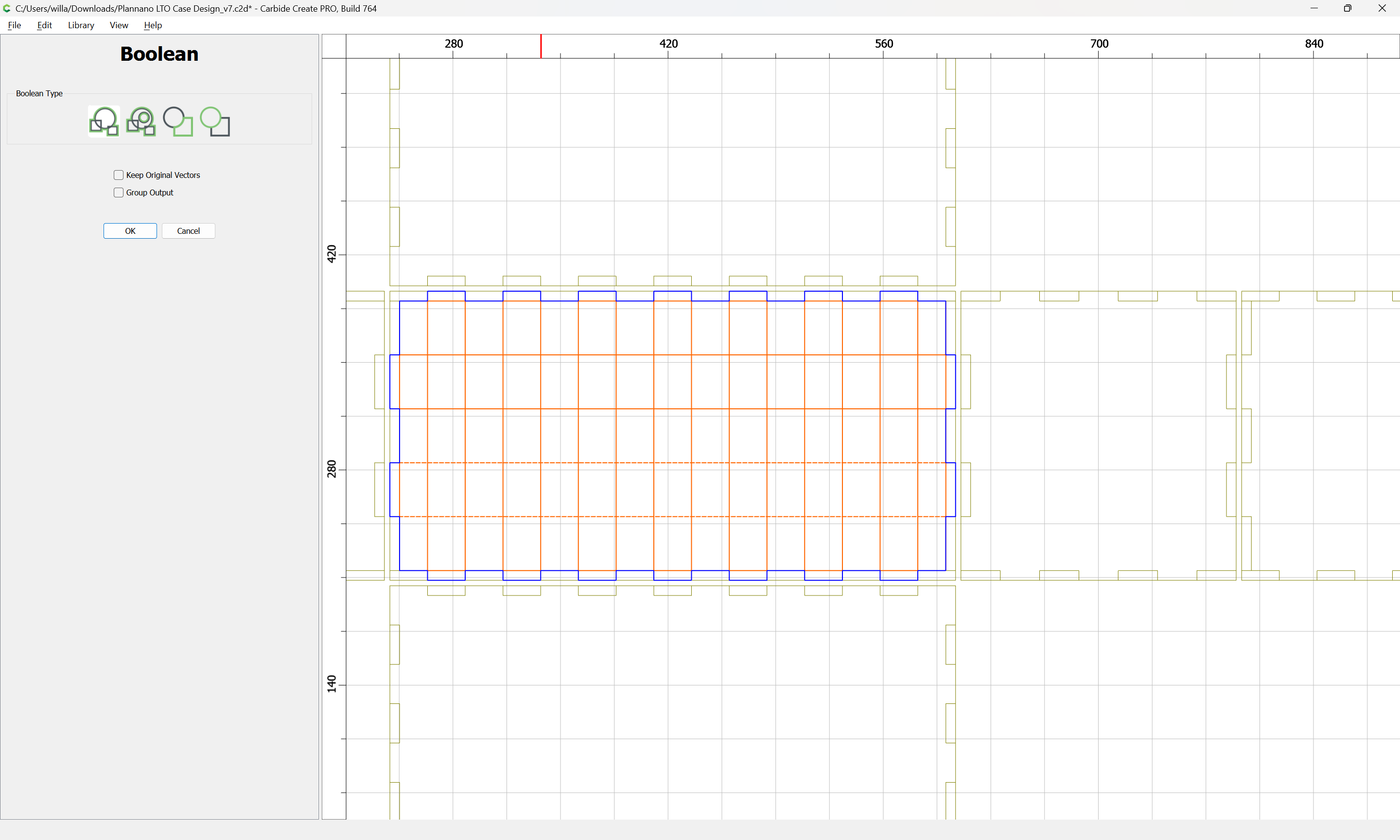
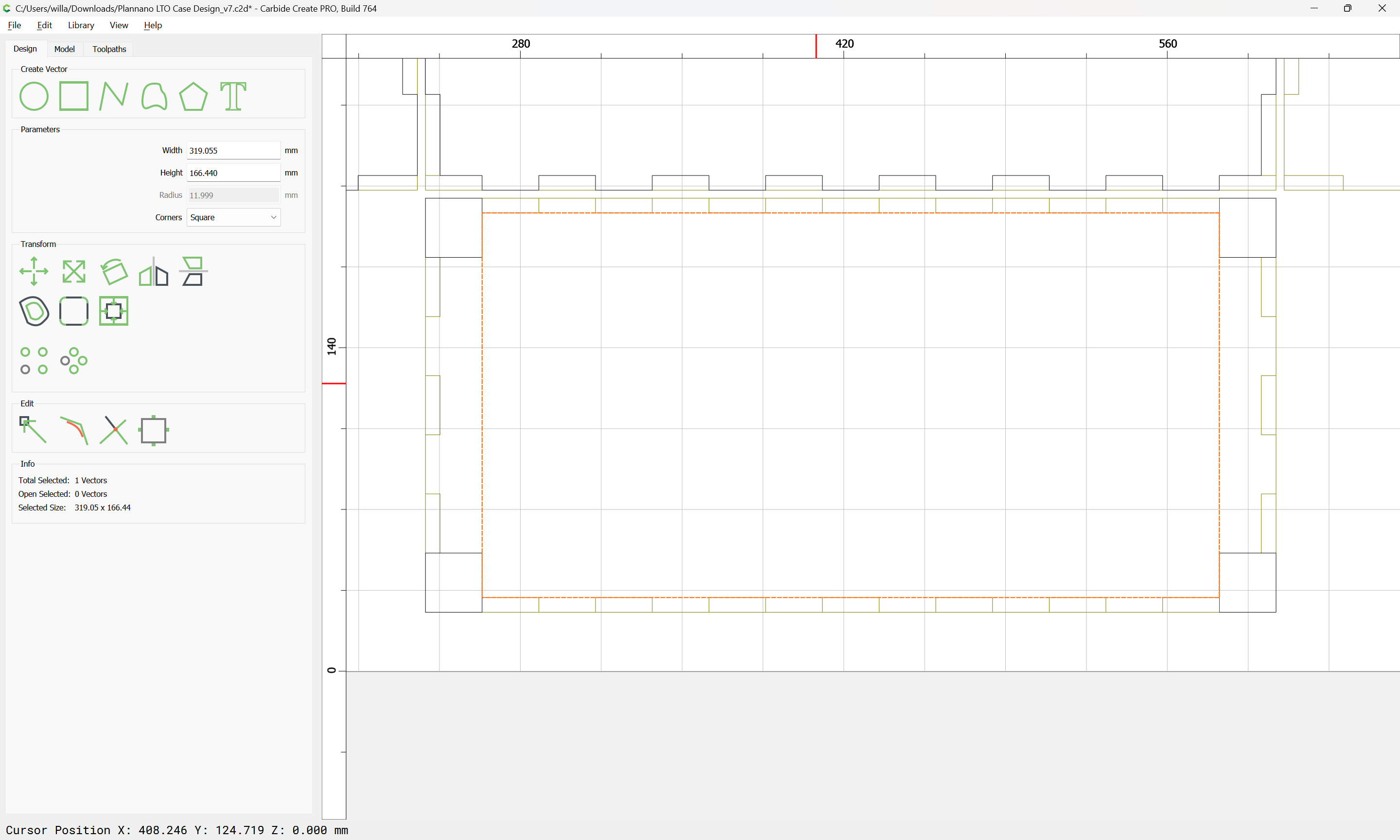
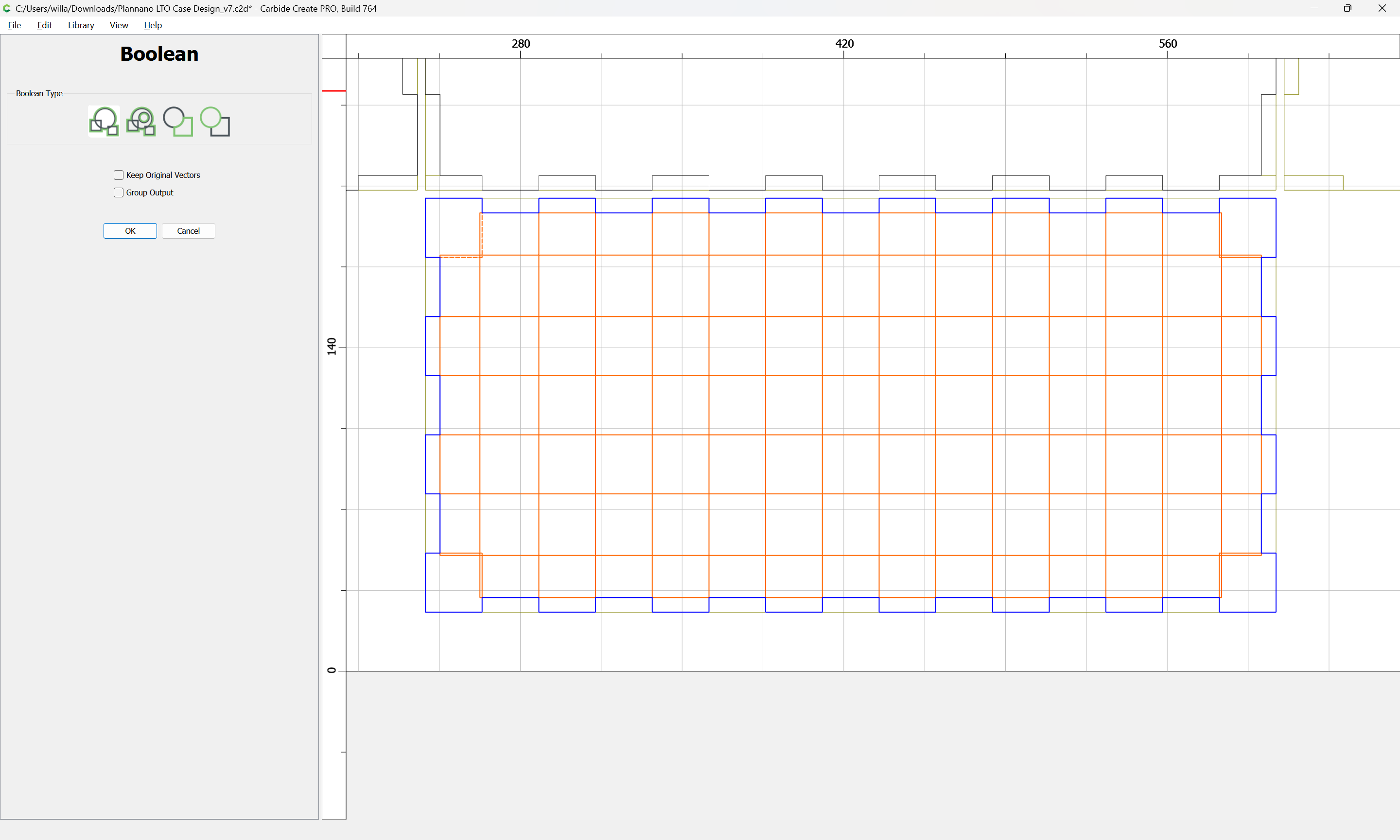
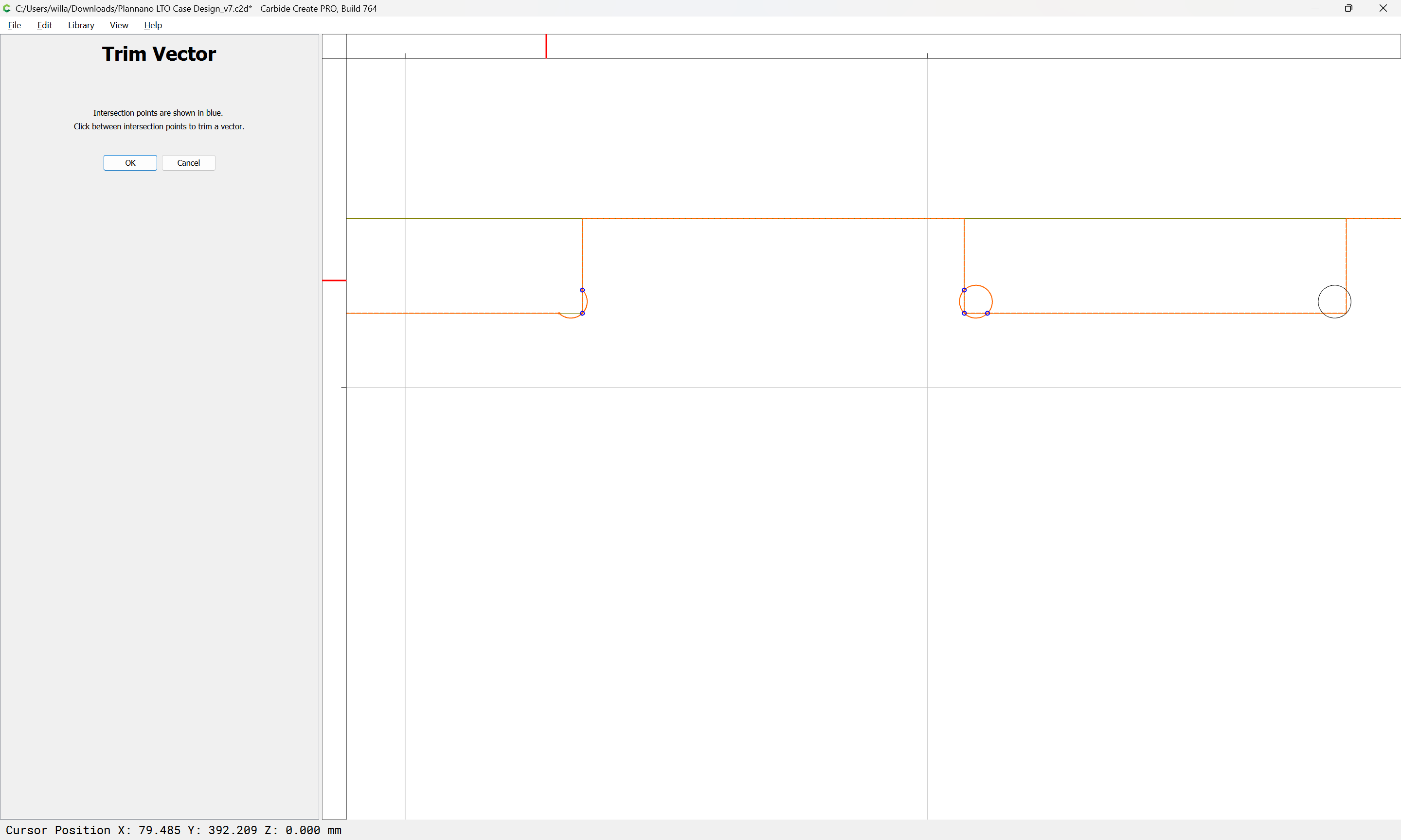
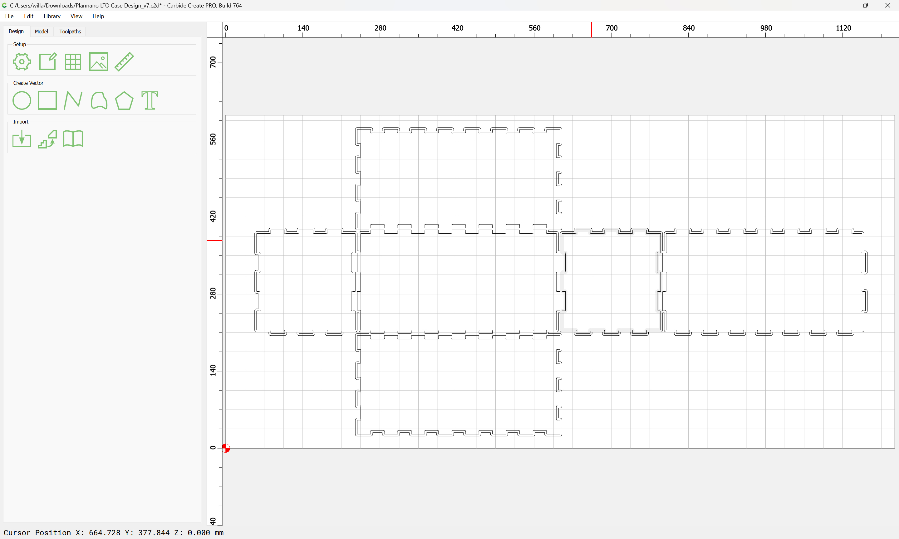
The problem is the geometry depicts what we want to remove, not what we want to keep.
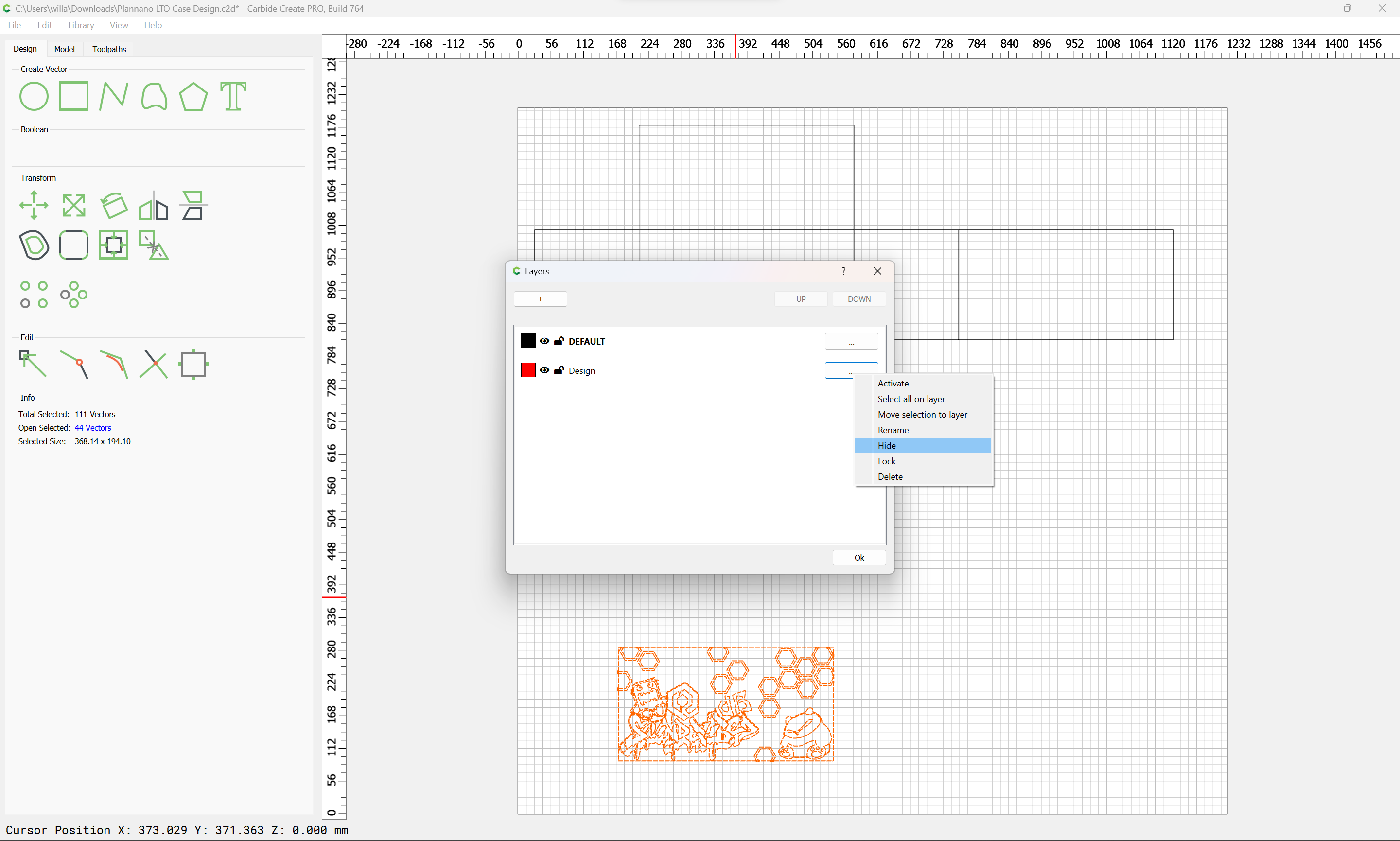
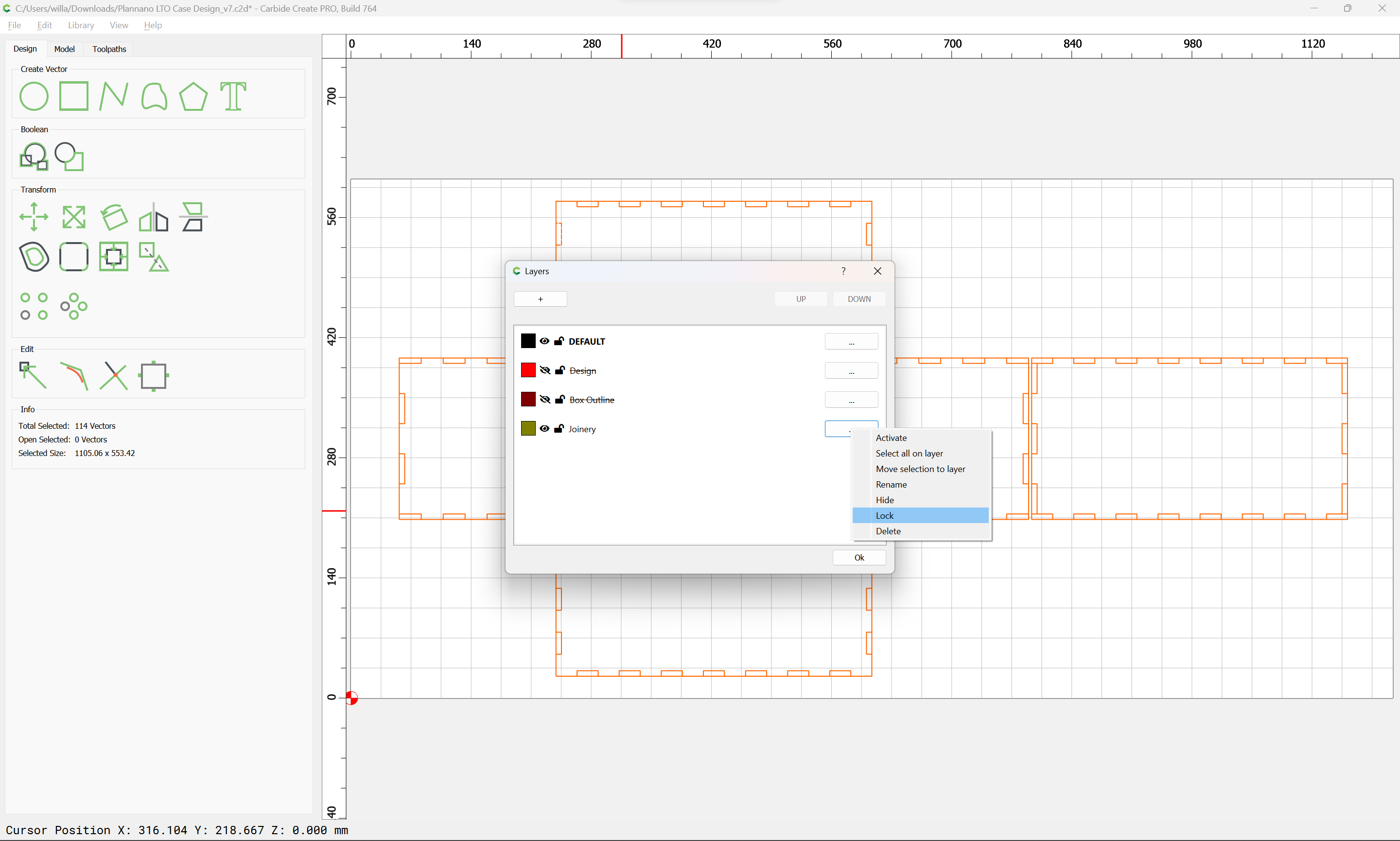
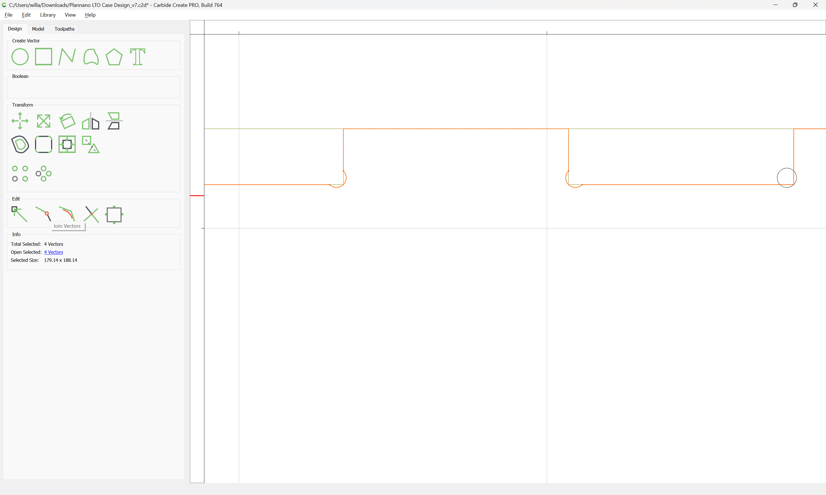
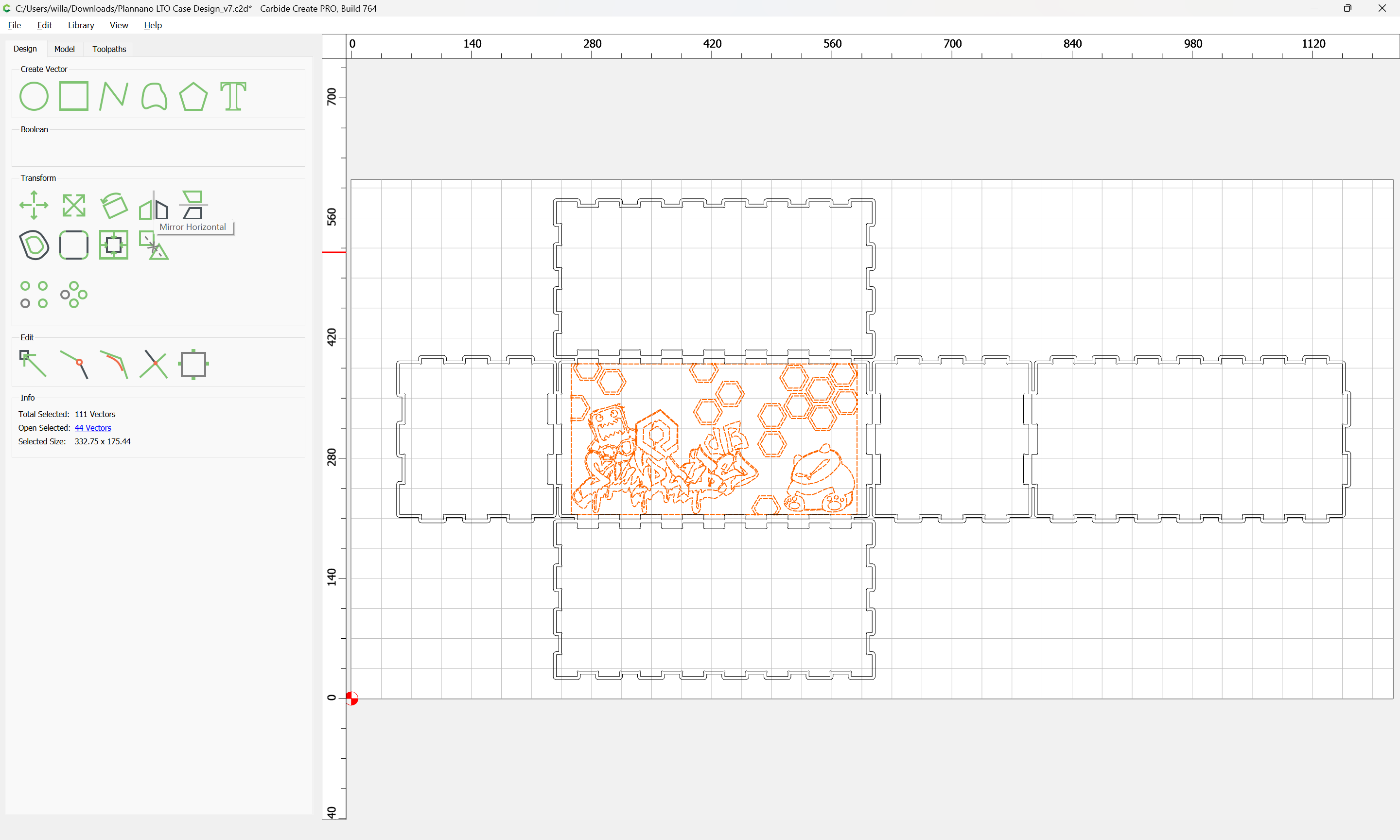
Since Carbide Create doesn’t have a concept of a Composite Path with multiple pieces of geometry treated as a single element, it is much easier if one unions the design rather than attempts multiple subtractions.
There are a couple of ways to arrive at geometry which could be unioned — the easiest way is to just put everything on a separate layer and lock it: