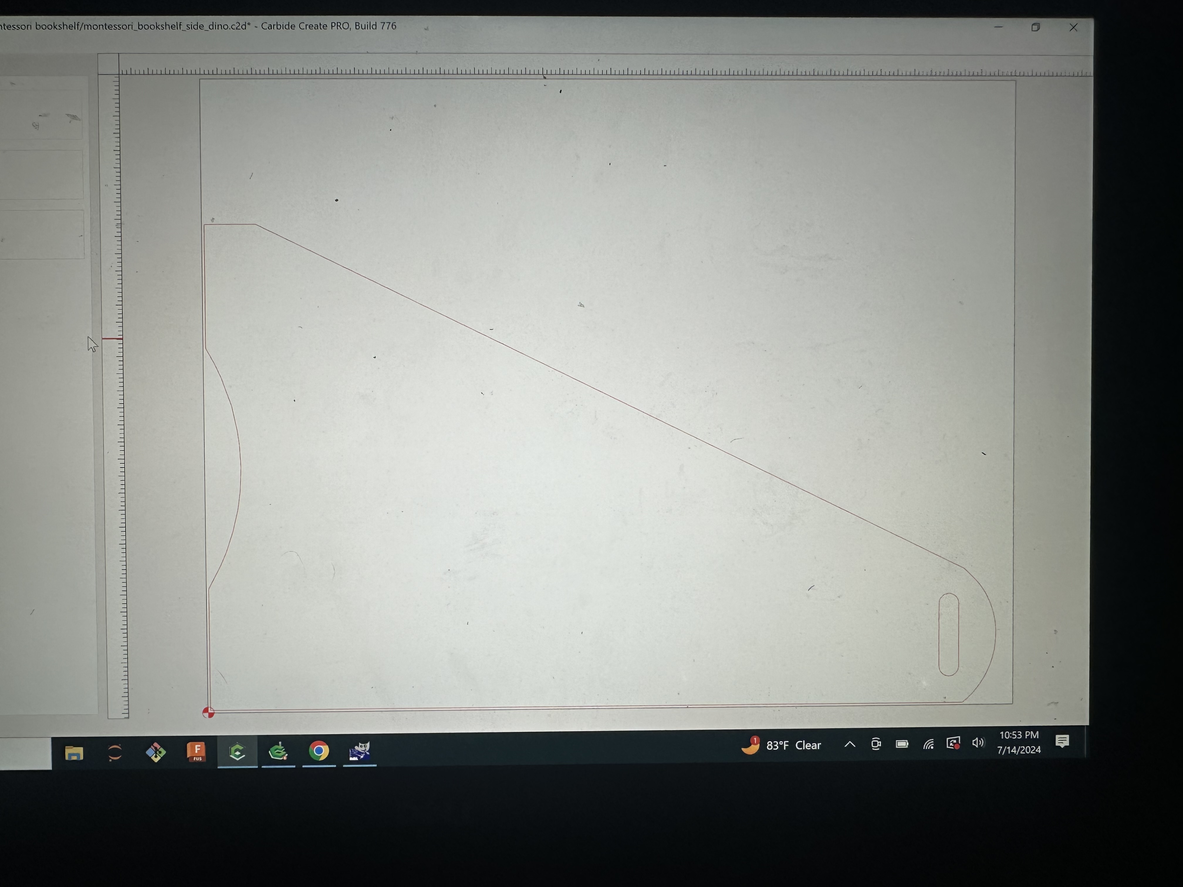
I have triangular sides for a Montessori bookshelf that I’ve designed. I duplicated the shape and mirrored it to make the other side. Reason for the mirror is to make designs on the outsides.
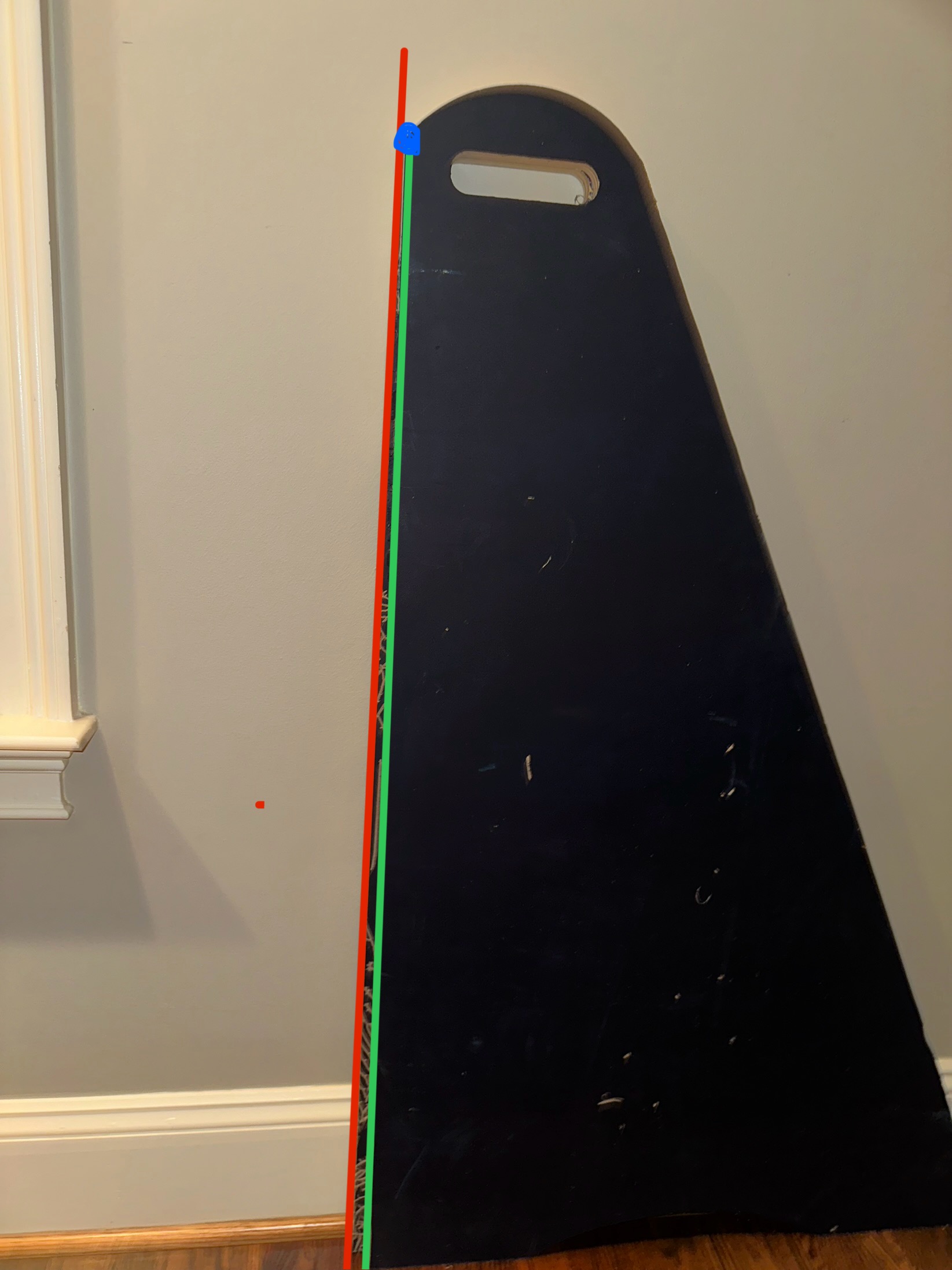
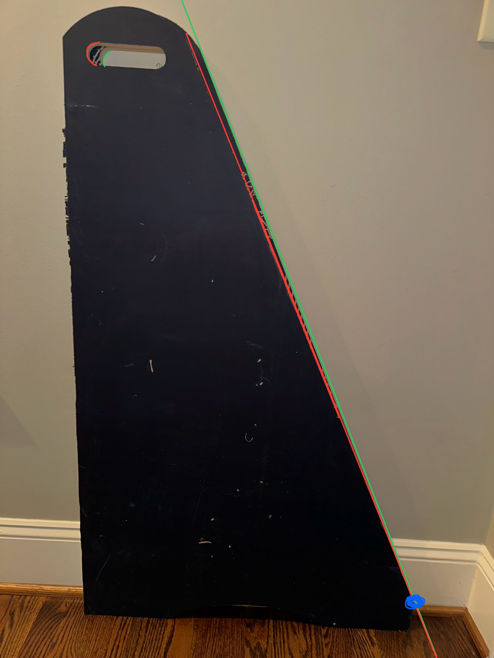
Twice now, the mirrors don’t complement each other! I’ve made sure that everything is the same - flipped the mirrors back to make sure they align to the original shape and both times they failed. These are not handed/chiral shapes, so I’m left confused and thinking this is either a problem I’m not seeing…
Could this be a software thing? Calibration? Etc? Pretty frustrated, especially since the cost of plywood is nuts…
Additional info:
2 diff .c2d files were used with the same specs
Stock Size = same
Thickness = same
Zeros = same (0.75”)
Machine = Shapeoko 5 Pro 4x4
Cut = contour cut ON the line with a 1/8” endmill to 0.745”
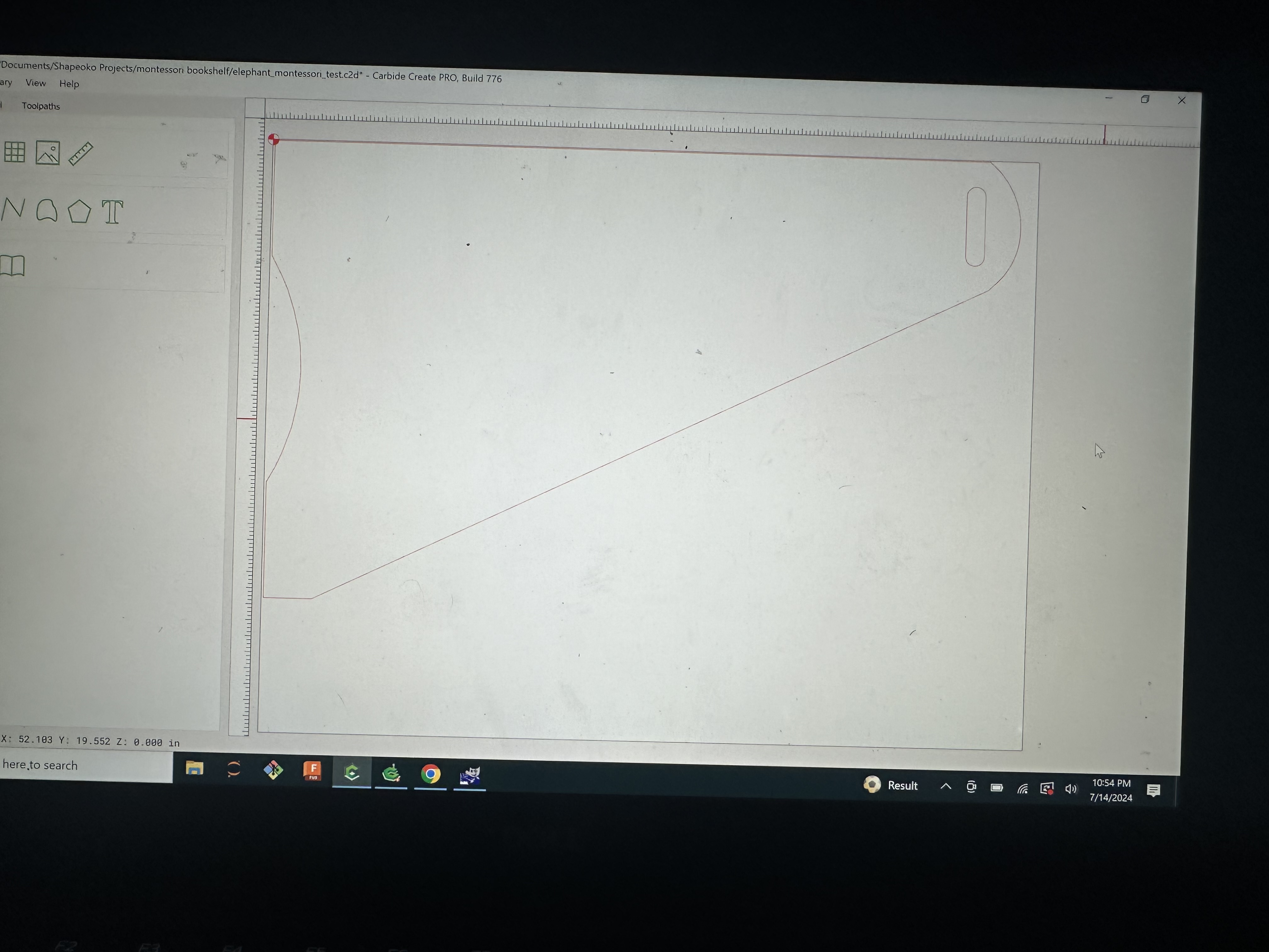
Pics of the shape cuts are below. I used contour cuts with a 1/8” end mill to cut out the shapes. You can see them below. The ONLY thing different is where on the stock the machine is cutting them and the tool path zero (bottom left - cut1) / (top left - cut 2)
Again - these are EXACT mirror images of each using a duplicate of the original shape. One would expect that they would cut out the same.
I now have 4 cut sides in total. (2x side #1 and 2x side #2). Both the sides #1 align just fine with each other, as do both #2 sides, but #1 does not align with #2?
Thx for the response, @WillAdams , but I don’t think those are the issue I’m facing. I put some additional context in the description if you care to check it again.
Have you checked that the machine is cutting perfectly square?
Probably the easiest way to check is to program a square or a rectangle to cut out, then measure the diagonals. The larger the better, but you need to be able to measure the diagonals accurately - a tape measure probably isn’t precise enough.
If the diagonals don’t match, then all your cuts are skewed, and that could explain what you are seeing.
@mhotchin - I thought of this, too and only used my tape measure. That being said, this is the literature on squaring for the S5pro: Troubleshooting Homing
Although- thinking through this again, 25mm is definitely well in line with the zeroing tolerance built into the s5p, so squaring may in fact be the issue.
My first instinct is that it’s a squaring issue. Most likely you will need to make minor adjustments to one of the homing switches on the Y-axis, bringing it forward or backwards, so that it triggers sooner or later. That will bring gantry much closer to true square when the machine is initialized. You will need to do some testing and measurement to figure out which direction to adjust things.
Michael’s test is valid. Another crude way you could gauge the squareness of your gantry would be to rest one edge of a large, decent-quality T or framing square against one of the Y rails, center the spindle to the perpendicular edge, and jog along it’s length. You’re looking for any deviation of the spindle away from the reference to indicate which side of the gantry needs to come forward.
One thing I have done when testing an intricate design is use MDF. I go to the RE Store and pick up (desks, bookshelves, whatever) all made with cheap MDF.
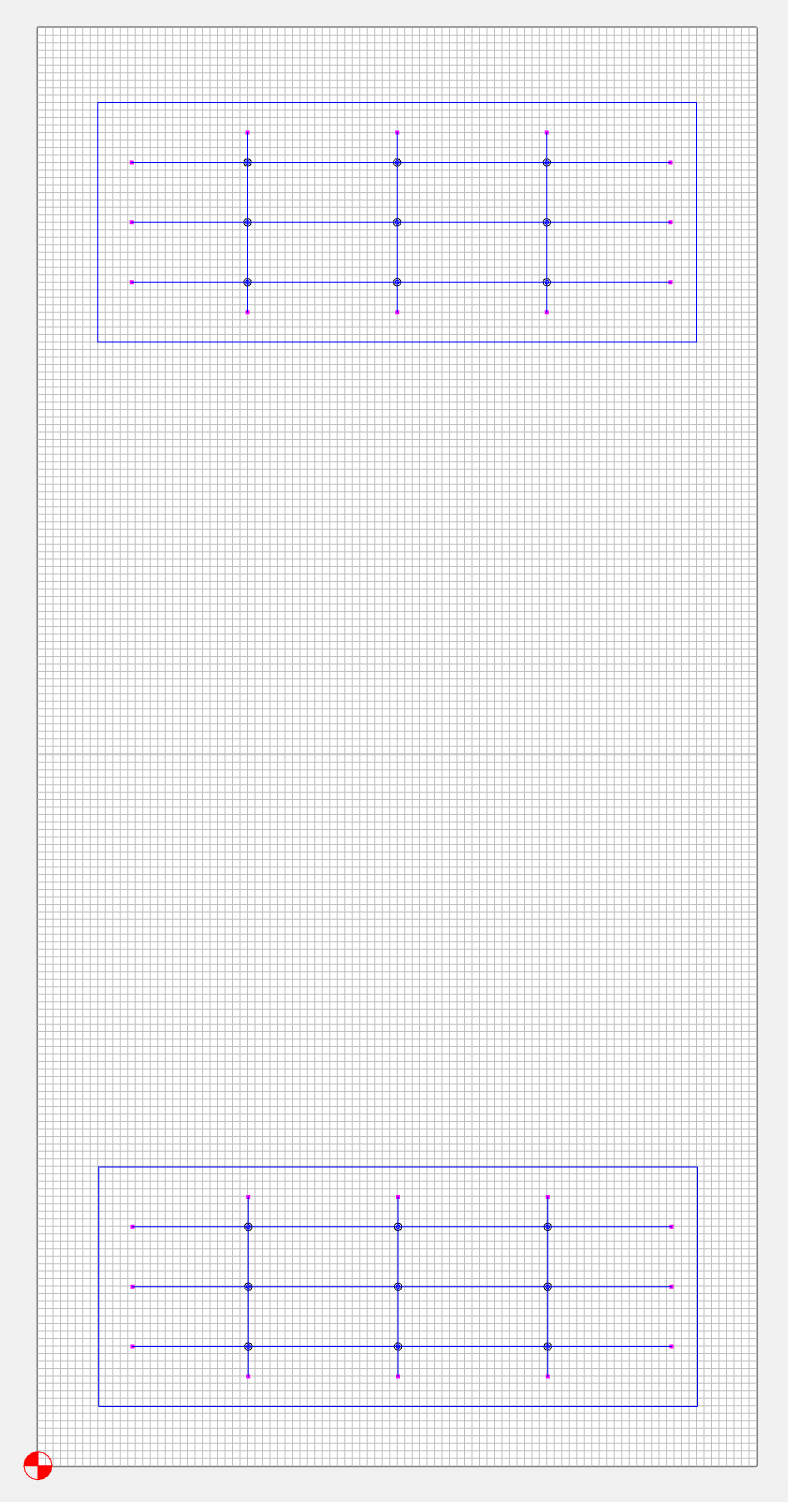
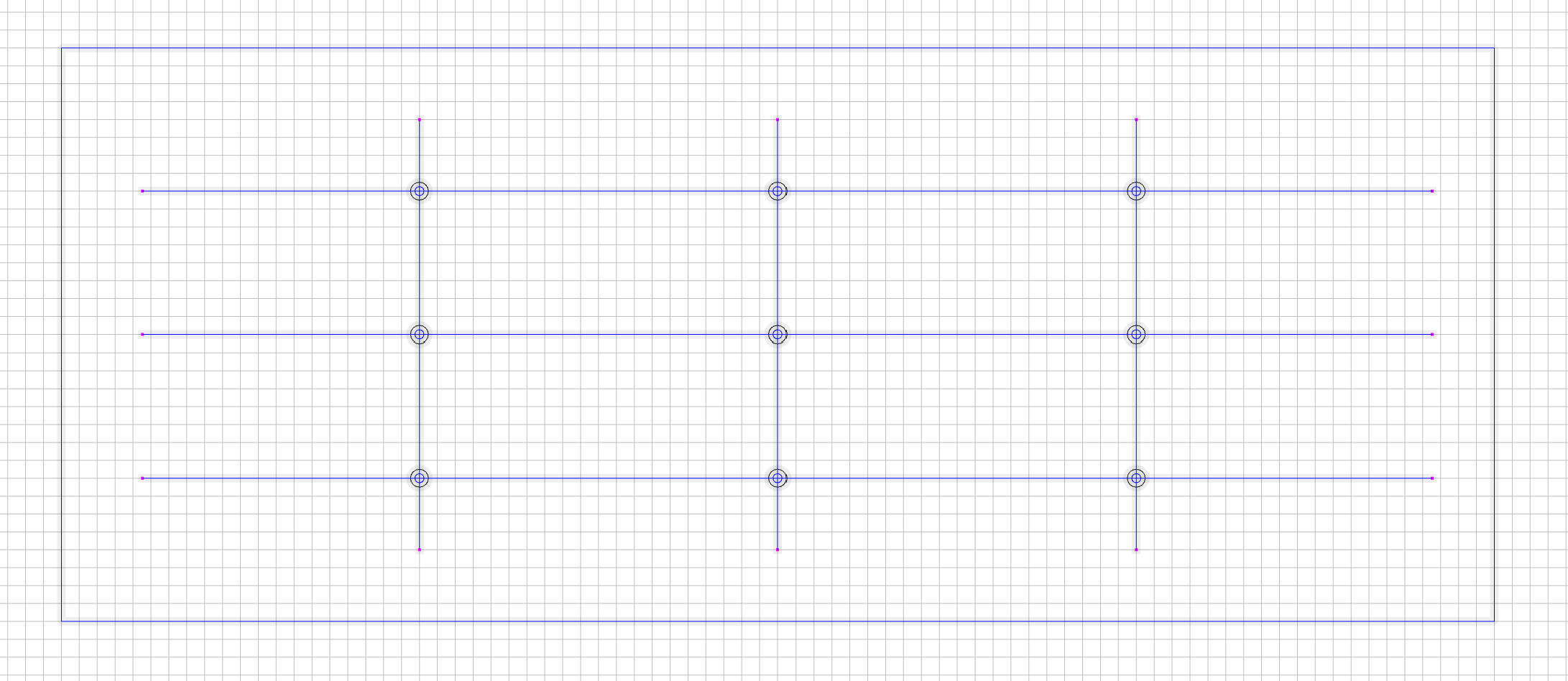
I took you and @mhotchin up on the squaring and designed the following on a 2’x4" sheet of 1/8" ply. Each 20"x8" rectangle gets cut at the extreme ends of the Y-axis on the base (full sheet + zoom in).
Result: Perfect alignment of the holes made at the perpendicular intersection of the lines. The rectangles are also perfectly overlapping each other.
One thing I did do before starting the job was to carefully manually push the gantry ALL the way to the very back of the machine (akin to the machine initialization position). Would that have affected anything in terms of fixing the issue??
It shouldn’t have affected anything, because the S5 Pro will attempt to re-square itself relative to the position of the homing switches upon initialization. On older Shapeoko’s however, pushing the gantry to one extent would actually be beneficial, assuming you built the machine relatively square.
The parellelogram-ness of the gantry would not change from front to back. So cutting two test patterns out from different locations and comparing them would not show any difference. You need to flip one of the test pieces over to see the difference. Then you’d probably see the holes not being aligned, and the outer profiles not matching up.
For the most part, yes. Spindle tramming and surfacing your MDF are pretty universal constant in terms of CNC router recommendations. Your Y-axis homing switches should be pretty close to level with each other now, and you might not need to adjust them, but keep that in mind if you’re not satisfied with your results after reassembly. Luke is working on a more step by step guide, so if you run into any issues, feel free to shoot him a DM.