erica
June 28, 2025, 2:25pm
1
I have been asked by my daughter in-law to make a picture frame based on a stl about 8x10
I can import the stl and create an out line vector around the outer but can’s figure out to pt one around the inner to cut that part out.
https://www.dropbox.com/scl/fi/p0kwwoa46zsxbqrdkwkji/33.STL?rlkey=4bkqhyjcolpwd19gr2h5jg6yo&st=zjaz1ah9&dl=0https://www.dropbox.com/scl/fi/p0kwwoa46zsxbqrdkwkji/33.STL?rlkey=4bkqhyjcolpwd19gr2h5jg6yo&st=zjaz1ah9&dl=0
Any direction would be appreciated.
WillAdams
June 28, 2025, 3:36pm
2
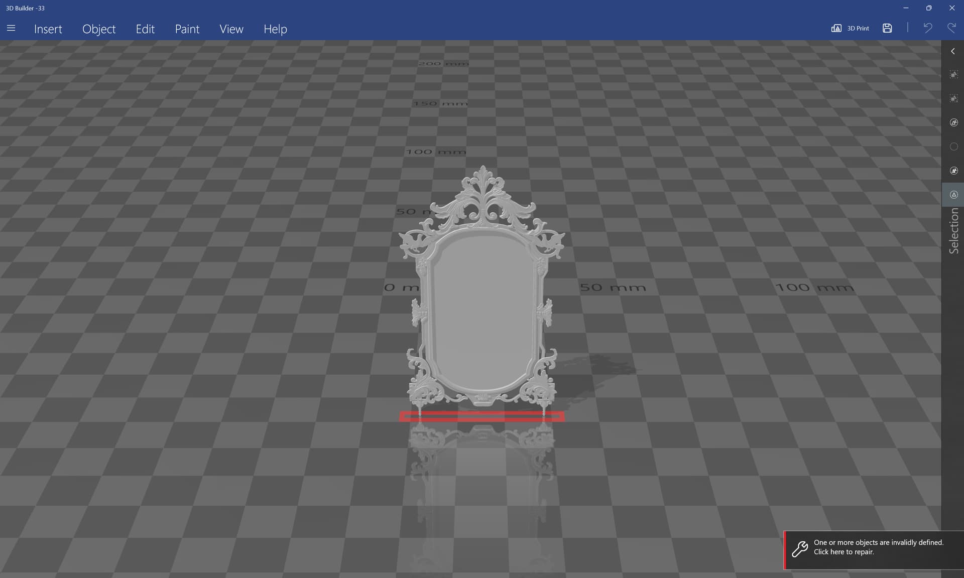
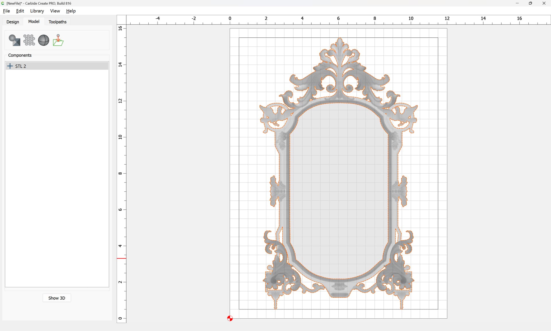
The STL seems straight-forward enough:
(except that it needs to be repaired)
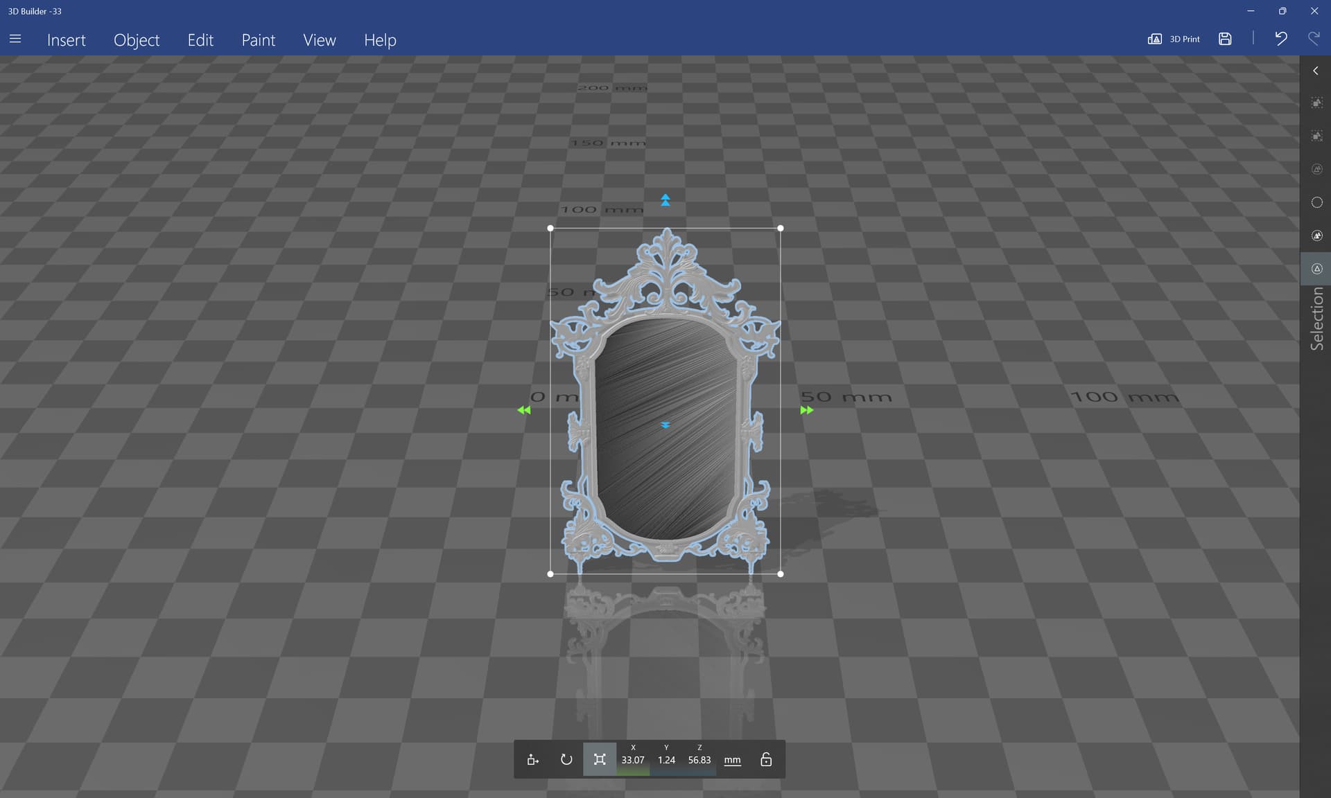
Once it is repaired, the dimensions seem a bit small:
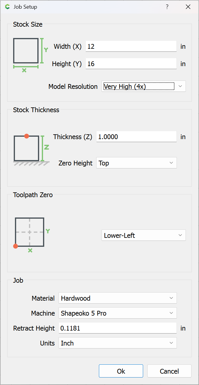
Taking a guess as to proportion/stock size we try:
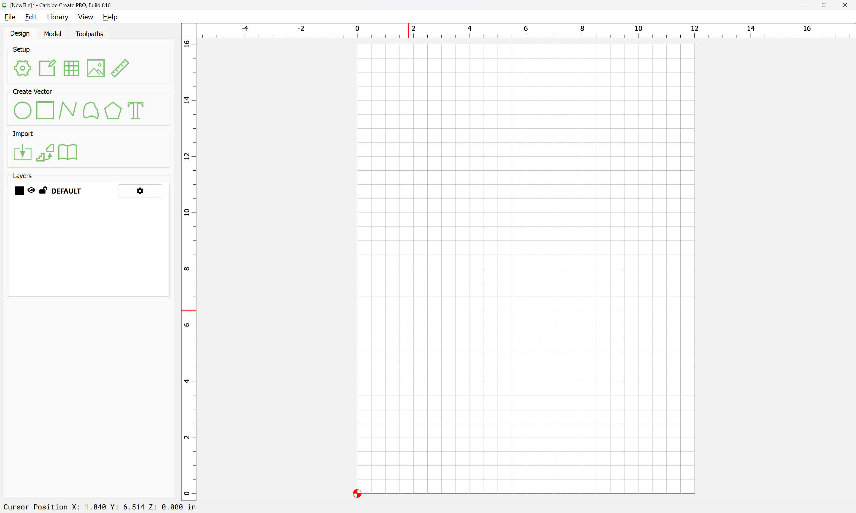
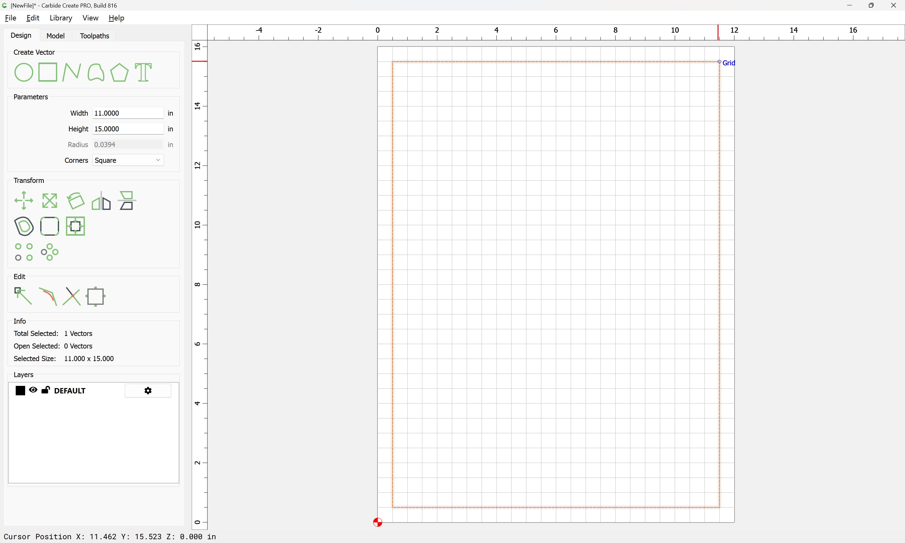
and draw a rectangle:
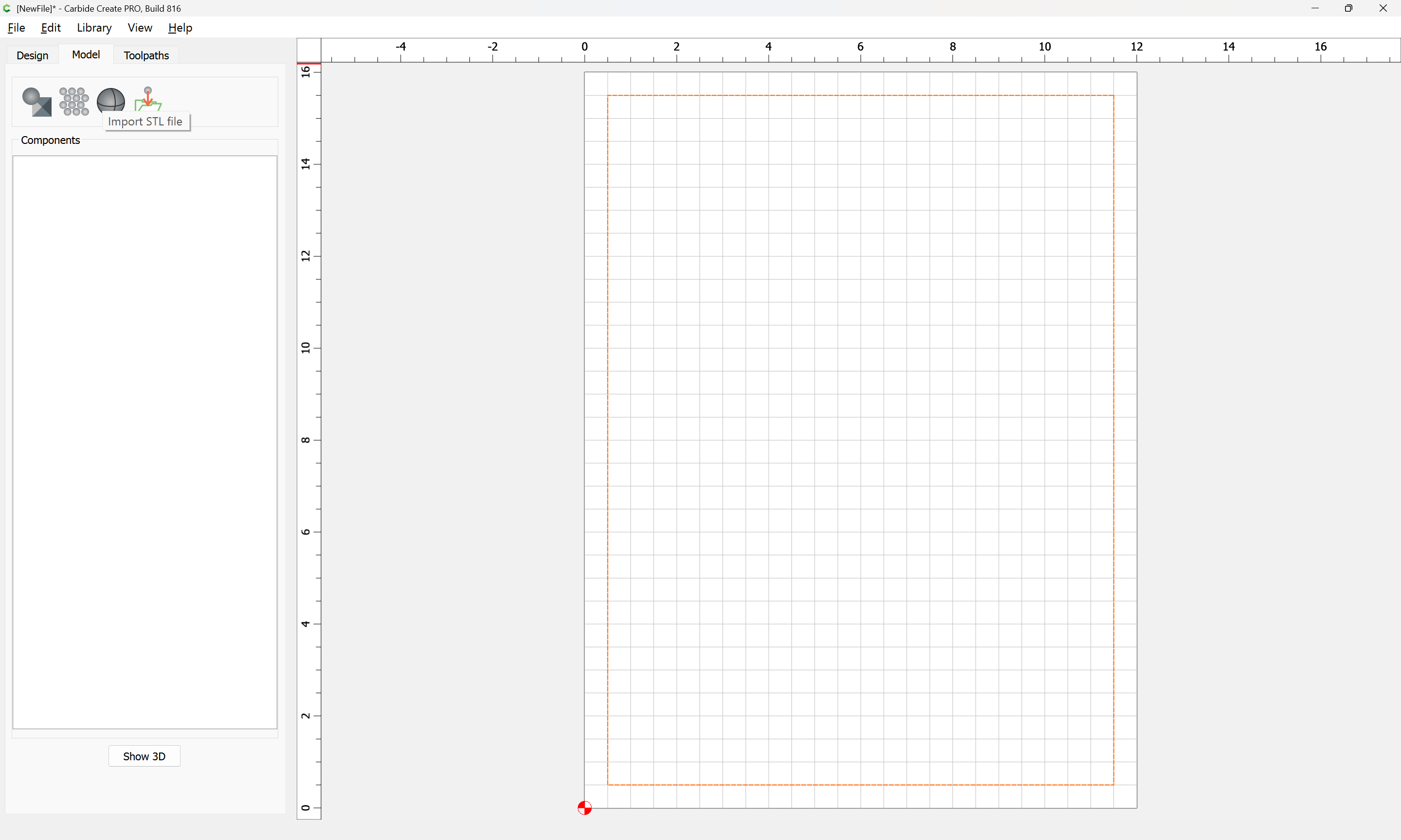
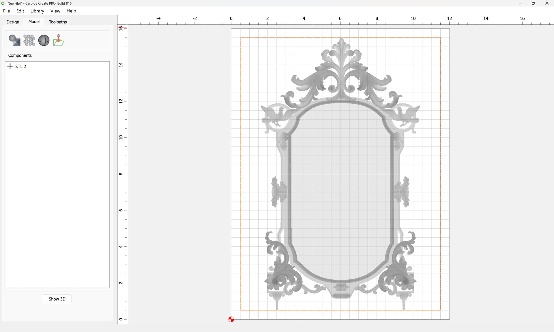
and import the STL into that:
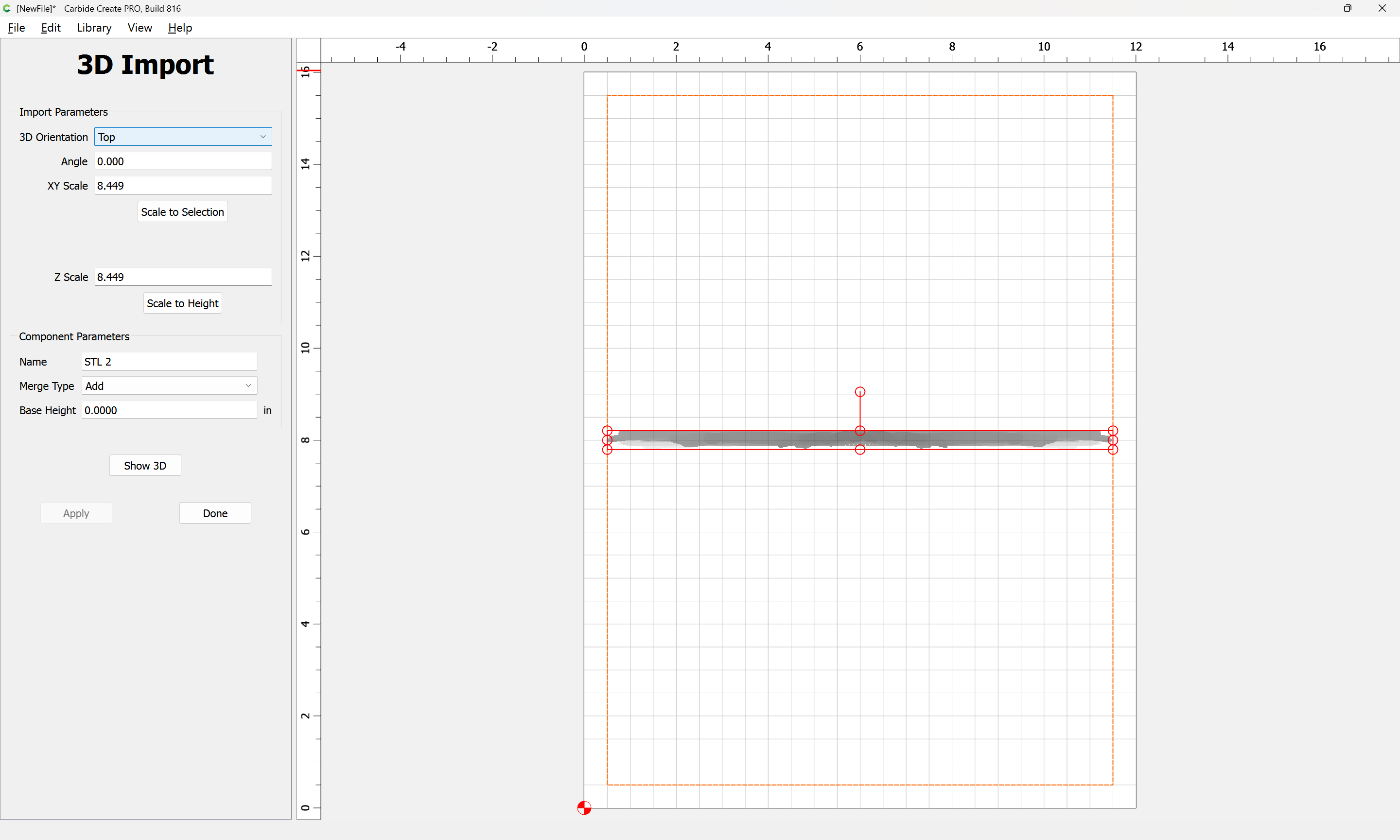
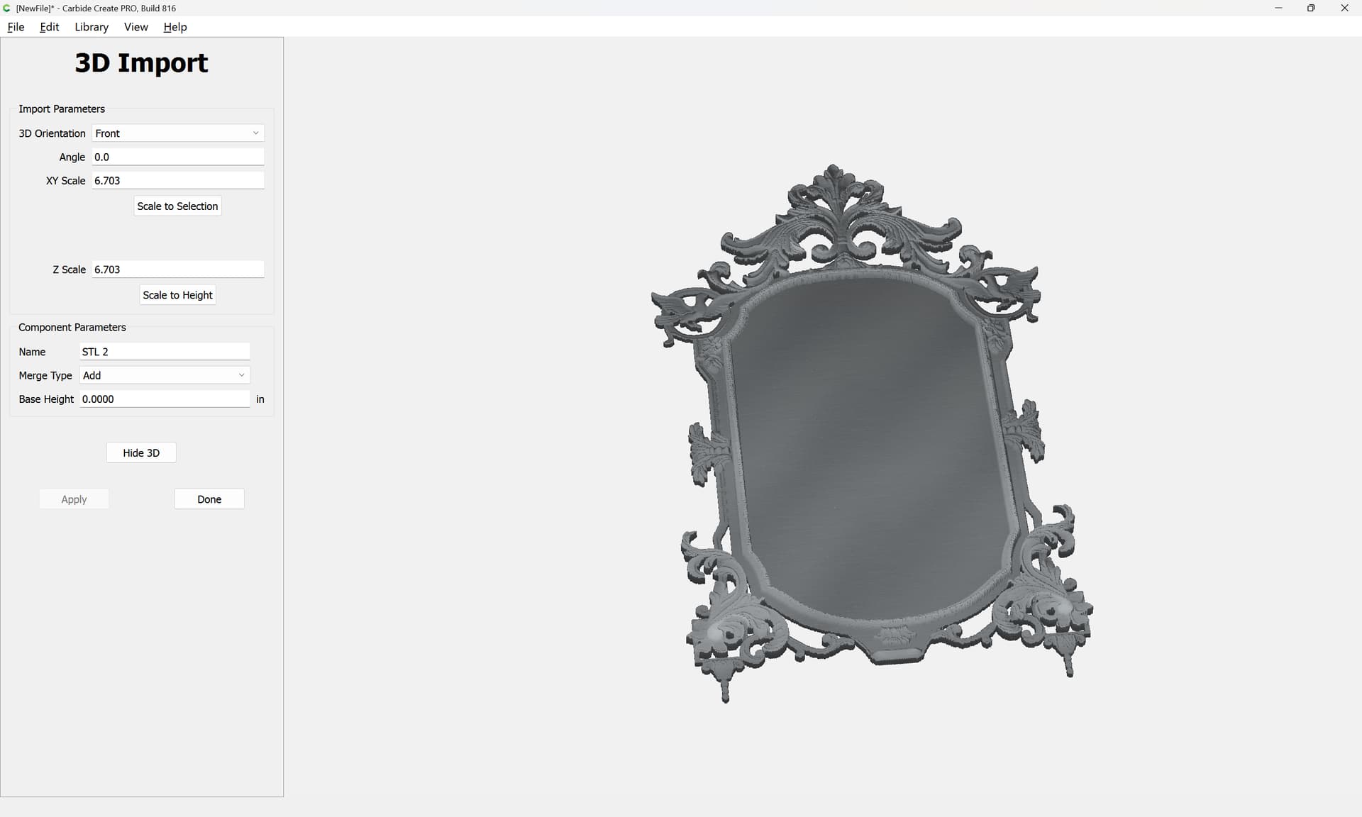
and adjust the settings of the import:
Done
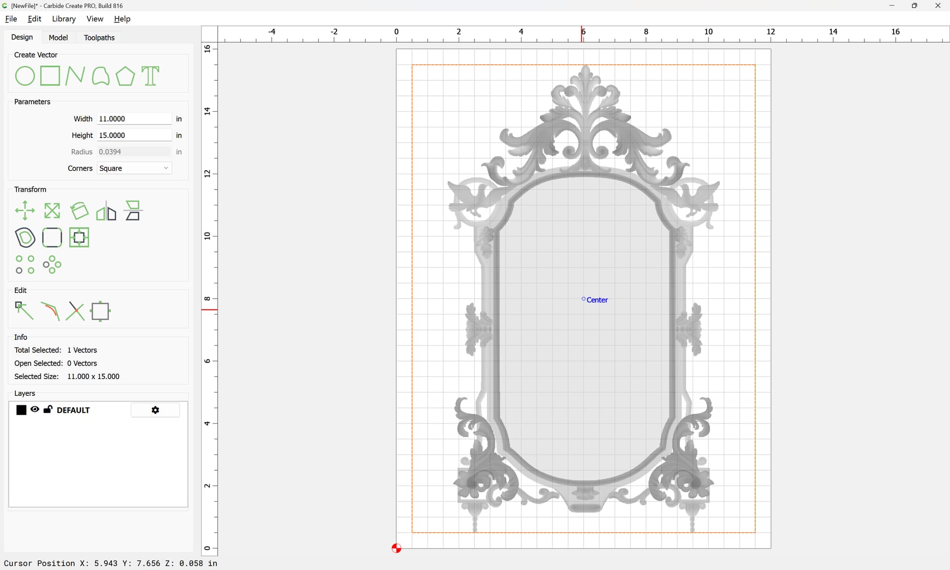
Switching back to the Design tab:
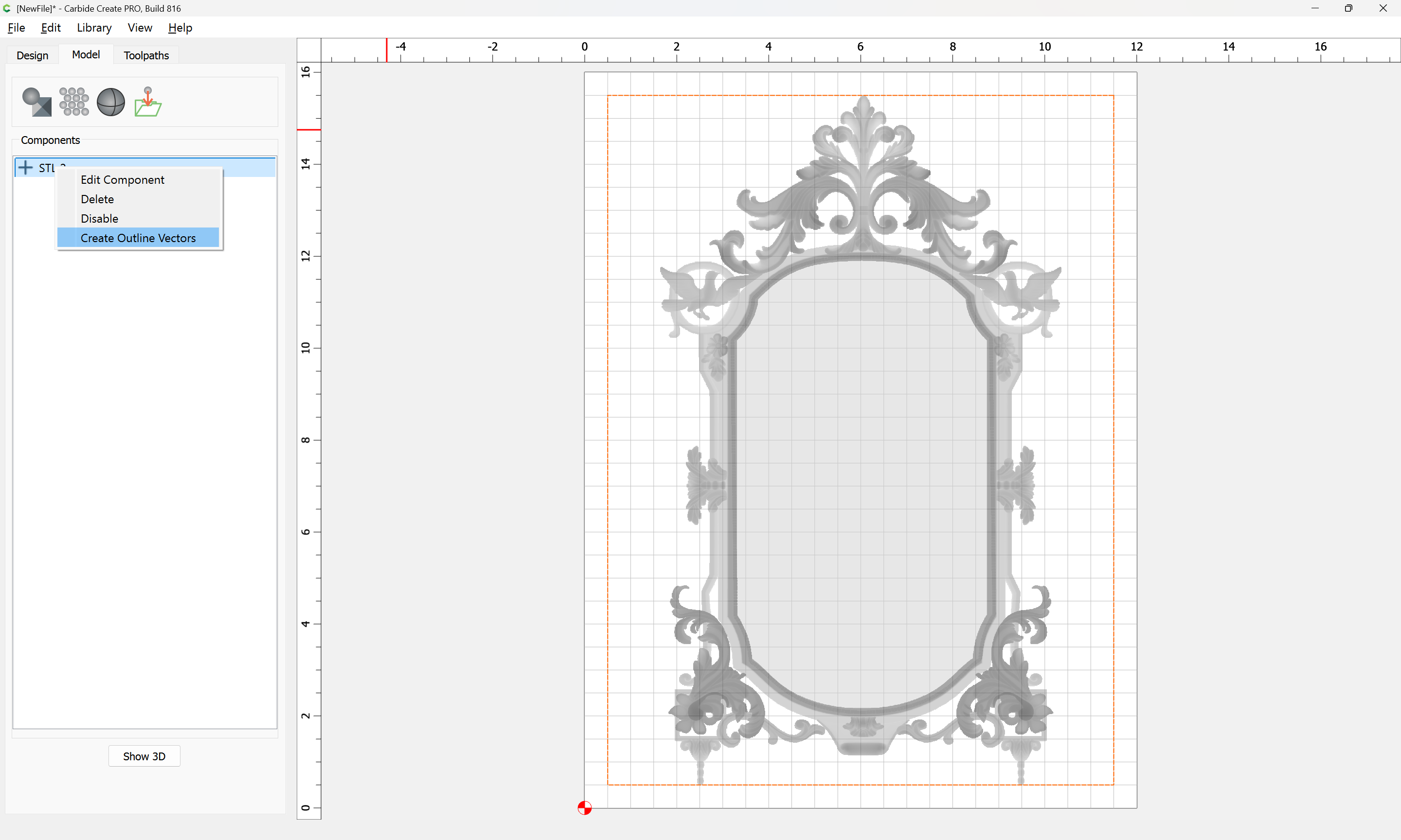
If we mouse over the central area we get a Z-axis height of 0.058 inches — making a note of that we switch back to the Model tab and right-click:
and choose “Create Outline Vectors”
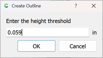
and enter a value just slightly above the height noted
OK
which nets us the interior outline which is wanted if I understood aright.
erica
June 30, 2025, 2:28pm
3
Will, Thanks for the explanation. I had never noticed the cursor position on the bottom left corner of my screen.
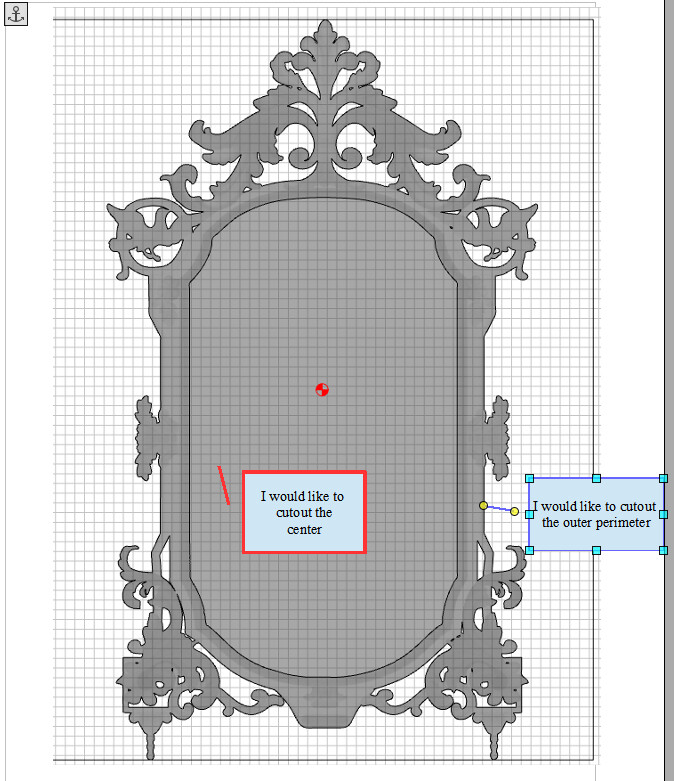
I followed your examples and was able to isolate the interior portion but can’t figure out how to cut the center out completely so I can add a picture from behind. I also cannot see how to do an outer perimeter cut out of the frame.
Is there a way to set two outline vectors? I could then remove unwanted vectors from the inner and contour cut out around that vector and cut the frame outline with the other?
I have tried and don’t know how to set a second outline vector.https://www.dropbox.com/scl/fi/7s9qkfp8az16oe4i20gty/Picure-frame-draft.c2d?rlkey=gekxgbxtrucq255vvmxqur4fb&st=k99svwgd&dl=0
I also increased the base height to thicken the frame.
WillAdams
June 30, 2025, 2:31pm
4
Like most applications, it’s select, then affect — upload a screen grab showing the selection you are making?
Perhaps the techniques in:
While cutting up vacuum extension wands for this is expedient, it’s a bit problematic given that Shop Vac recently filed for bankruptcy, was bought at the last minute, and production hasn’t caught up.
I need a receptacle for the Sweepy 2.0 dust fitting — one option would be to purchase one from Woodcraft, but Carbide 3D sells blocks of HDPE:
which looks to be just barely big enough for things to fit.
Measuring the hose fitting I get a diameter of ~63.5mm — offsetting that twice we arrive at…
and/or
One technique which is often suggested to avoid slotting is to add geometry around a part which one wishes to cut out and cut as a pocket down to tab depth — here’s one technique for that.
In this case, the project is a bevel gauge which will be cut out of 0.0625" (~1.5mm) thick aluminum:
[bevelgauge]
Due to the narrowness of the angles, an 0.03125" endmill has to be used, so after importing and scaling the file (we will be cutting out one which is 3") we select the perimeter and offset it tw…
and consider leaving a roughing clearance and taking a finishing pass.
One which has a cutting flute length equal to or greater than the thickness of the stock — pretty much any tool should work.
Big thing is the toolpaths — if cutting out, rather than just cutting a slot:
[image]
Offset to the outside by endmill diameter plus 10% or so:
[image]
[image]
[image]
Then cut as a pocket:
[image]
down to tab height or the penultimate pass:
[image]
then move the contour down to below the pocket and start cutting at the bottom of the pocket:
[image]
and…
erica
June 30, 2025, 2:59pm
5
Will, based upon your answer, I am not sure I worded my question properly.
system
July 28, 2025, 2:25pm
6
This topic was automatically closed after 30 days. New replies are no longer allowed.