Yep, that’s definitely the case. It’s quite loud too, even with the enclosure that makes lighter cuts near-silent.
Sorry, should be fixed.
No, not that I’m aware of. There are only 3 wires going back to the McGillicutty so I think it can be doing that.
You mean it’s expected for the speed to drop?
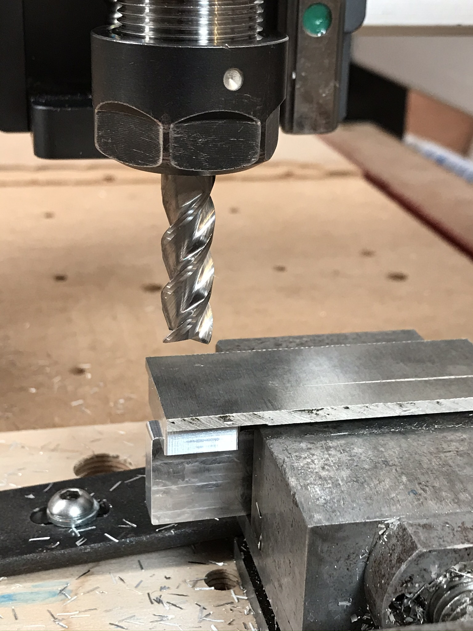
Yep, the Carbide 3D precision vise, though that’s attached to a heavy chunk of Aluminium with T-slots cut into it. I can try attaching the vise directly to the Nomad’s bed as well but I fear that will make things worse.
I also have a bunch of T-slot clamps, do you think it’d be worth trying those out?
I think the Aluminium bed I’m using is already quite heavy so it should have the same effect.
I suspect what I really need to do is just get a better vise.
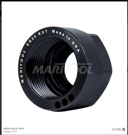
Or it could be, as Vince suggests, that the anti-backlash nuts are too weak. No matter what I do to the bed, if the nut isn’t properly rigid, there’s going to be vibration.
There are clearly multiple sources of deflection and vibration in the machine. Which of them to fix in which order for the greatest benefit is the million dollar question. Given the number of mods Vince has made and his quality of work output, I’d give his suggestions a significant weighting in my decision process about what to upgrade to get the desired performance.
I’ve spent a fair amount of time measuring relative movement of parts of my XXL with a dial gauge on a mount. That has really helped understand what is deflecting but it’s also given me a baseline to do really rapid checks of whether the machine is “normal” or something is getting loose. I know the collet slack and deflection I expect for 5kg force at the collet in X and Y so I can very quickly check if things are OK.
From what he’s said, the ballscrews seem to be among the most impactful, though I think the linear rails on Z are a big deal too.
I’ll try out some new workholding tomorrow though. The thing that makes me hopeful is that the 1.5mm cut had a decent chunk of time where everything was calm and the 1.5mm cut was only taking ~2.1A. If the issues were due to an inherent flaw in the frame, they should have been persistent throughout the entire cut, but they weren’t.
So I’ll try throwing a bunch of clamps at it, which should make it much harder to lift out.
The other thing that makes me hopeful is that at 1.5mm, if I’m still only using 2.1A, that’s only 50W, so I’ve still got quite a bit of headroom, especially given that 1.2mm was 2A. If things are linear, 0.1A bought me 0.3mm depth and I’ve still got 0.9A left, which could mean an extra 2.7mm, for a total depth of 4.2mm.
At 4.2mm, it’d actually be doing what Millalyzer claims takes 48W, which would be a big efficiency improvement on the numbers I’ve seen so far.
Of course, I have serious doubts that the machine will be able to do that. I suspect it won’t be rigid enough, but I can dream.
Anyhow, I think I’ll try following in Vince’s footsteps and add ballscrews to all axes and linear rails to the Z-axis. That ultimately shouldn’t be too big a project:
Adapter plates for the ballscrew nuts
4 precision milled but small plates for the Z-axis:
One plate flush against the X-axis carriage with the linear rails attached
Two plates that screw into the top and bottom of the X-axis carriage as well as the top and bottom of the plate with rails
One plate to hold the actual spindle, attached to the linear rail carriages
Something to attach the Z-axis to the ballscrew nut
@Vince.Fab can you share any details about your ballscrew nut adapters You said they were “close”. Do you think it’ll be any real trouble for me to machine? Did you make them from Aluminium or steel?
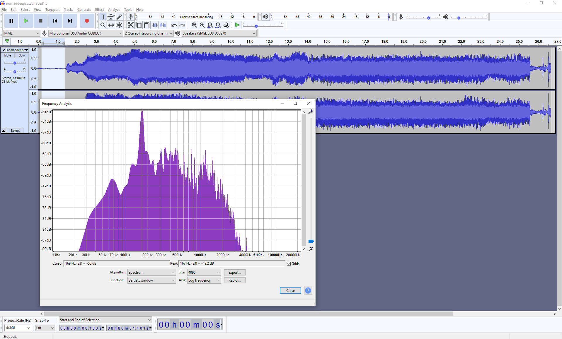
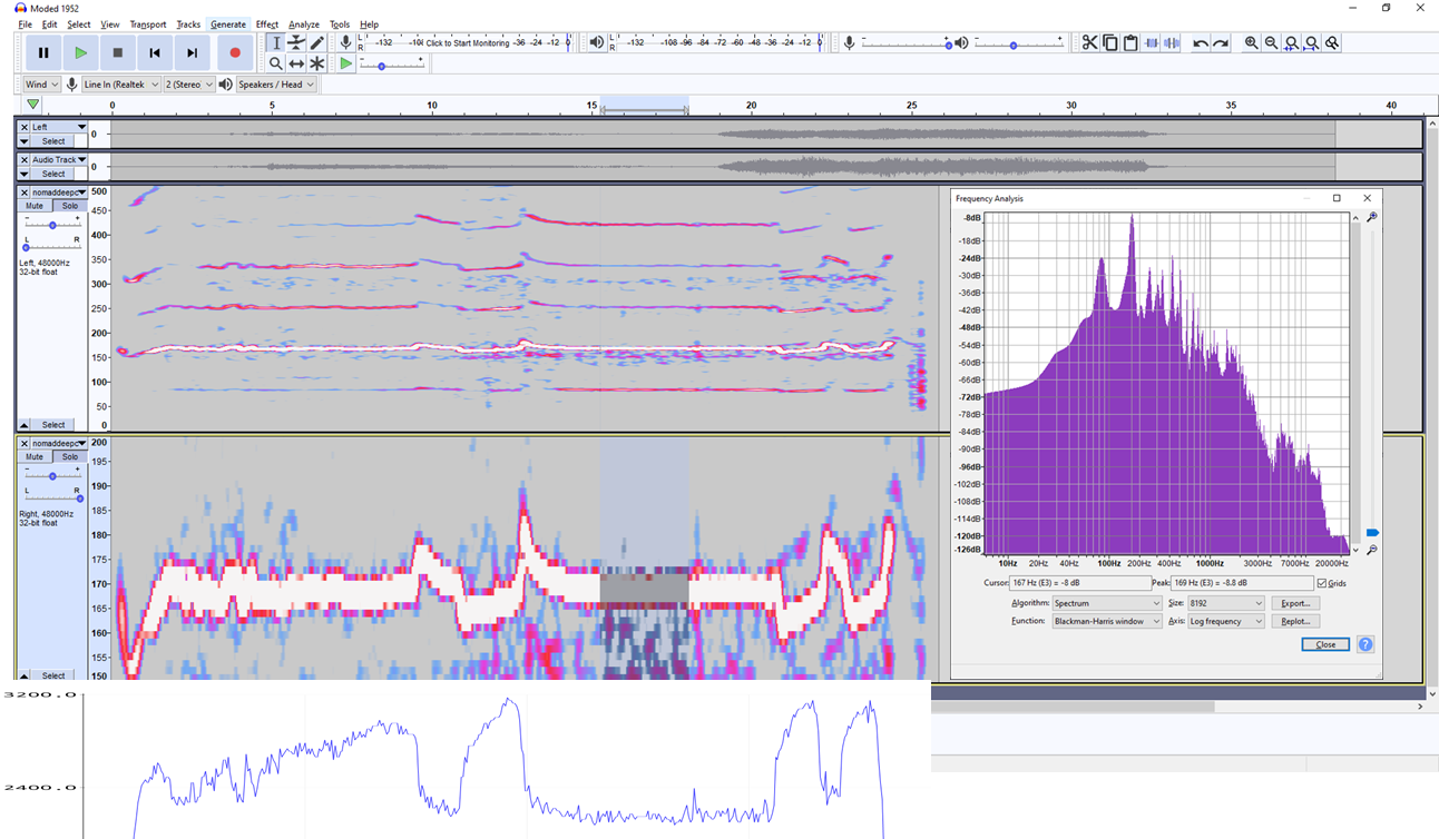
I grabbed the audio of your 1.5mm cut file in Audaticy (as @gmack did above), it’s really worth a download (it’s free).
In the lead-in before the cut we can see the main frequency peak around 169Hz, is this running at 10kRPM?
Note there is little noise around this peak, there’s some rattle and hum from the machine above the base frequency of the spindle (and there’s presumably some gearing between the motor and spindle, any idea what ratio?) but there’s very little below the cutter frequency;
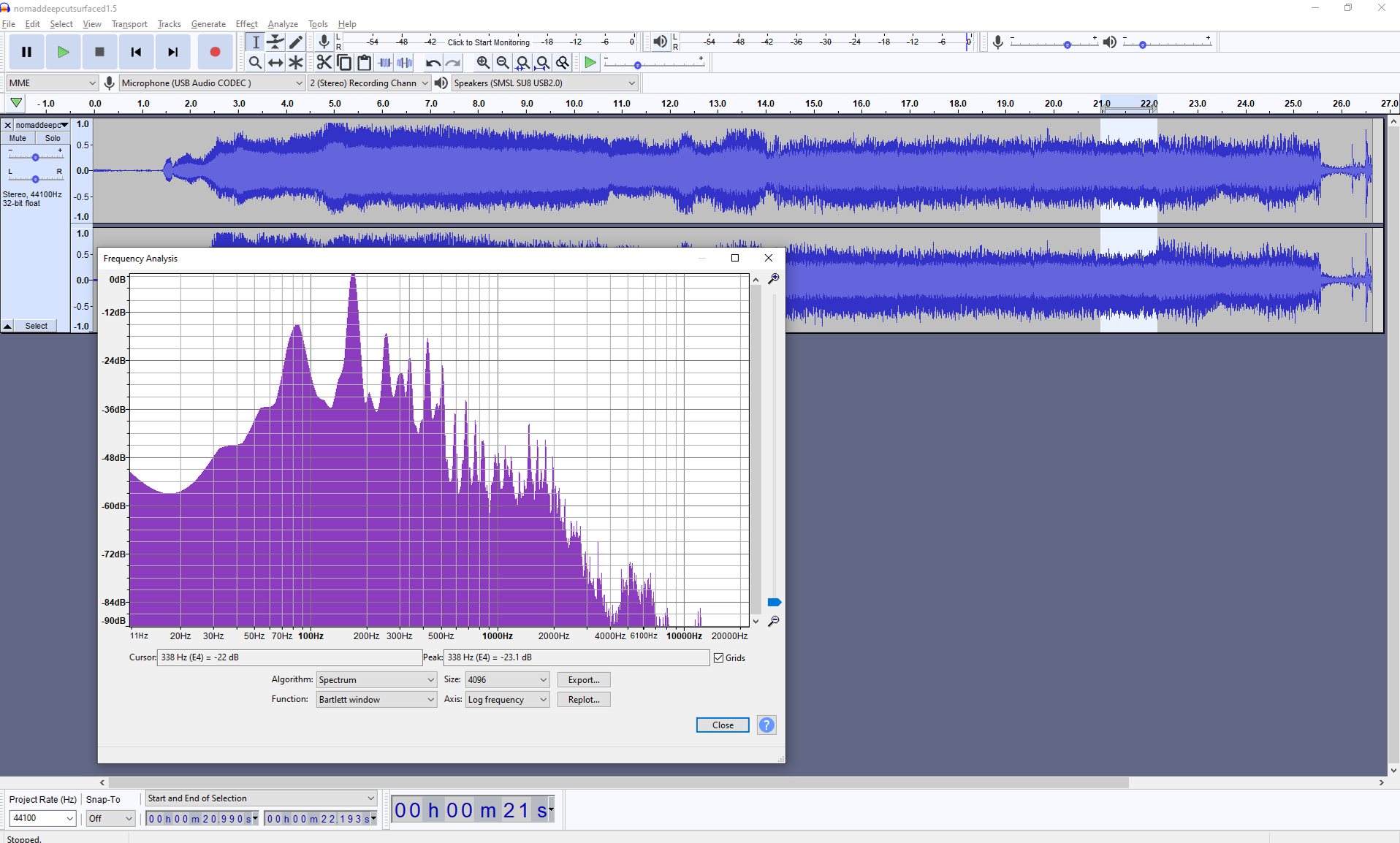
Here’s one in the first part of the cut, note that we’ve gone up 50dB and brought the low frequency noise up by >> 40dB. That’s significant because it’s below the cutter frequency and indicates that we’re exciting other vibration modes.
We’ve also picked up a whole load of high frequency noise from assorted vibrations.
We have the first harmonic of the (single flute cutter at 10kRPM?) at ~340Hz now, the further harmonics are mostly lost in noise.
And later in the cut, this picks out the 338Hz first harmonic of the cutter, but we’re also seeing a substantial peak at ~83Hz which is the first subharmonic (is the belt drive a 2:1 gearing?)
Some of this will be down to the other linear motion parts of the machine but it would be interesting to compare these spectra with a “clean” cut where the machine isn’t trying to shake itself to bits.
It’s going to be a step at a time, it would be really interesting to get a series of base measurements for deflections and backlash on the machine along with some spectra and power data for repeatable cuts to test progress…
That I can do. I’ll do the same everything but just drop the axial engagement down to 0.2mm.
I can do the spectra easily enough. Regular backlash, I’ve already measured and compensated for in my controller. I haven’t tested stiffness of the AB nuts though. Power I can also do.
Maybe for power, I should record progressively deeper cuts and see if I can plot them on a graph and produce a curve. It’d be really interesting, even if only to see if it’s linear or not. It’d also be interesting to see how the curve changes when ballscrews etc. have been added.
Oh and for spectra, I should put a microphone in the enclosure and/or a few accelerometers scattered around the machine… Maybe I’m getting into overkill territory though (or “so much work that I’ll never actually get around to it” territory).
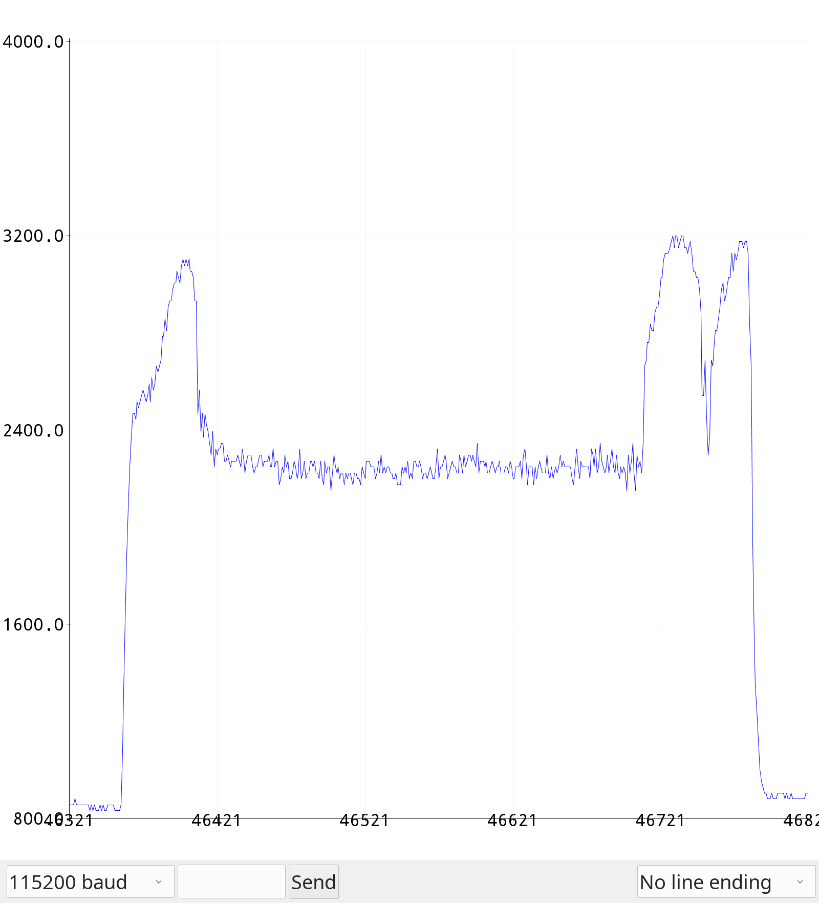
It looks to me like the sensor-less motor controller is doing a pretty good job maintaining speed, as it should. Apparently the motor isn’t the problem. Sure wish we could see the motor currents!
Yes, the frequency didn’t move much, I think it’s the changes in harmonics and the lower frequency other vibrations that appear during the cut that create the audible effect of a larger slowdown than is really happening.
I’m not sure what’s going on toward the end though.
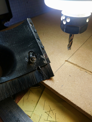
Also, I noticed that the dancing chips only dance on the Aluminium composite cover. On the Y-axis bed itself, they’re completely still, so it’s not the entire machine that’s vibrating that intensely, just the lightweight cover.
I’ve been thinking of removing the cover and this makes it just that little bit more appealing…
I didn’t understand this bit, do you mean that the clamps put more force on the stock where the endmill is cutting around the start and end of the cut?
Pfew, that’s a lot of data to look at, thanks so much!
So do I get this right: About 900 mA or so out-of-cut and 2250 mA while cutting? That would be 32.4 W additional electric power draw at the input side of the speed controller? With the efficiencies that @LiamN and @gmack mentioned earlier, that would yield somewhere in the range 20 - 25 W mechanical. Millalyzer says 14.5 W for a very sharp tool and 18 W for a mediocre one at nominal conditions.
Since this is a 1-flute, I have doubts whether it will survive more than AP 2 mm for long (tool bending stress).
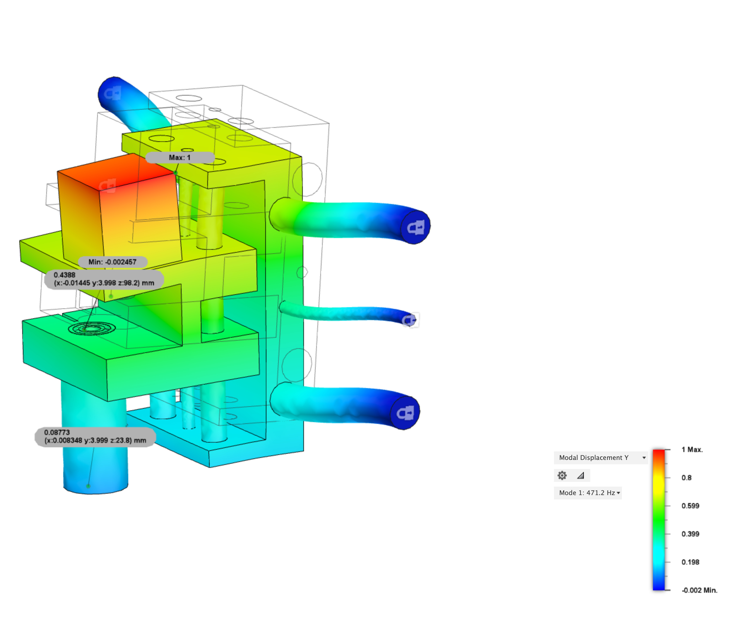
The spectrum for the AP 1.5 mm shows a response at 253 Hz and one at 422 Hz which I can’t associate, even in the middle segment, so this could be the culprit. 400 Hz wouldn’t be unlikely for a structural eigenmode of such a small machine, actually. Then again, this is sound, not motion…
Hmm, I just got a new batch of endmills, a few of which are Hartner, so have well-defined geometries. Would it be more helpful to cut with one of these?
I’m also curious just to see what difference different endmills make in general…
I’ve got some beefier endmills. I have multi-flute 3mm endmills. I’m curious to see what would happen with 6mm endmills in particular, since I can actually reach closer to manufacturer-specified surface speed with those.
Just spitballing here but could these sounds come from the vibrating Aluminium composite covers? I notice them vibrating pretty seriously.
Gravity (or space-time curvature, I’ve heard gravity no longer exists).
The machine is in a 10mm-thick MDF box inside another 10mm-thick MDF box. Both boxes are lined with this stuff on the walls and roof. The Nomad, the inner box and the outer box each sit on strips of this stuff.
There are two 6mm-thick plates of polycarbonate that replace the front wall of both boxes.
The whole assembly is sitting on top of an IKEA standing desk, which is usually in standing position (and a bit wobbly as a result).
If you need exact measurements for anything here, I have most of them on hand.
Oh and all recordings are taken from outside the enclosure.
If you want and it’s helpful, I can give you more accurate measurements.