I would like to use a dust boot on the Nomad3 to help manage particulate while cutting metal.
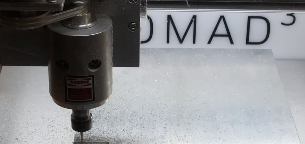
The design from 3D Printed Nomad 3 Dust Boot w/ Brush seems to fit a different Nomad3 than I have. Winston’s design is for a rectangular feature (spindle housing?), whereas my Nomad3 has a cylindrical feature.
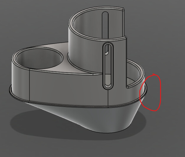
@Radiation thanks for the prompt response, and sharing the fusion file. I see only the bottom component in the online viewer (I may be using the online viewer incorrectly)
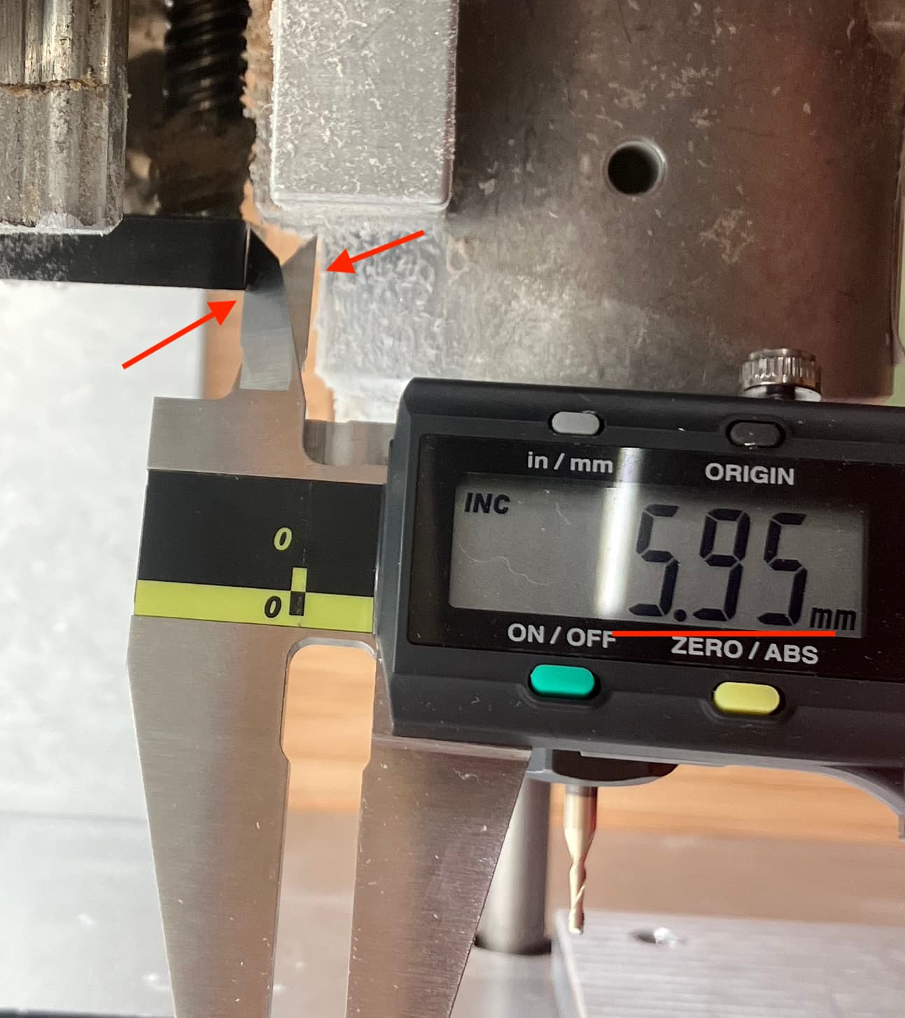
Are there shareable, dimensioned drawings of the spindle and adjacent mechanical features? This could help avoid a reverse engineering effort, and guess/check cycles.
Dust boot is the piece that goes on the spindle.
Shoe is the piece that connects. Like I said you should modify it to remove the back lip. Otherwise worked fine. Got lazy and didn’t make anything for bristles, but I assume someone can use this as a starting point and come up with something better.
Sketch dimensions above.
For bristles, I’ve been cutting up a roll of transparent shelf liner, or sheets of transparency film (as used to be used w/ a projector — the latter can be cut w/ a Stingray…)
When I was testing dust boots awhile back this was recommended to me and it printed pretty well while maintaining good conductivity. Essentially it electrically couples your vacuum boot to your machine. A nice ground path for any rambunctious pixies.
Just add an ESD safe vacuum hose and you should have a decently ESD safe setup.
@HeuristicBishop, thanks for the advice on ESD safe options. That is an interesting design constraint (parts selection, hose bend radius, enclosed operation area)
I drafted & printed an experimental vacuum hose adapter.
It has a few design elements:
Threads for direct hose attachment. This saves space by removing off-the-shelf press-fit rotating hose adapter supplied with hose kit. In the future, this allows for better coupling of ESD-safe hose with ESD-safe dust-boot. However, the hose will no longer rotate during motion which needs managed elsewhere. Note: with 2-axis motion of the spindle, rotation of the hose is minor.
Air inlet faces the location of the cutter. This is analgous to hand-holding a vacuum wand during operation. I’ve not used a dust-boot before, so unclear how this compares to the “360 surround” inlet design.
Two piece construction is held by press fit. No magnets. However this implementation is not robust.
Complicated geometry looks impressive, but adds material waste during simple 3d printing.
Going all the way around the cutting tool seems to help a lot. Bristles coming down from the boot also helps a ton by simply being a wall for things to hit and fall down.
I think strips of bristle brush can be bought from McMaster or similar retailers. Maybe worth wrapping your boot around the spindle and dropping some brushes down from it.
I had a(n unofficial and unsupported) concept that I didn’t get a chance to test thoroughly, but it’s meant to be used similar to how my original design was - Thumbscrew on the sides to secure height (M5, not M4!), Rockler hose in the front angled out, and usable with a flexible strip brush from McMaster. You’re welcome to give it a shot.
Note: The two “nostrils” on top are meant to bleed a little airflow through the base section to help cool the spindle. It’s probably overkill, but wrapping the section of the spindle that already runs 5-10F warmer than the original in a low-conductivity plastic shroud bothered my engineer-brain. (We used larger bearings for greater rigidity compared to the rectangular version of the spindle.)