I just started to run a file which is all pockets except the final cutout. I’m using an 1/8 inch endmill around lettering and when I started the cnc up, it drove the bit straight down to where the collet nut was spinning on top of the material making a burn mark. I have it set to do two passes each at 1/16 depth per pass for a total of 1/8 inch deep. I checked the program again to make sure I didn’t have a decimal in the wrong place or something, but everything looks right. Any ideas?
Could you post the .c2d file?
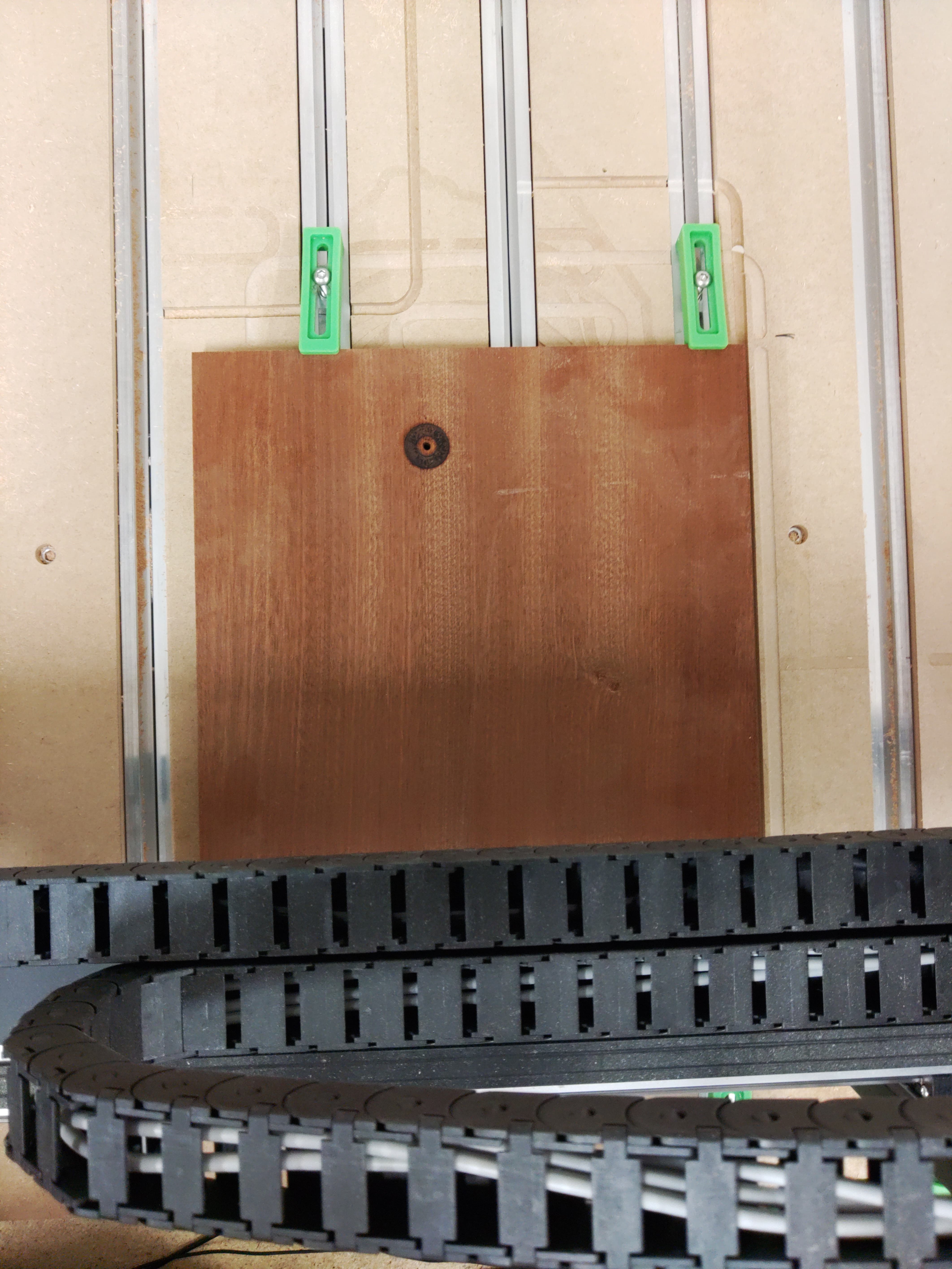
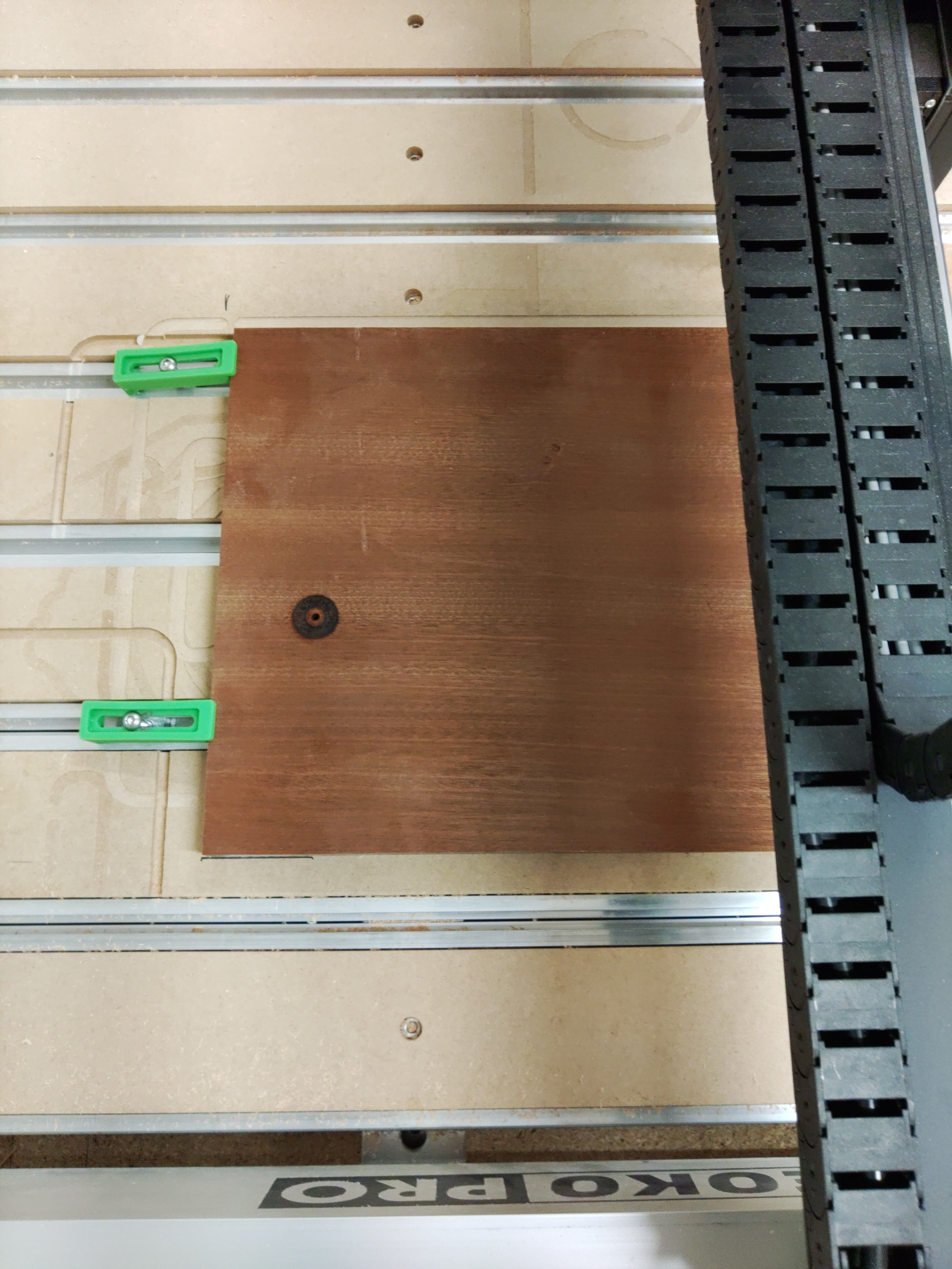
A photo showing the piece still in place on the table?
Were you cutting a slot?
It was the start of the first pocket where it messed up.
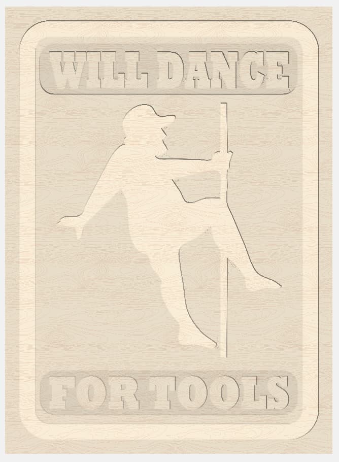
Fat Guy Stripper.c2d (1.1 MB)
How did you set zero relative to the top of the stock?
I used the bit zero. and then measured the tool with the bitsetter.
Do you have the correct BitZero selected in Carbide Motion?
Please see:
I just cut a bunch of plaques out on Tuesday evening with no problem. Set the zero off the top with the bit zero and everything ran perfect. Haven’t done anything to the cnc siince. I set the job up the same as I always do. Did the file look right to you?
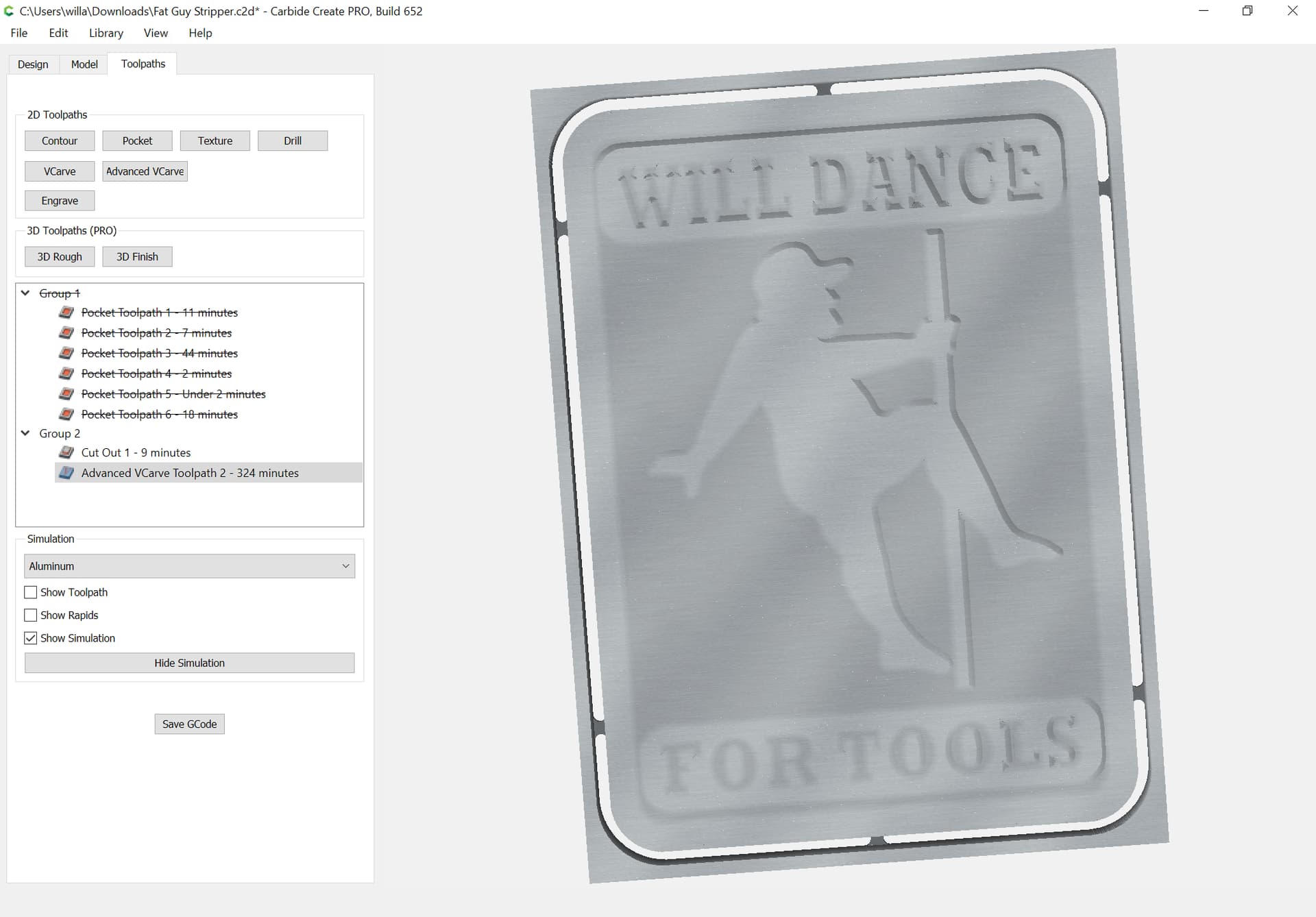
Is this what you want the cut to look like?

I’d suggest using an Advanced V carving instead:
The file seems fine — did you change the tool w/o using the prompt?
Hmm. I’m not sure. I don’t think so. I actually just reloaded the file and tried to run it again. It prompted for a tool change and measured the tool. Still tried to bury into the material though. But yes, that is what it is supposed to look like.
Maybe I should delete the toolpaths and try recreating them. See if that helps.
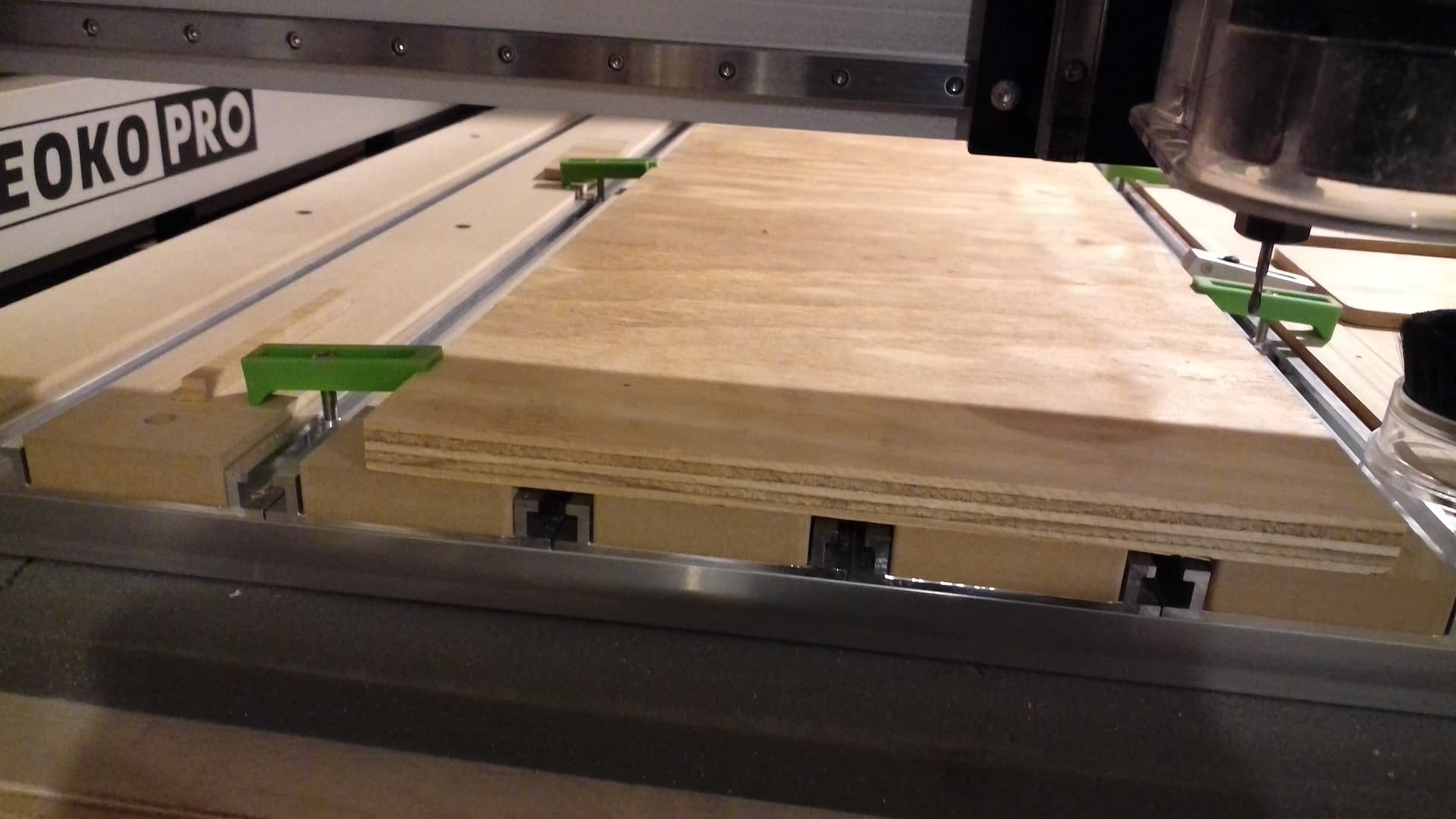
Okay, here’s what I did:
- downloaded the file
- wrote out G-code to fgs.nc
- sent that file to my Raspberry Pi
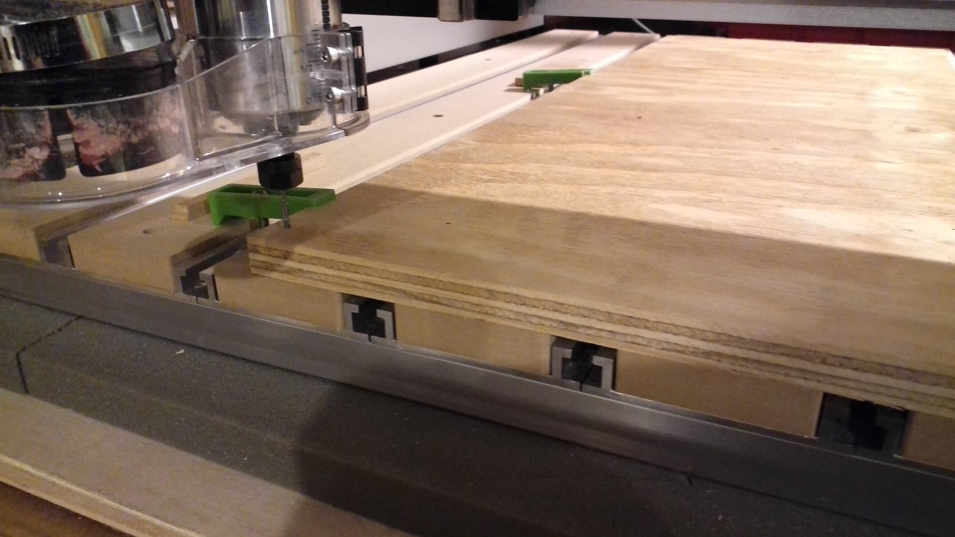
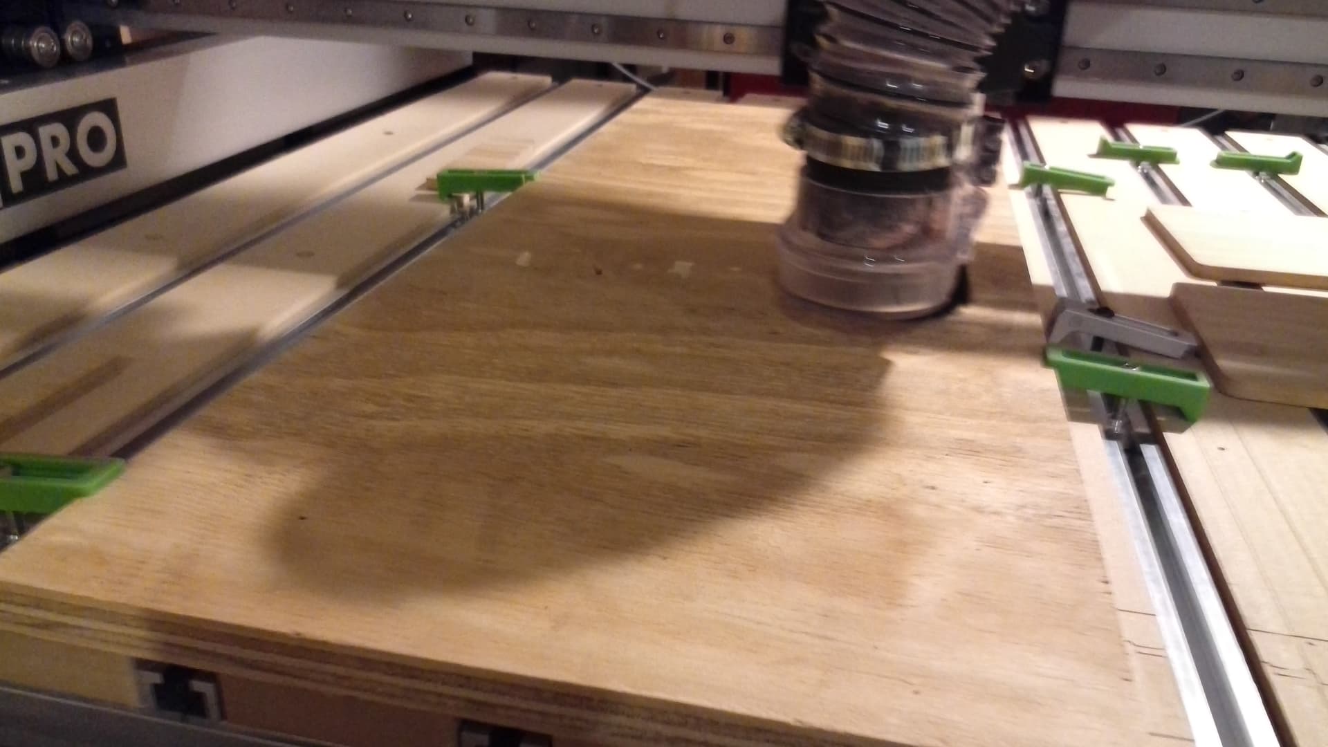
- clamped a larger than stock size piece of plywood in place:
From my experience, I don’t think that will cure it.
Question?? Are you running chip extraction, dust collection? I had issues with EMP. I confirmed it with shutting off my dust collector and running my job.
Here is how I took care of the issue: Grounding your Shapeoko - CNC Machines / Shapeoko - Carbide 3D Community Site
Good luck, ley us know
Powered up and initialized the machine and loaded a 1/8" tool.
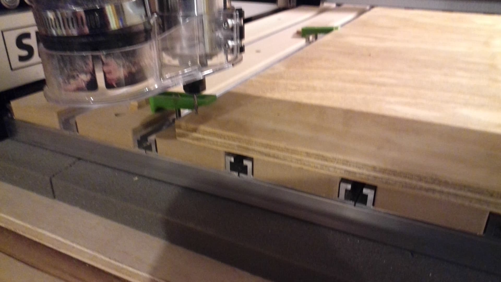
Jogged over to the corner of the stock:
and zeroed X and Y there:
I then placed a BitZero v1 (which CM is configured for) on the stock and connected the ground lead (and tested it):
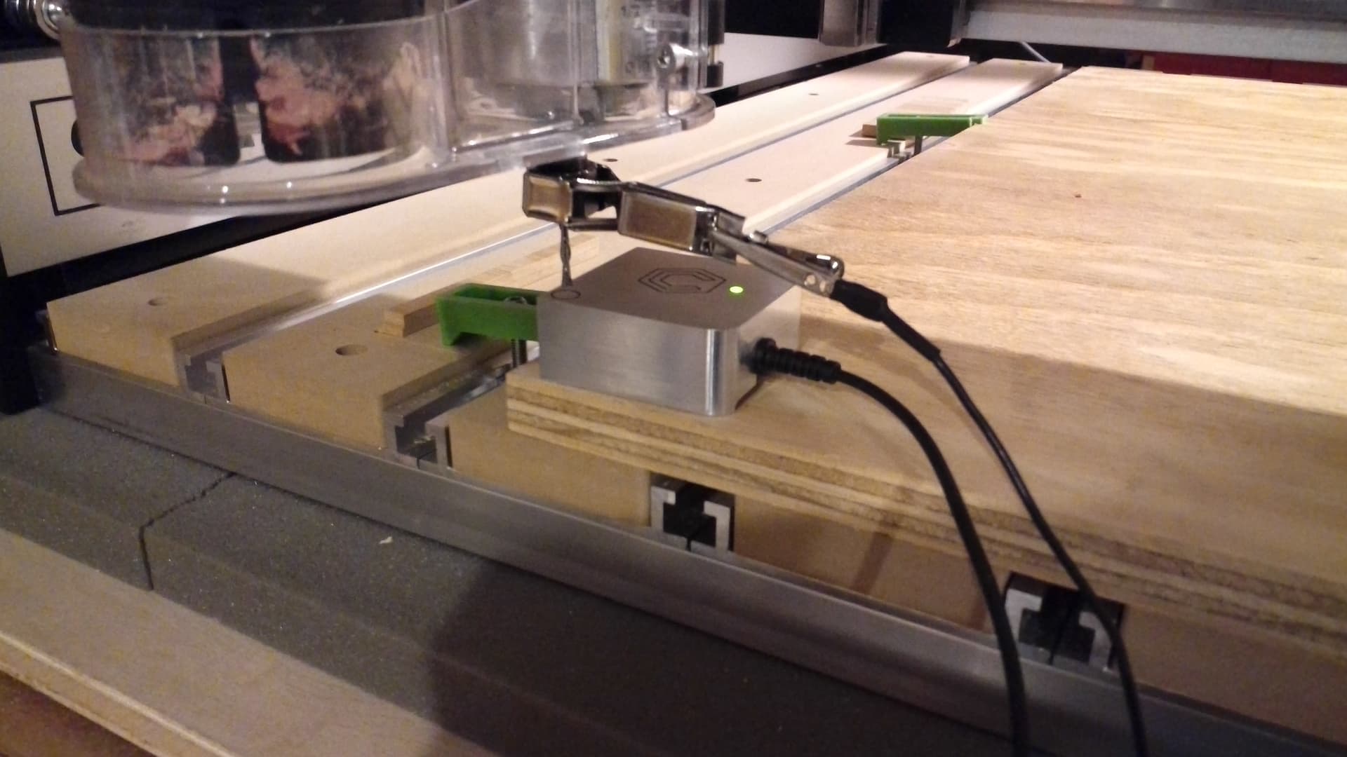
then initiated a probe for only the Z axis:

clicking on “Begin Probe”
the machine then probed for Z
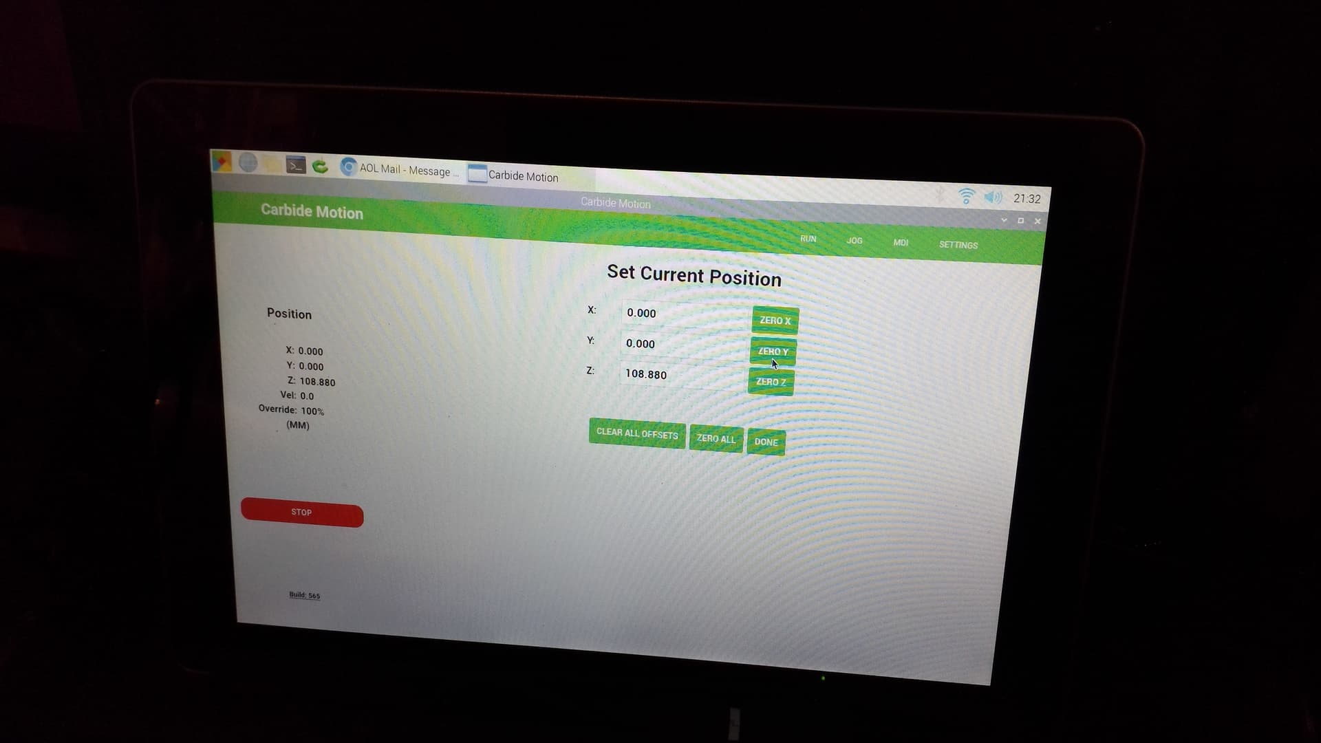
and when I used Rapid Position: RAPID TO CURRENT XY and RAPID TO CURRENT Z + 6mm was at:
click on DONE
go to RUN, click LOAD NEW FILE, choose fgs.nc
and verify how things will cut in the preview:
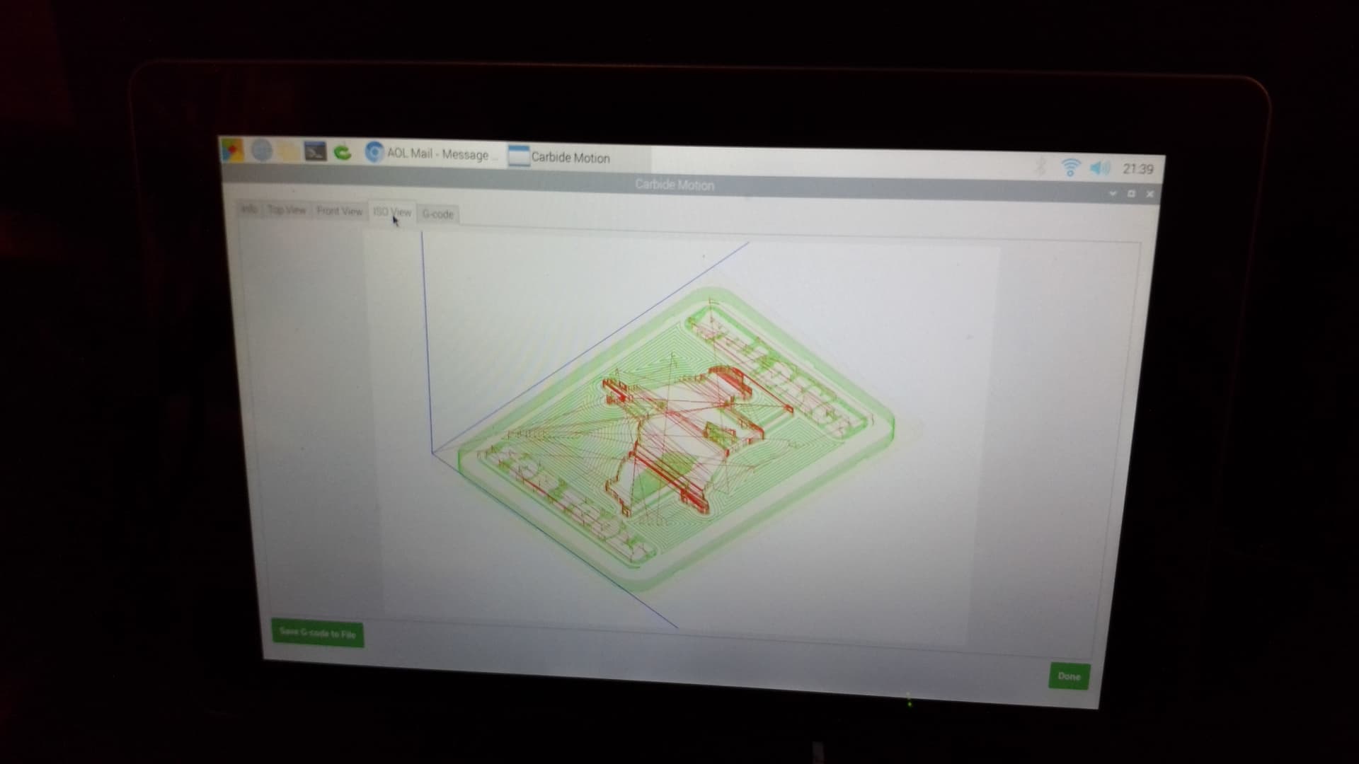
click on DONE, START JOB, START
the machine lifts and comes forward to the tool change position and prompts for a tool change “Please insert tool #6” RESUME
it then measures the tool at the BitSetter — since I have a BitRunner enabled it then begins cutting — which it is now doing:
I don’t understand why you modified the tool or changed the number — things will be much more straight-forward and easier to troubleshoot if you leave things at the defaults, at least until you get a handle on the basics.
Here’s the G-code file which was generated from your file:
fgs.nc (703.2 KB)
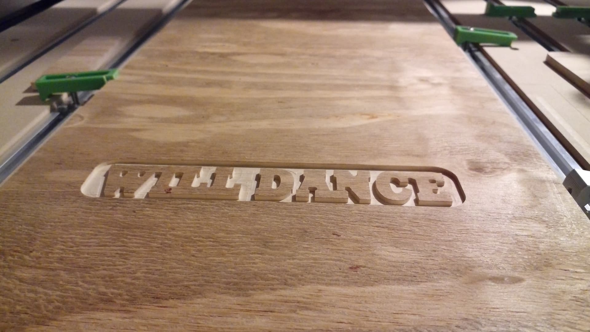
and here’s what the cut of the first pocket (up through the tool change) looked like:
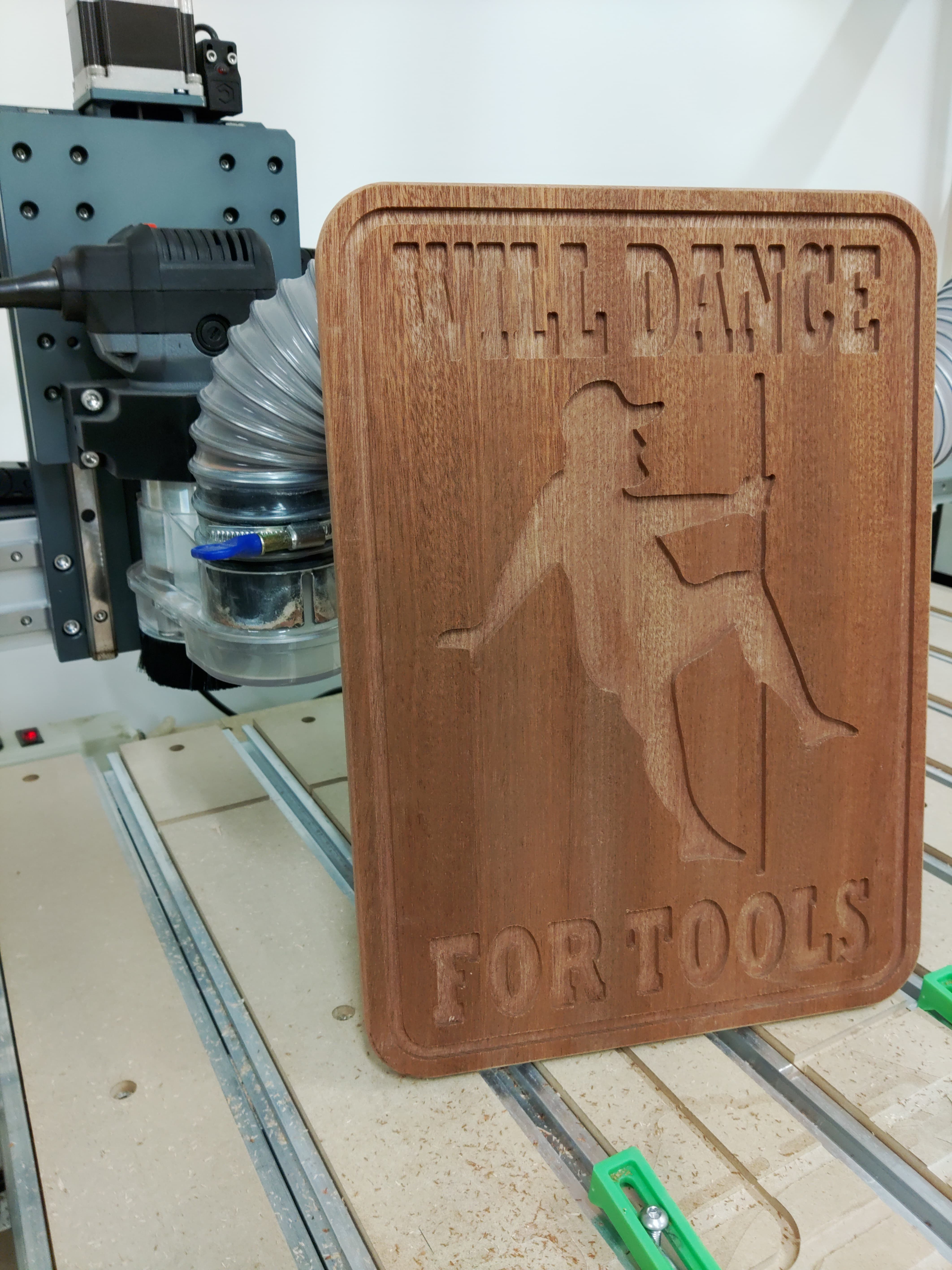
Thank you for all of the help and suggestions. I ended up reversing the pockets to the text and center image along with a border. Saved the gcode, went back through initializing the CNC, resetting zero…basically going through all of the steps just to make sure I didn’t make an error somewhere along the way. And sure enough, I must of done something different on the last run because this time it worked. Cut this out of Mahogany. I’m going to paint the letters and the guy in the middle, then put a nice finish on the woodgrain. I used an 1/8 u.c. and a 1/4 u. c. and it cut really well. Very minimal fuzz and the bottoms of the pockets feel like they’ve been hit with 220. And Will, my buddy set up different tools the ONE time I was able to get about a half hour of his time while he was supposed to be showing me the basics of the software.
1 Like
This is potentially the wrong order. The tool you set zero with should be measured BEFORE setting the zero. If the tool length offset was previously set with a different tool (could be from last session) you are setting the zero relative to the last tool. Then measuring the new tool will change the Z.
As a sanity check, until you get really comfortable, once you’ve measured your tool & set your zero, before you start a job, jog your tool to X0 Y0 Z0 & make sure it’s centered over the correct spot, and just touching the material (assuming you zero on top of material).
Yeah, I definitely made an error somewhere when setting up to run. That’s why I went back and went through the steps again. Will looked at the file and didn’t see any issues with the file I created so at that point I was fairly sure it was operator error. Lol. One I went back through the steps, it ran the way it was supposed to. I’m learning to find something good in all of these situations. Like in this one, I caught it before it drove all the way through the spoil boards or cut through those aluminum rails under the spoil boards …like on my first time using it. Lol
Here is what I would have done with this graphic.
0.50 Bottom surface, 0.125 endmill and 60 Degree Vbit.
Pole Dancer.c2d (288 KB)
I told my wife I was going to make this and hang it in the garage, and she told me “NO it is not funny” I don’t like it.
So much for that Idea.