Forgive me if this has been covered before, but I couldn’t find anything with the logical (to me) search terms.
I’m curious about optimizing toolpaths. For instance, assume you want to create a pocket cut for a sans serif font. Given the size of the project you can use a 1/8" bit for most of the cut. However, there are certain letters that don’t cut cleanly.
The obvious solutions to me are:
- Choose a smaller bit
- Use two toolpath operations - the first to cut out the bulk of the pocket with a larger bit, and then a second to get the details with a smaller bit.
Option 1 has it’s drawbacks - long cut time, higher potential to wear out/break a bit
Option 2, if optimized should be more efficient, but the second toolpath ultimately goes over the area that’s already been cut, when it only needs to hit the parts, typically around the edges of the pocket, to finalize the shape. My issue is that I’m not sure how to structure option 2 for optimal cut time. One hypothesis: have toolpath 1 as a pocket cut with a larger bit, and then for toolpath 2 use a smaller bit and a contour cut with the inside offset? However, this doesn’t yield clean results.
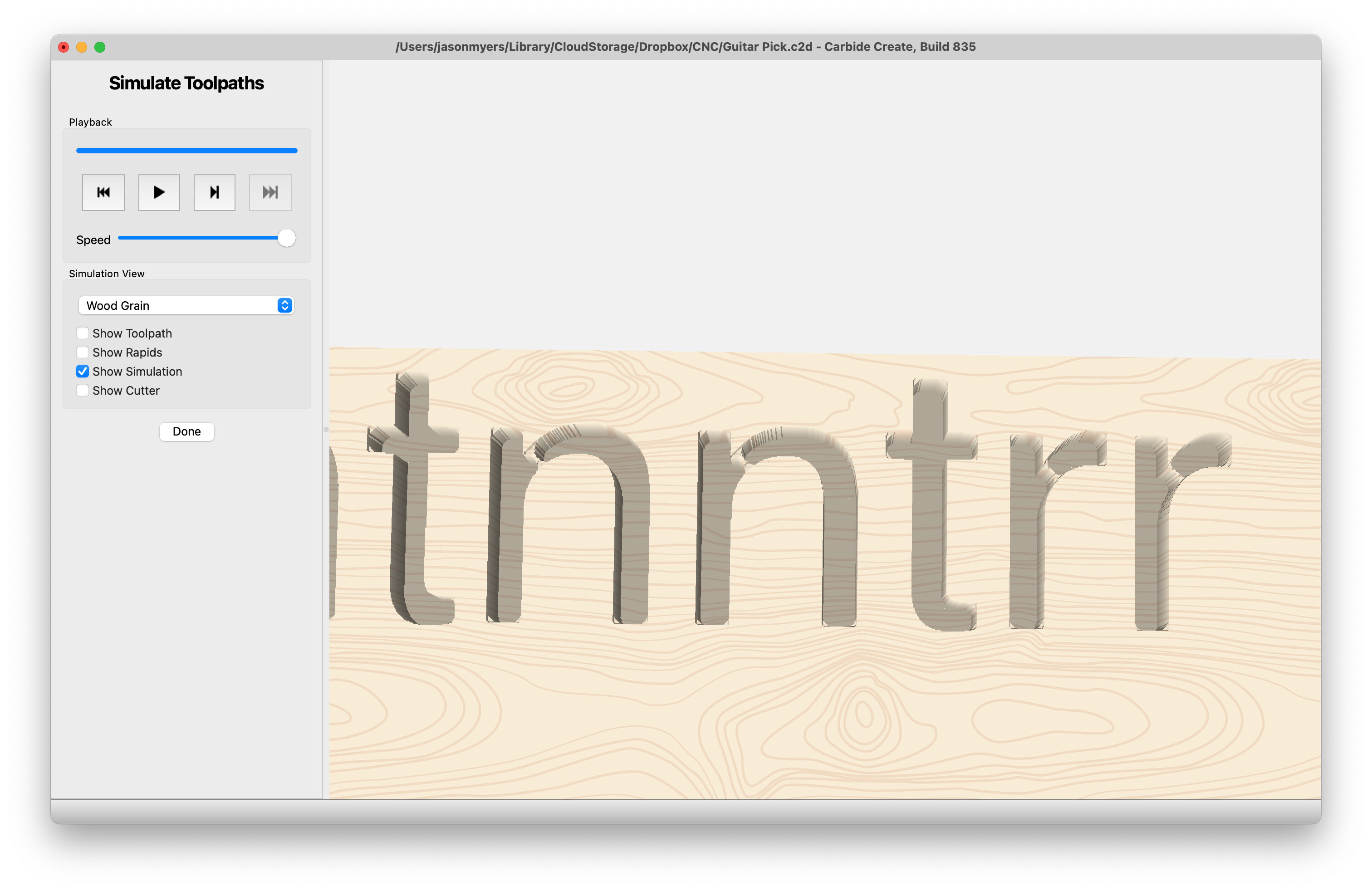
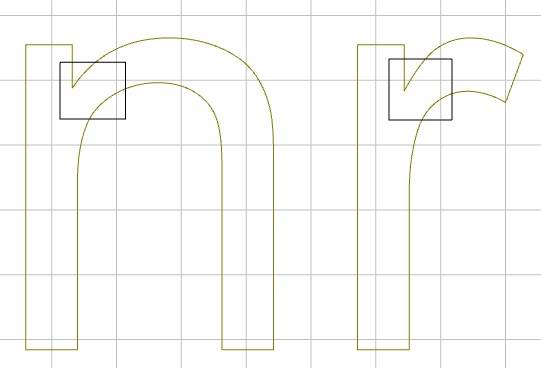
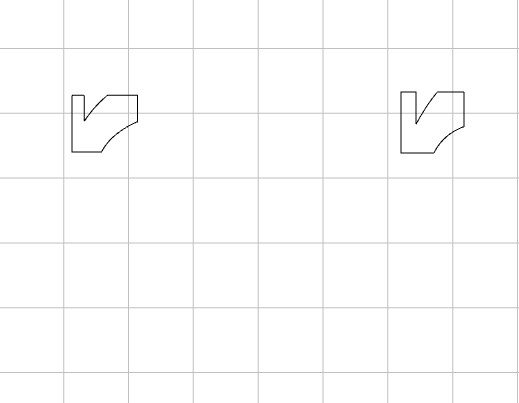
You can see here that the “n” and “r” have material left where the curve and straight sections meet. The corners aren’t square either.
I’m sure this same concept is applicable in many different contexts, but letter carving is one of the first that came up for me.
Edit as I write this - I found this thread: Should large pockets with details be cut with two bits? - #5 by mhotchin
It mentions the pocket + contour approach, but will that still yield rounded corners? Is an additional path with a vee bit necessary?
For context - I’m purely in the design phase - not using CC Pro (yet) - and trying to get a handle on how these things all work before jumping in and getting a machine and all the bells and whistles.
Thanks for your patience!