So, your experience indicate that 0.001 IPT works well with inserts cutting aluminum (6061 T6?). BW says in the link that “Modern tools for aluminum are often much sharper, and can take less chip load. In general, indexable tools are less sharp than endmills, so they need higher chip loads.” What does your cutter manufacturer recommend for speeds, feeds, and maximum speed for the cutters that you use?
Dangerous game you play when potential runnout is more than desired chipload…take that how you will.
In my experience, hundreds and hundreds of hours cutting aluminum…0.001 maximal chip thickness has never ever ever ever lead me wrong with any tool I’ve used.
The only cutters ive used that were meant for 30,000 rpm were Datron endmills. 0.005max, I was averaging 0.0035 actual.
Yonico makes endmills that are rated for 35,000 RPM. PreciseBits’ are rated for 100,000 RPM. What collet(s) do you use with your Makita? Have you measured their runout?
I regularly check TIR and usually adjust 0.125 and below. Using makita collets, Elaire, and cheap reducers. They are all usable and I try to have around 0.0005 tir although it’s not unusual to have up to 0.005-0.003 tir before adjustment.
Even on a 70watt spindle for t6-6061, 0.0008-0.001 minimums work very well.
What adjustments do you make to reduce runout? Did you get a custom Makita 3/8" collet from Elaire, this one from Makita,, or?
Check this out, I swear it works
I have the Makita 3/8s and haven’t had any issues with it except it requires a decent amount of force to clamp firmly due to its single split style. The Elaire metric set I have is very nice.
I spoke with Elaire and they do not offer a 3/8 collet for the Makita but as stated, you can get one from Makita which is what I’ve done. I have 1/16 and 3/32 collet reducers from Treeline USA but I have had little chance to use them yet.
That’s a great demonstration of the importance of using precision collets, especially with small endmills cutting metal!
That technique lets you dial in runnout even with the crappiest of collets. It’s pretty easy to have sub thou runnout with collet reducers.
Sure you could spend all your lunch money on precision collets or you could just learn how to make the things you have work, usually that’s better in the long run anyway lol.
The guy that made the video said that he was going to report back regarding how well his “adjustment” held up during use. Did he? Have you checked that?
I presume it should hold as long as the tool holder is in proper order.
It’s the same principle as tapping stock into concentricity on a lathe during setup.
Same technique chasing runout in a chuck for example, then you rely on it to hold throughout your cuts.
But the same effect may not be the same because the cutting force on the lathe stock is relatively constant whereas that on CNC endmills isn’t because of the flutes. What moves during the adjustments?
True. So a single flute we can agree on, but multiple flutes the question remains.
However, turning with a interrupted cut is not uncommon on a lathe (be it a cross hole or key slot, etc). I would suspect this to have a similar start stop effect as multiple flutes and again is really a non issue when done properly.
As long as you don’t overexert the toolholder/workholder then all is well. Which should be common practice but then again it can be trial and error when employing new methods.
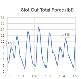
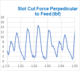
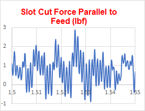
As shown below, forces on an endmills look like those of a high speed impact drivers. Chart X axis is time in seconds and Y axis is total force in pounds. (Whiteside RU2100 2 flute 1/4" endmill cutting 1/4" by 1/4" slot in yellow poplar at 15765 RPM and 160 IPM on S3 XXL with Dewalt DWP611 router.)

Is this calculated or measured force?
It’s calculated from measurements of the force perpendicular (+X) to the feed direction and the force in the feed direction (+Y).


What program do you use to calculate this? I’ve been curious about what kind of forces the Shapeoko sees and can handle during milling.
I used Microsoft Excel to do the calculations. That was trivial. Making the necessary force measurements was far from trivial. Calculating force from measured router/spindle input power increase and RPM when cutting is a lot easier!
That’s interesting. So you tracked power to the spindle over time and back calculated to cutting forces?
I started out using a jig that used load cells and instrumentation amplifiers with a data acquisition system and a computer to measure and log X and Y axis workpiece forces. Excel was then used to analyze the data (like in the above charts). After that I started using a power meter to monitor the router input power increase when cutting. Total cutting force can then be approximated from the power increase, router speed, and endmill diameter. The power meter provides a near real time (0.5 second response time) reading of average (RMS) cutting force (which is proportional to router input power).