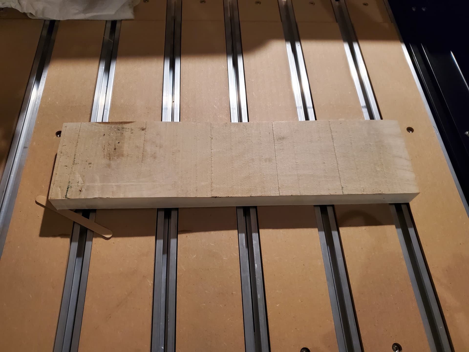
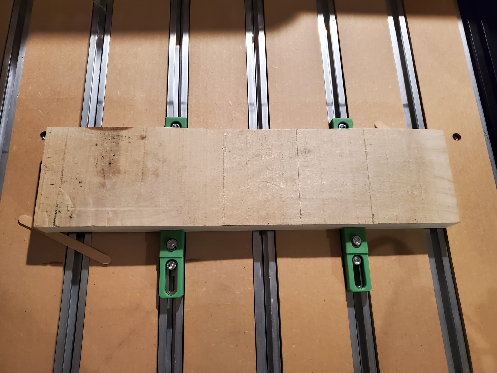
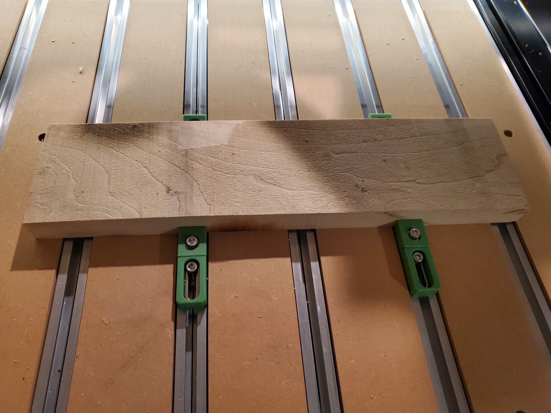
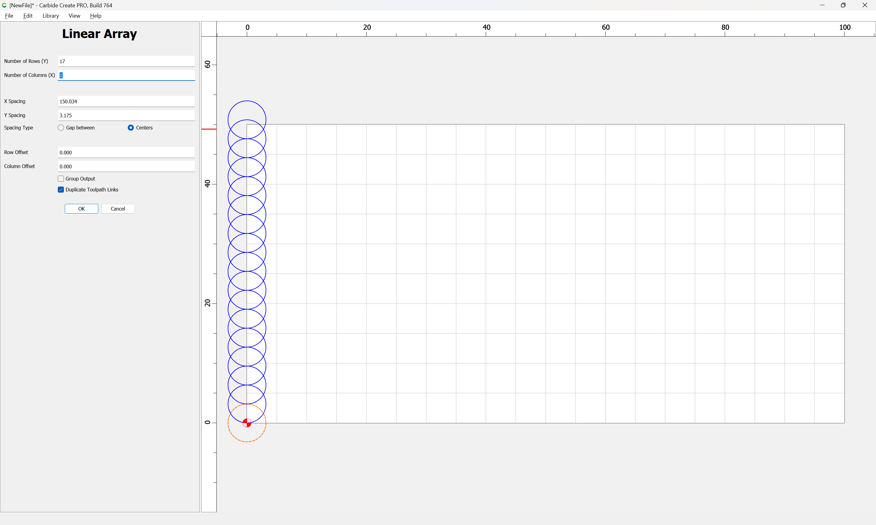
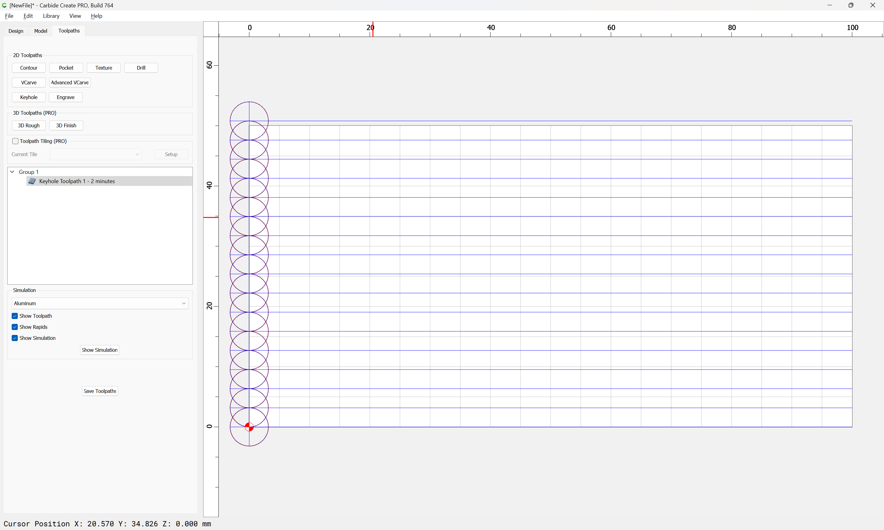
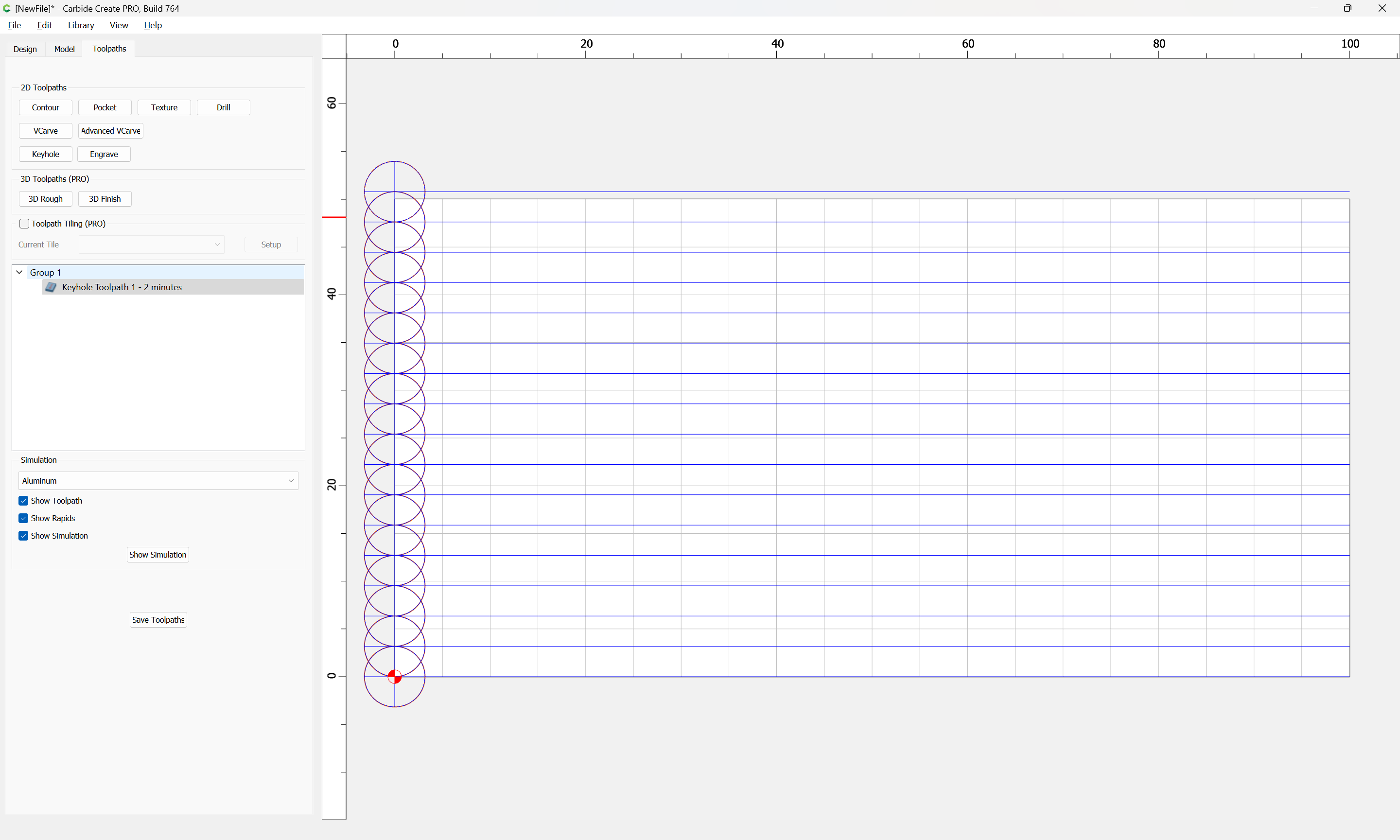
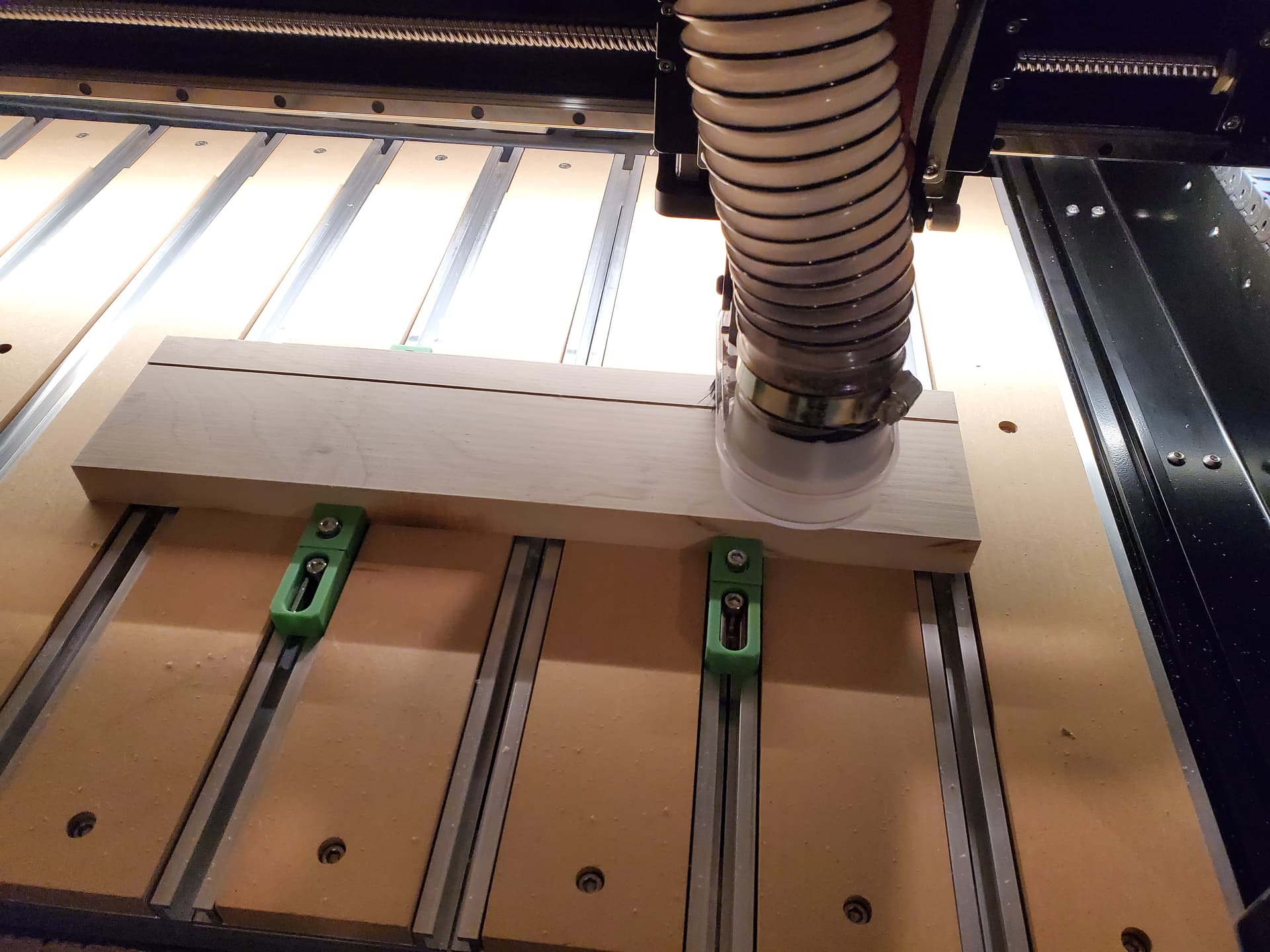
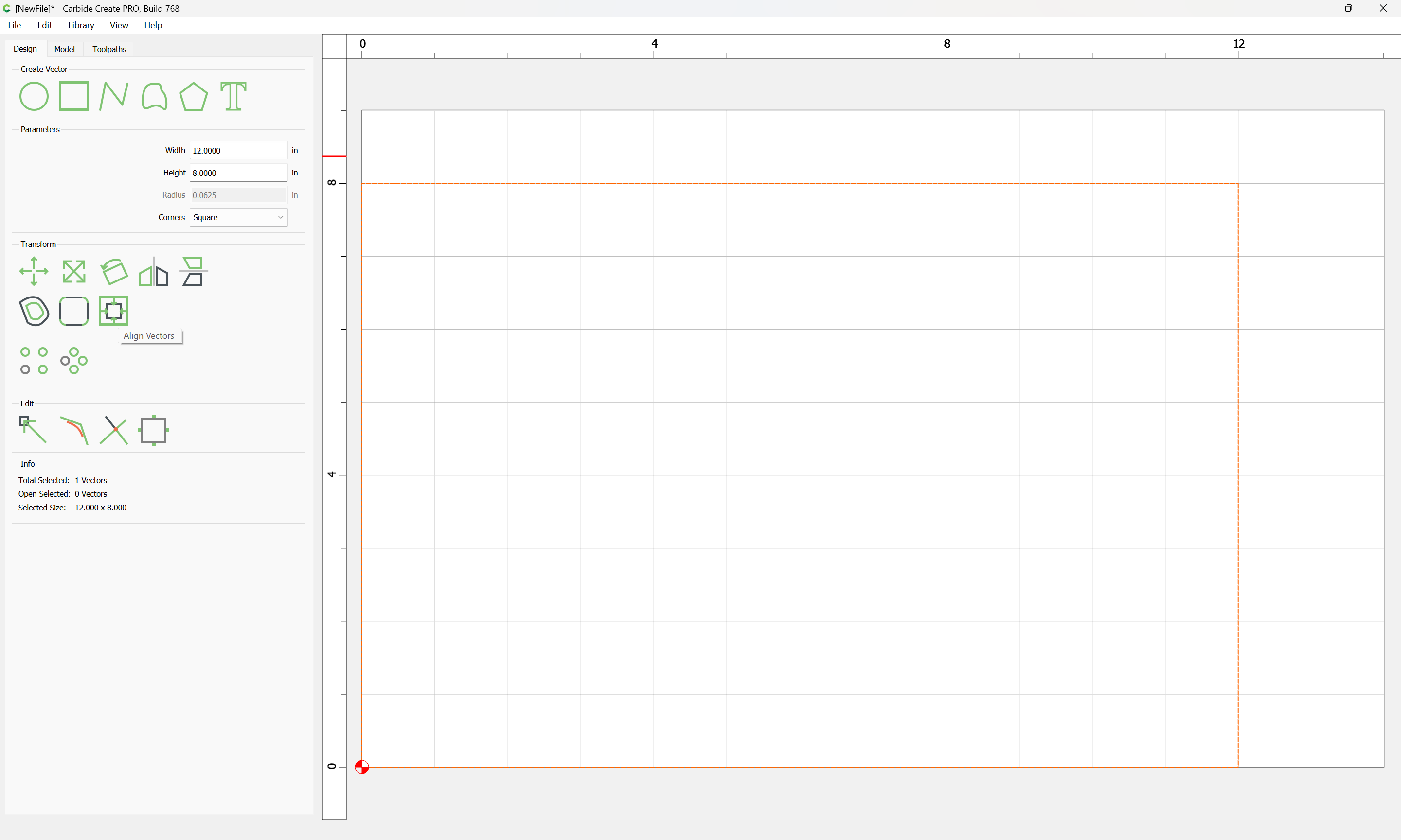
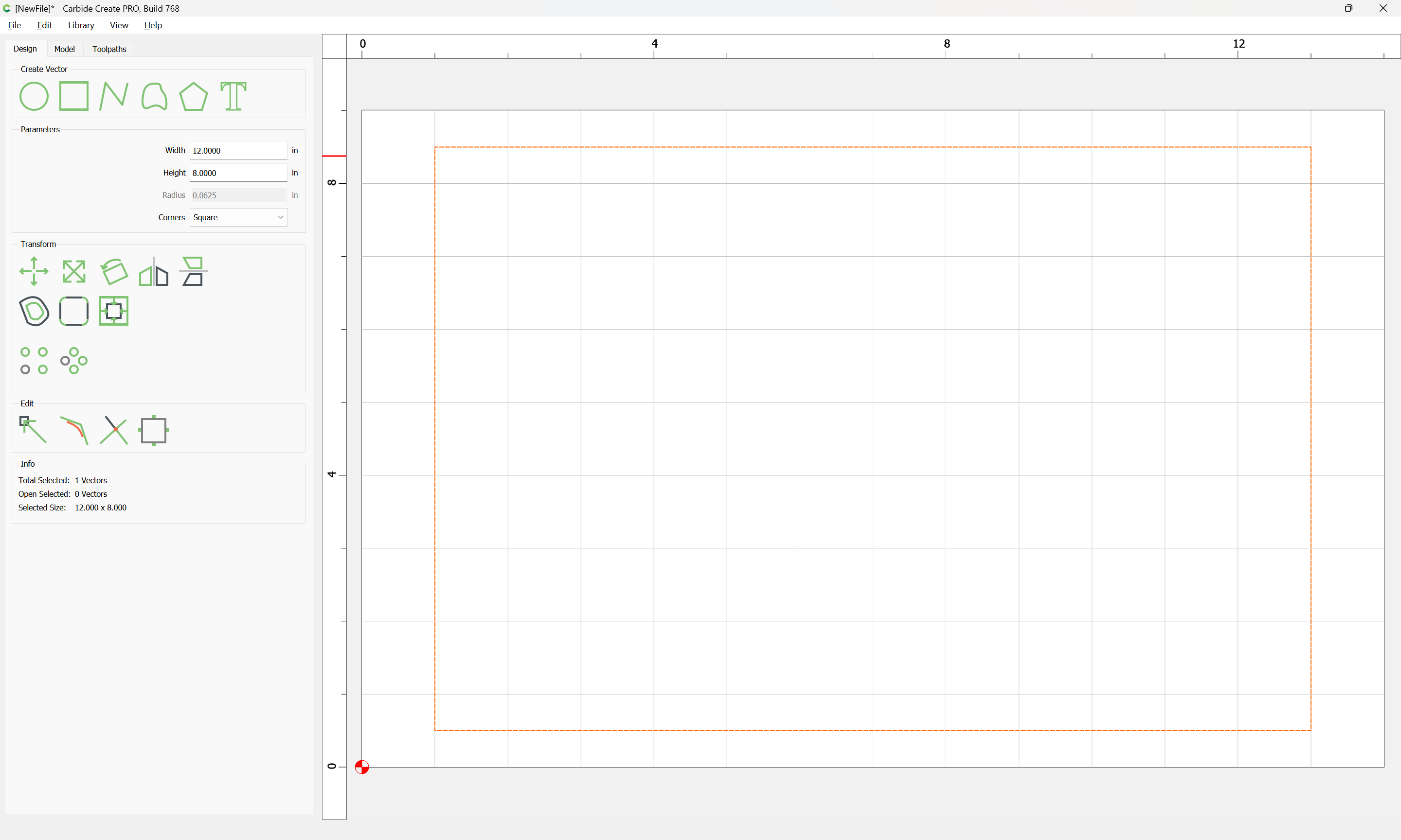
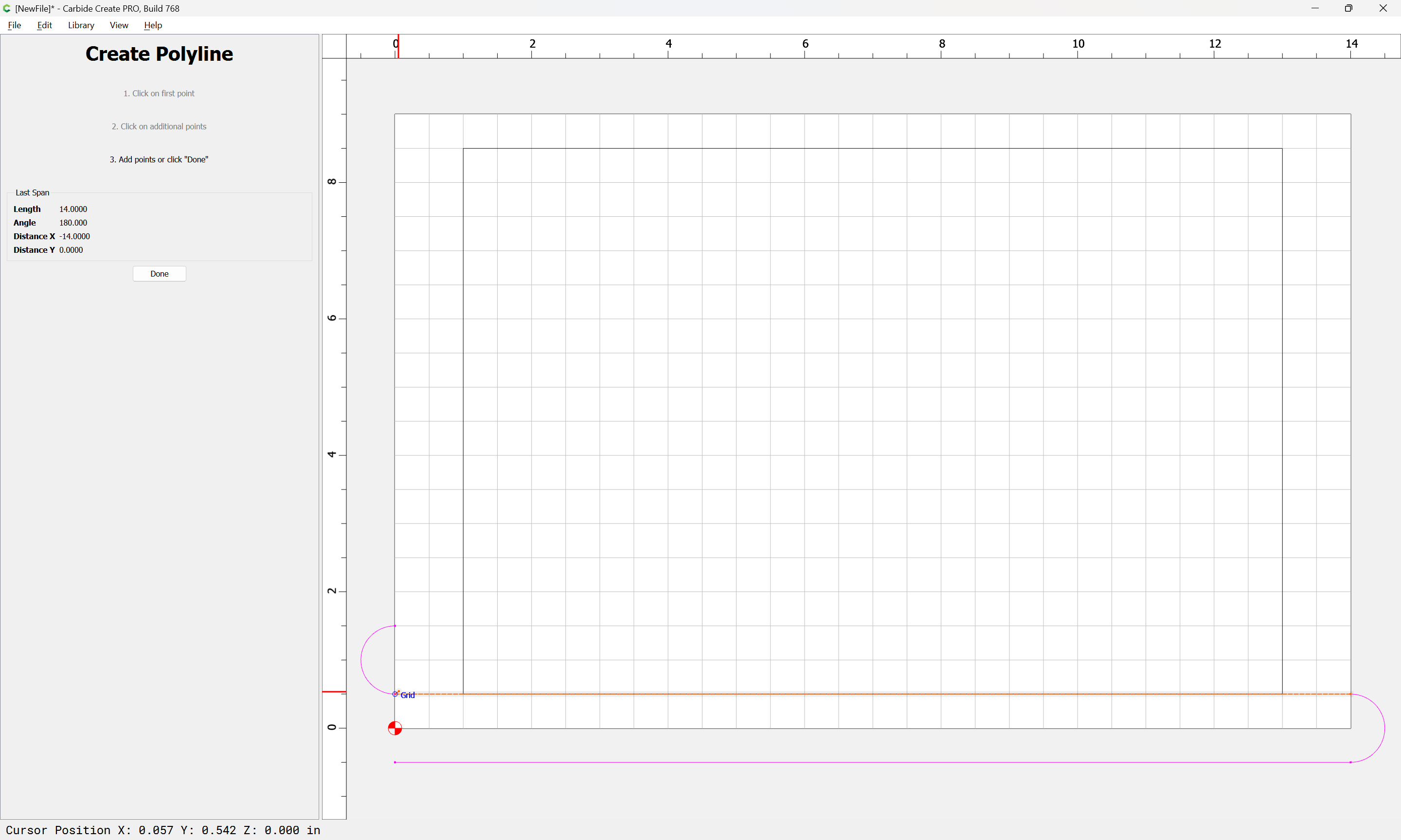
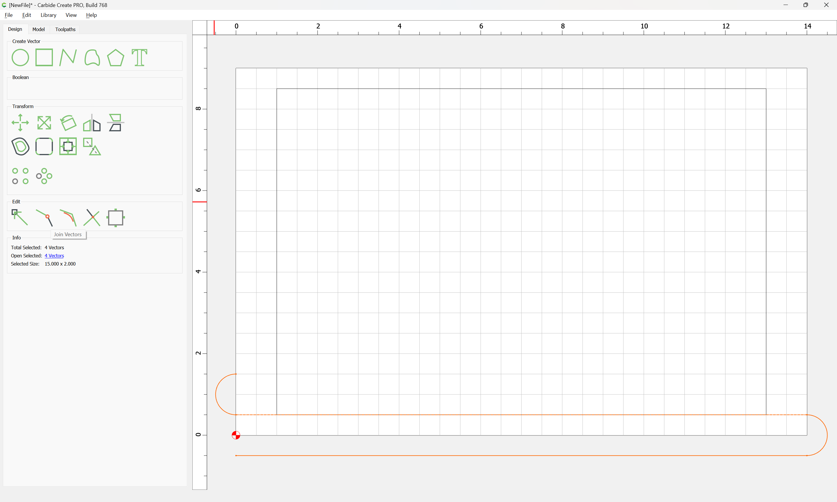
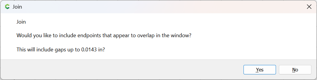
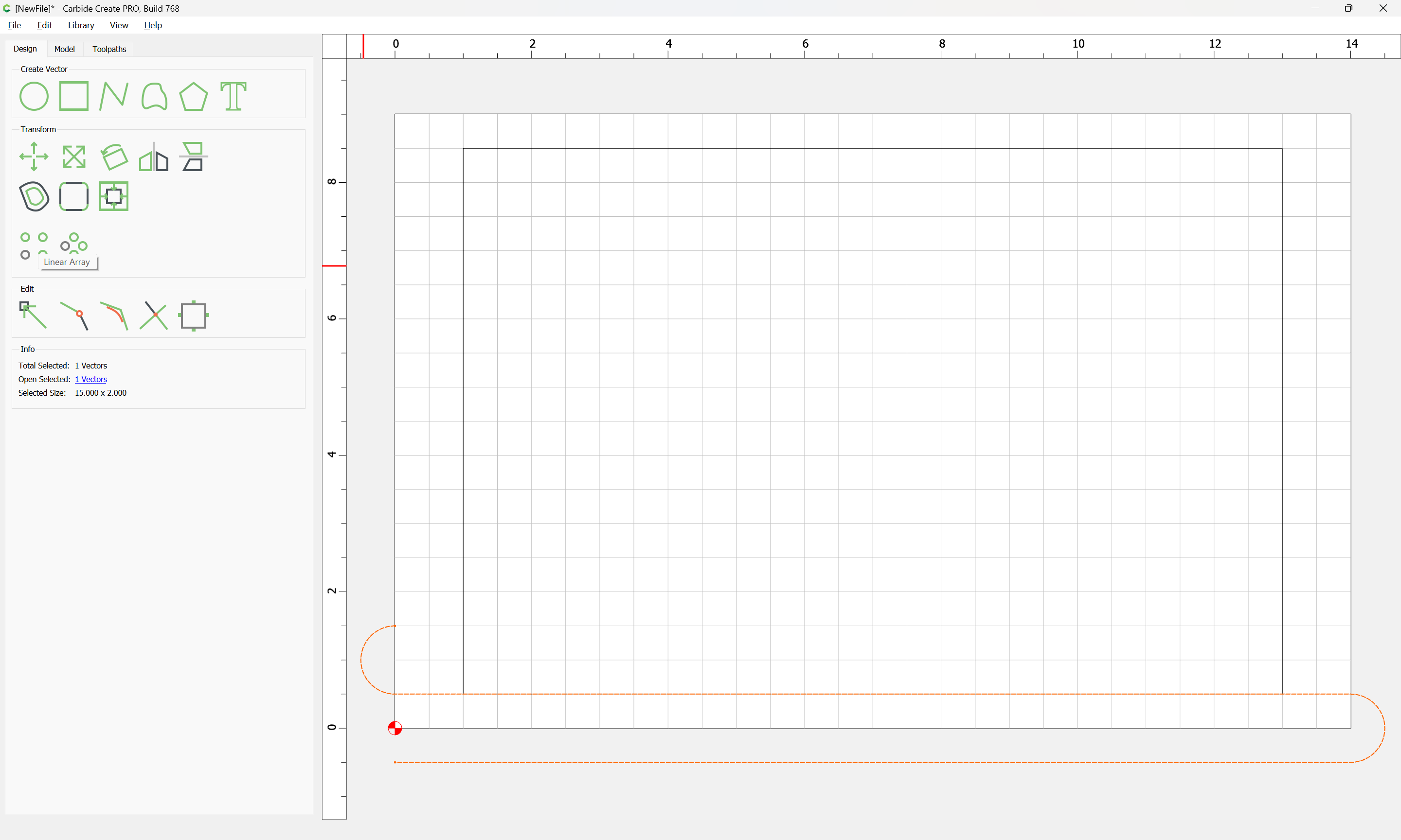
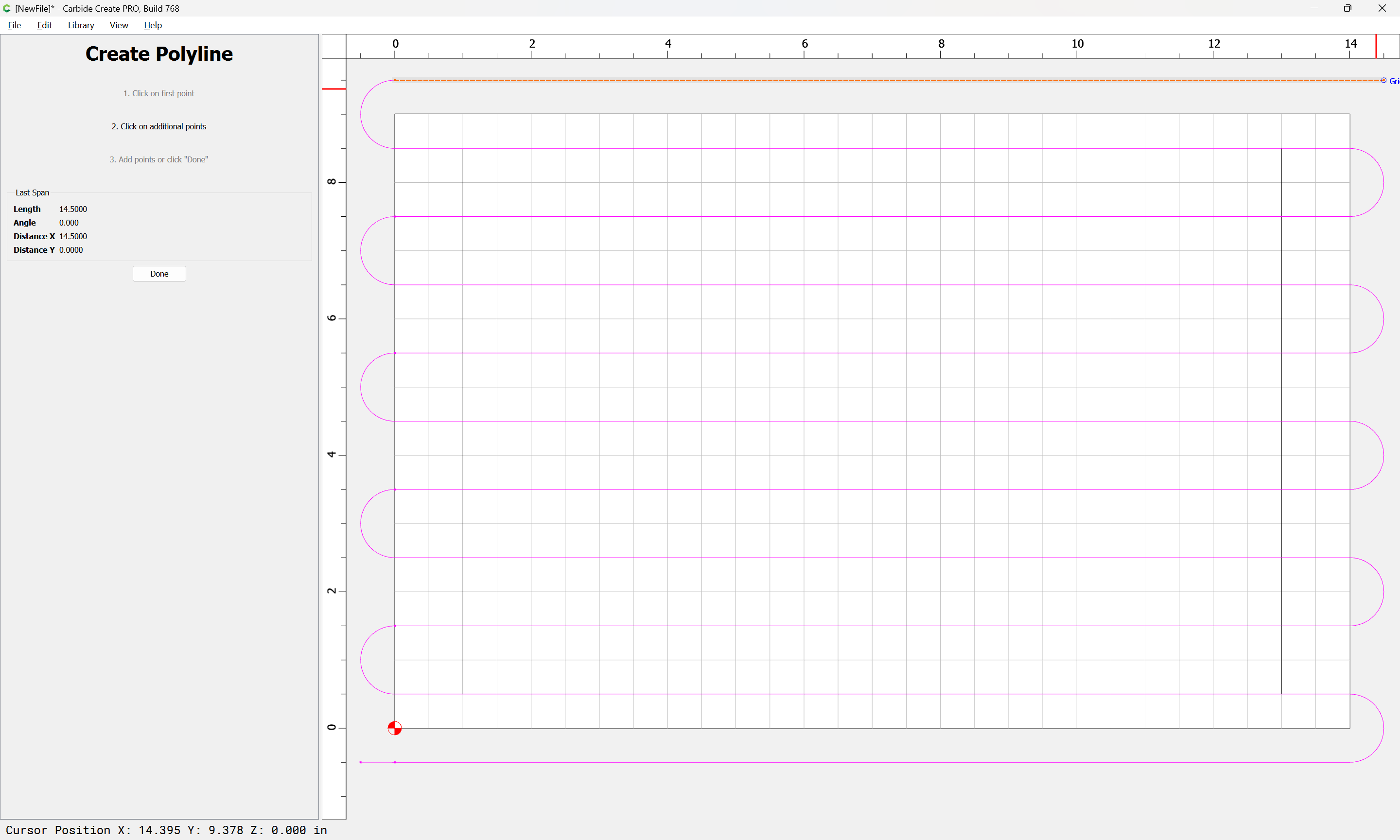
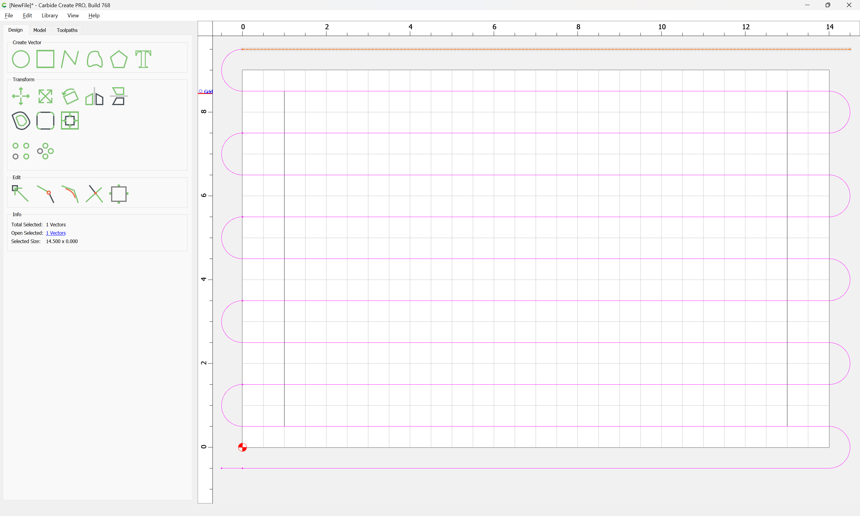
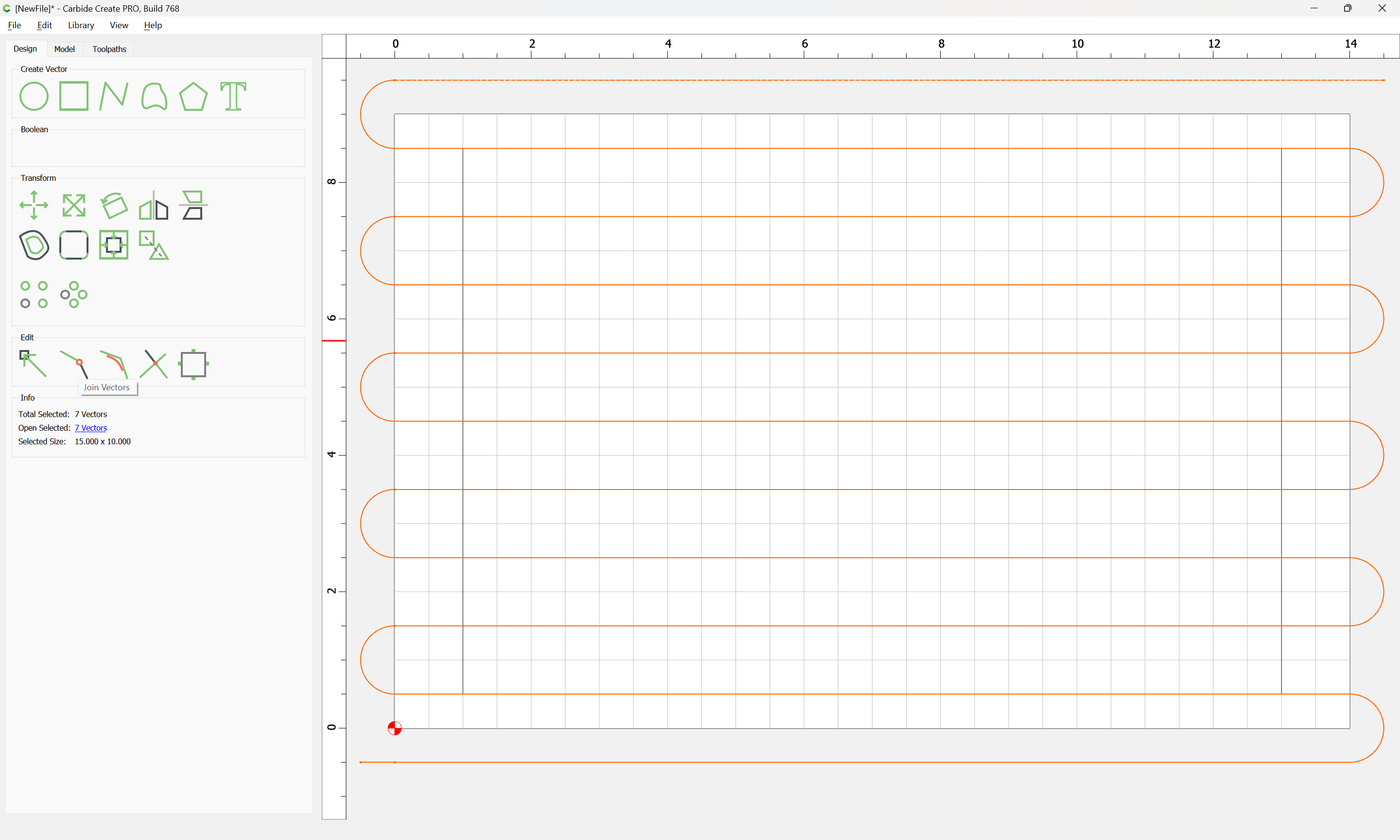
one sets it on the machine, and if need be, adds shims where/as needed to make it as level as possible. and clamp in such a way that the entire top may be surfaced off
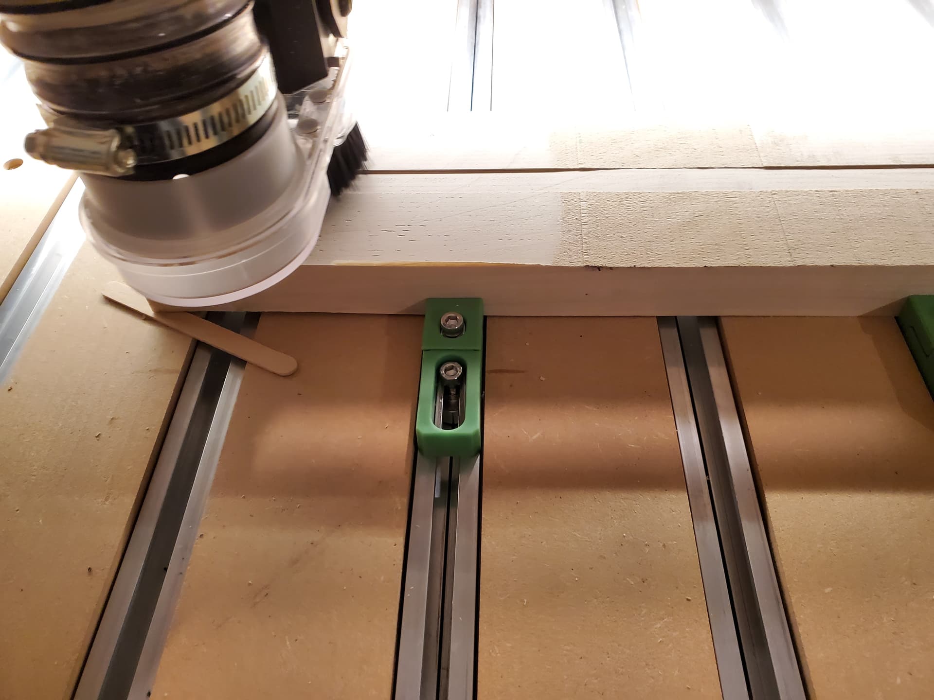
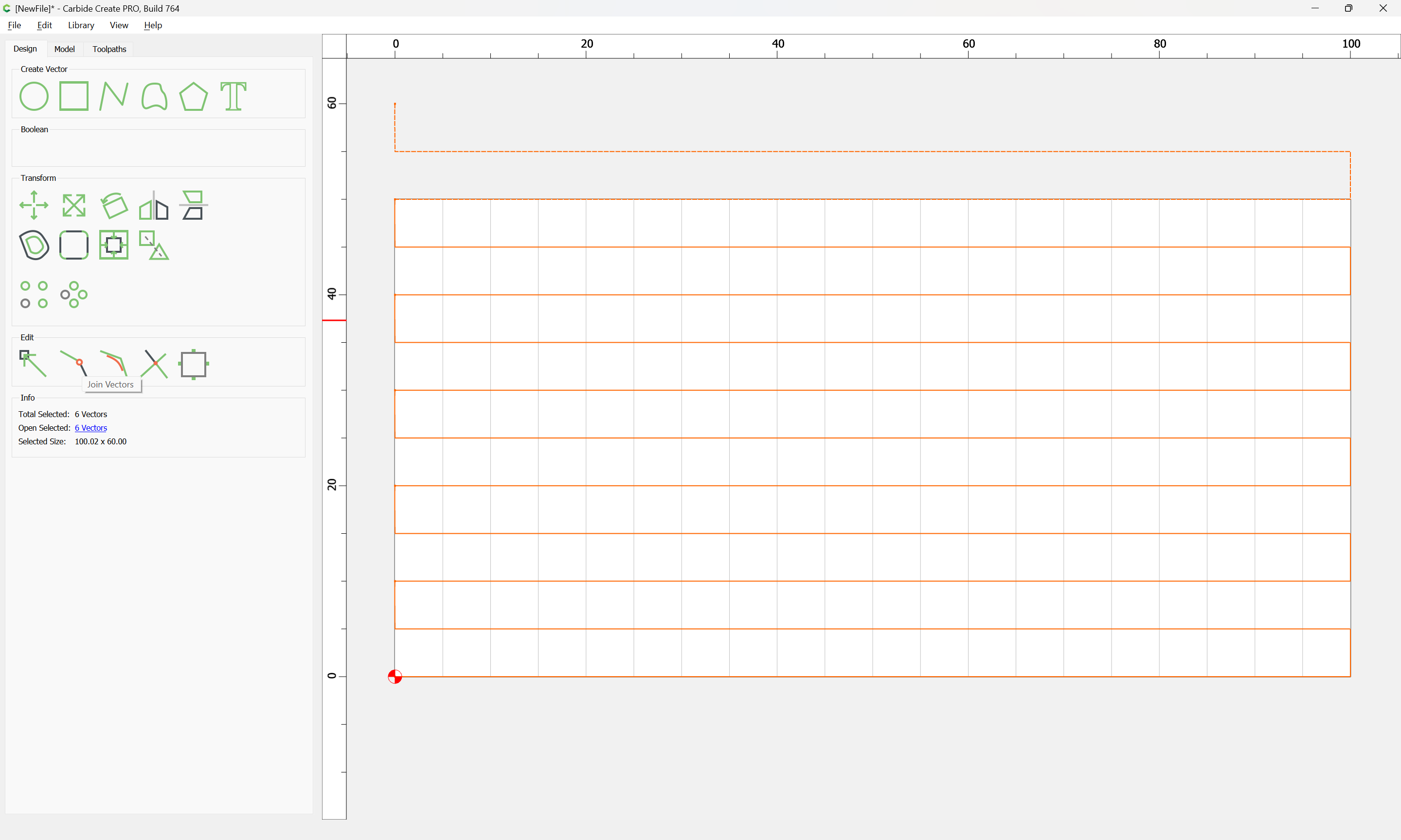
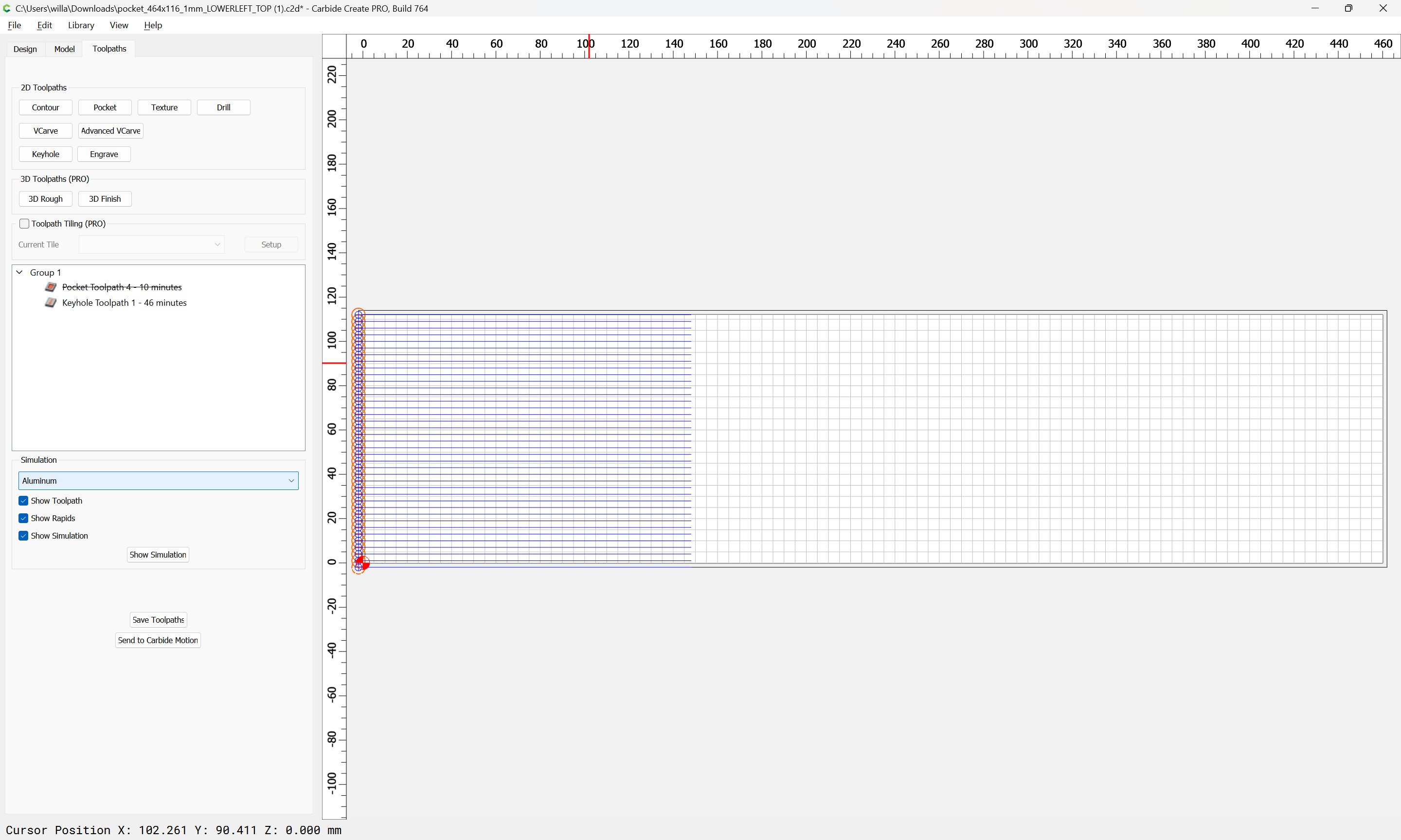
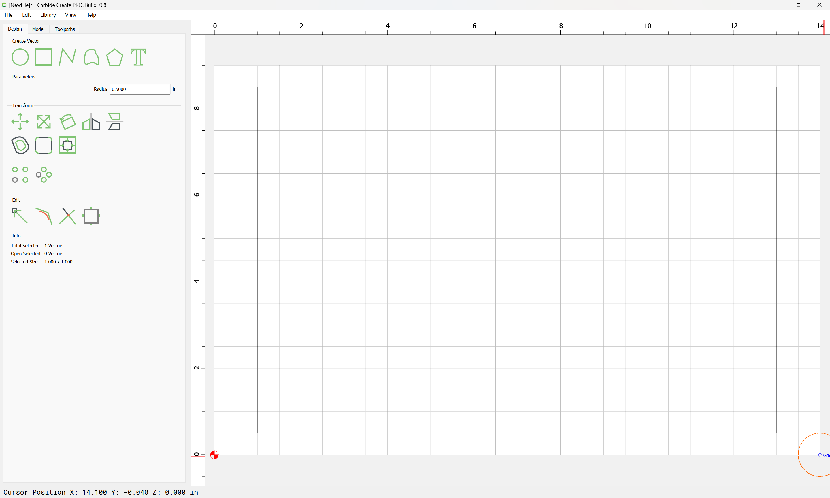
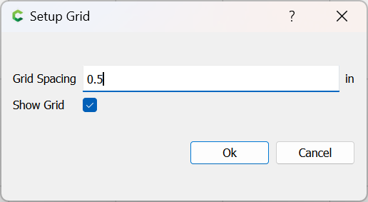
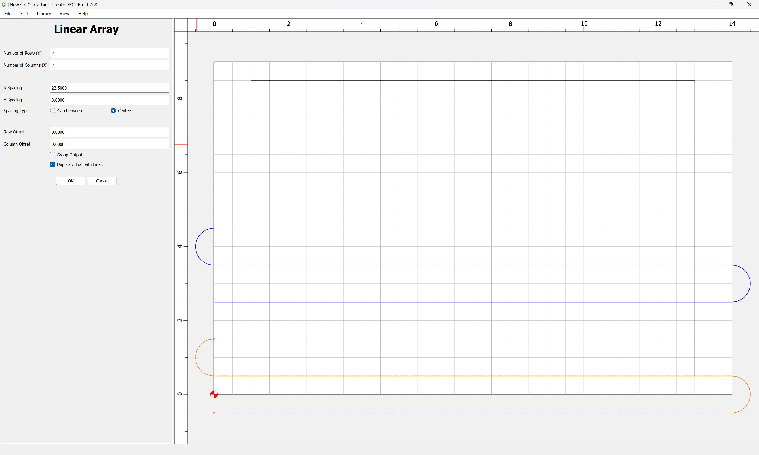
if a repeat is necessary, jog down to zero, then down by the cut depth of the file (1mm) set zero there and repeat — the zero may be adjusted as need be until one arrives at:
Just had to do this with the chunk of red cedar I used in my recent topographical carving. Would have been nice of you to jump in your time machine, @WillAdams and post this about two weeks ago, lol, probably would have saved me the time I spent pondering best way to approach this. I can vouch for this procedure, exactly same solution I came up with.
I ended up doing this with a piece of Osange Orange I used for a charcuterie board. It came planed but not flattened properly. The piece was too wide for my planer so just put it on my Shapeoko, wedged it and ran a flattening pass. Worked like a charm and no more wobble in the board!
I buy rough sawn oak by the skid load and have many uneven pieces all the time. I have a wood planer that I can send many of the pieces thru at any given time. But width limitations become my issue. I bought a 1" surfacing mill bit but have not found a good way to make a surfacing program, because I really haven’t thought about it much and tried my hand in it, but it would be nice to have a few different surfacing programs for many different size boards needing leveled.
Hell, would even love to be able to surface big plywood pieces that are very uneven that I would like to use. I don’t always like to use plywood because of the cleanup that has to take place afterwards. I know the Shapeoko 5 Pro can surface boards, but I just haven’t looked into it yet.
Thank you. This will be of some big help. Not liking some of my projects that have just a little bit of a difference in the wrong places of the wood that makes it unable to be just shimmed. Looking forward to being able to surface some of these oak planks and then making my projects from them.
Thank you for the assist. I had a project come up that was needing a bigger piece then my planer could handle. I had already spent too many hours designing the project and to spend more time looking into top surfacing the material was too much. So, I for go the surfacing and just used my belt sander on the piece to get it relatively flat and then palm sander to smooth. The project went well on the first cut thru other then the minor changes I needed to do on the design.
Then the second cut thru went worse because the plywood I used had a massive void in two places in the sub-layers. Once I started cutting into the voids I realized that they weren’t going to look good and I was right after the machine was done cutting. I was hoping the voids would come together with the whole design, but the voids even extended under areas that I had cut, which made that area of the cut weak.
From now on, after dealing with this kind of material disappointment, I will begin gluing up planks for wider jobs with hardwoods instead of the plywood that are mostly made of pine.