I have wanted to do another speaker project for a while since my last one turned out surprisingly well!
This time though I want to go big and make something crazy with my Shapeoko and this topic will serve as my progress write up for the project. When it is all completed I will make a video too
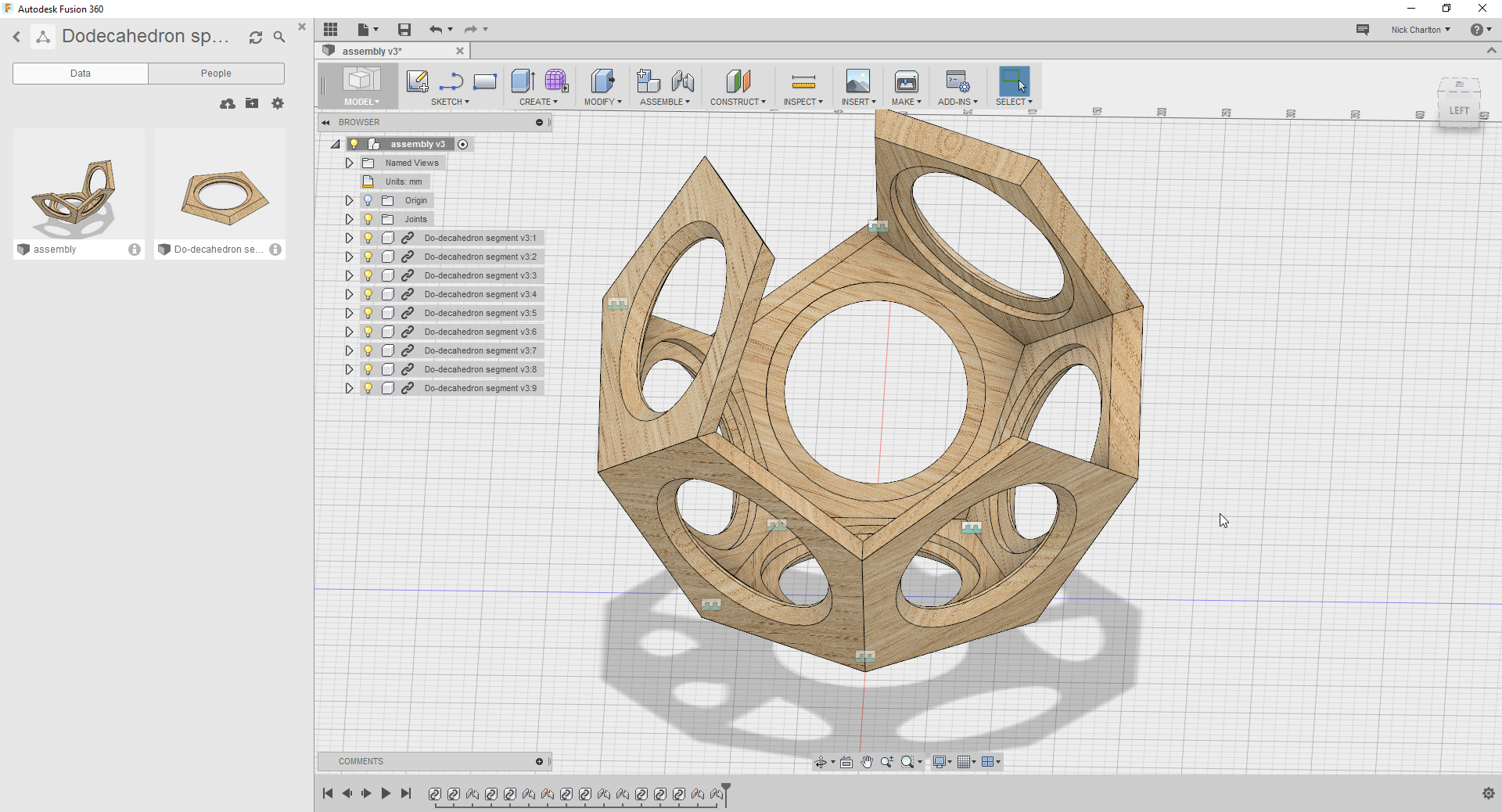
All projects start with a design and since I know that I want to make a dodecahedron I didn’t feel the need to do sketches but simply constructed the regular geometric shape in Fusion 360. I normally use Autodesk Inventor but I have heard some good things about the integration of Fusion and Autodesk Cloud Render which I use regularly so why not give it a try!
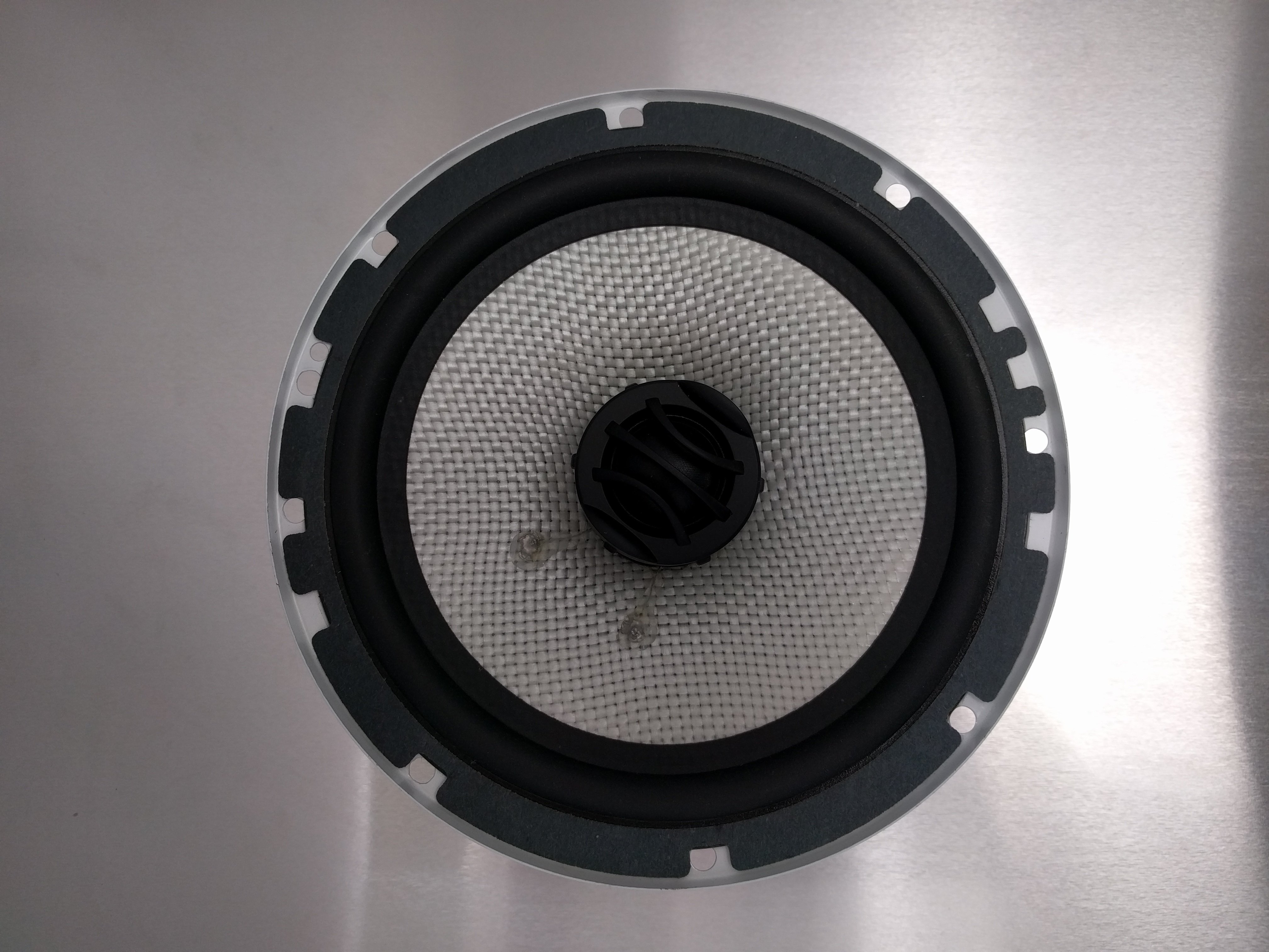
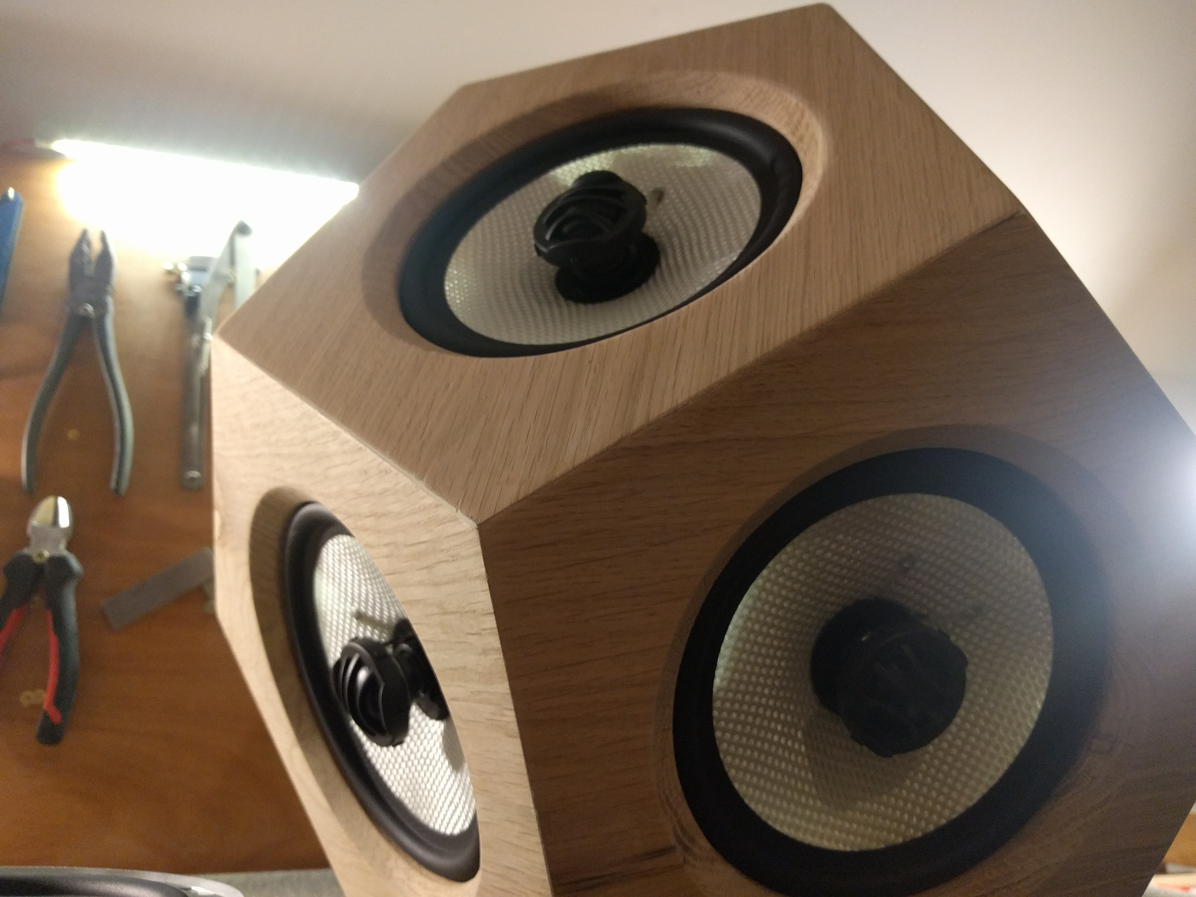
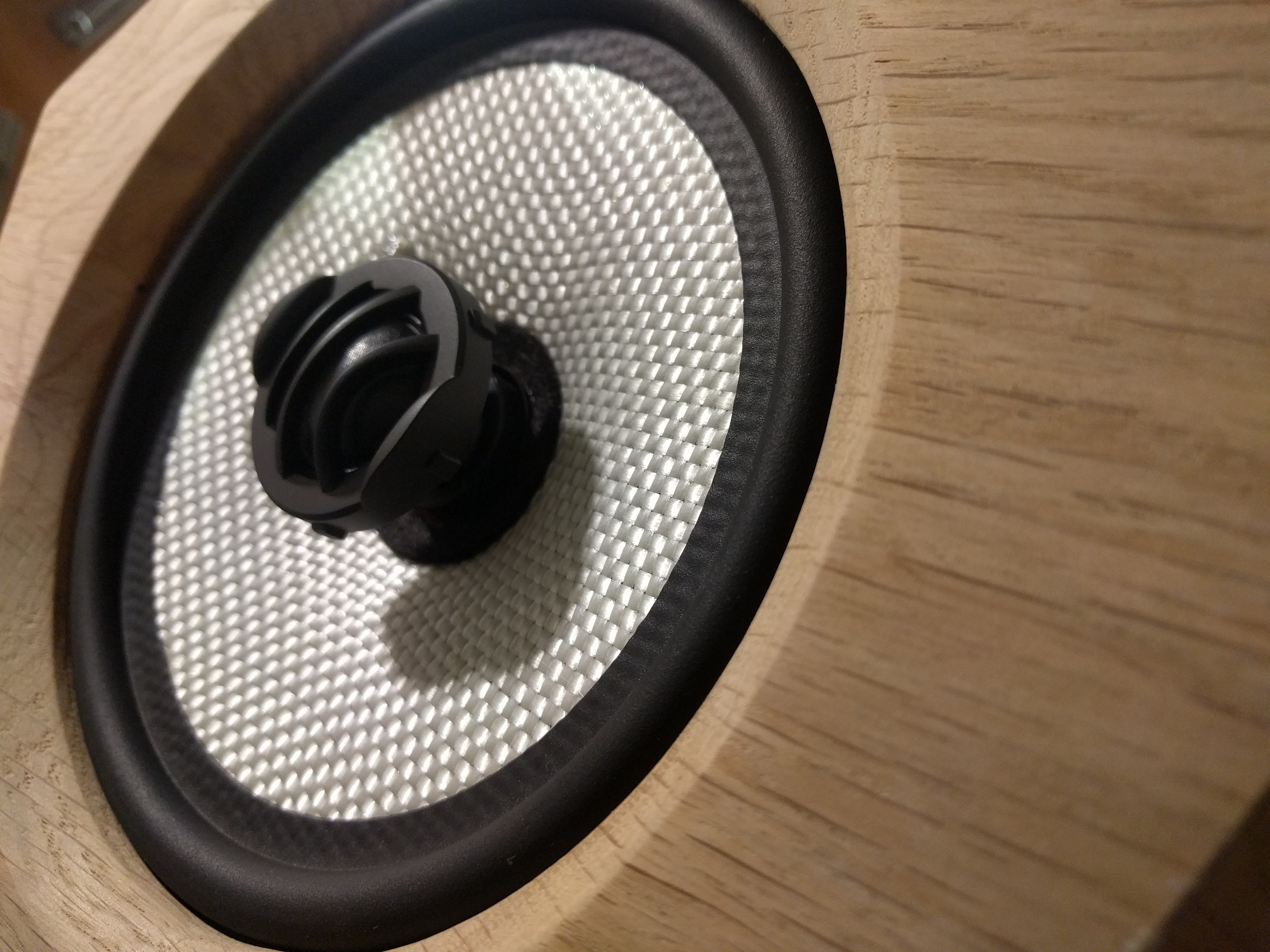
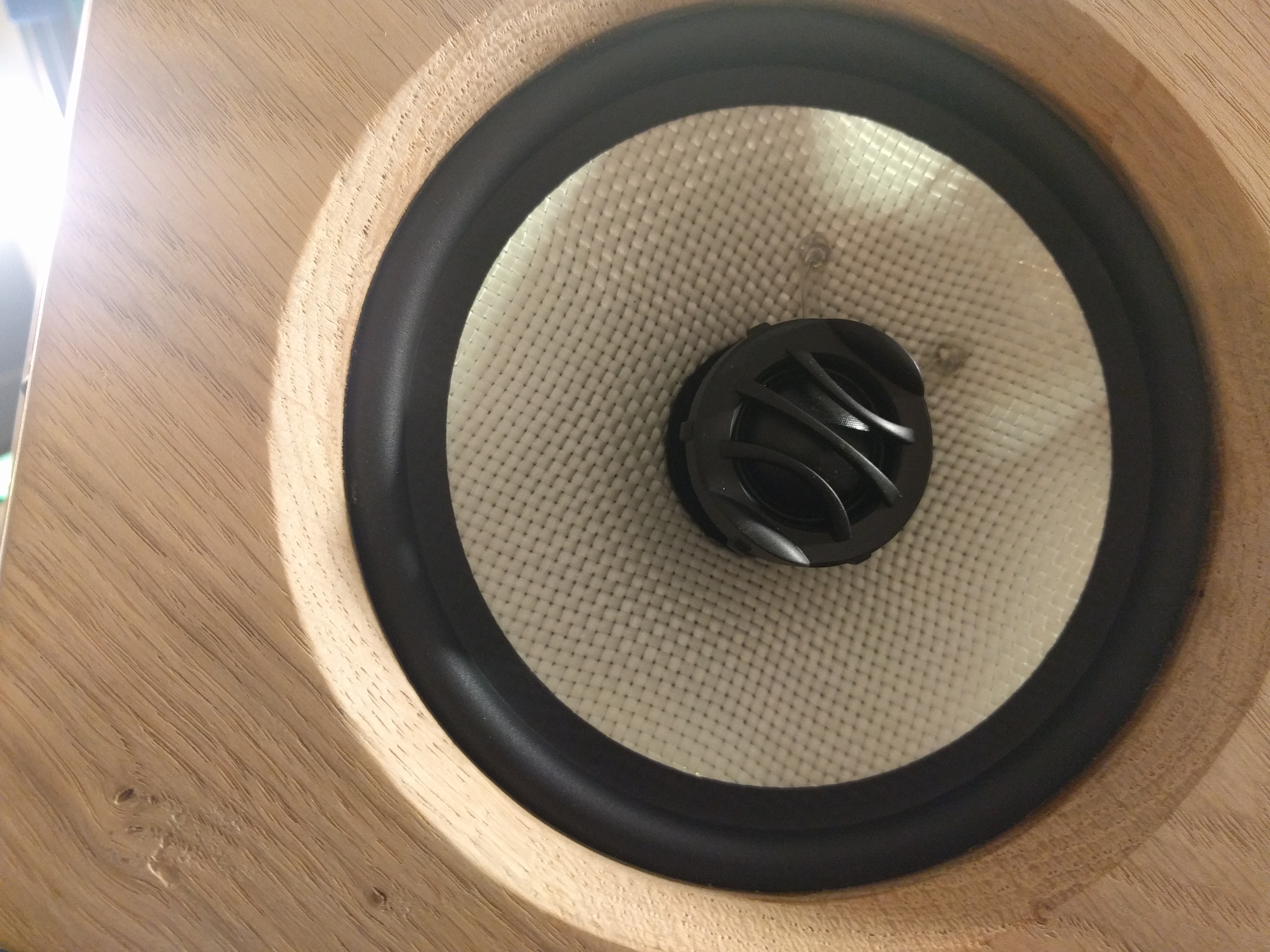
The speakers I am going to use are some fairly cheap ones from amazon which have a built in tweeter so no need to have to source them separately and organize them around the shape.
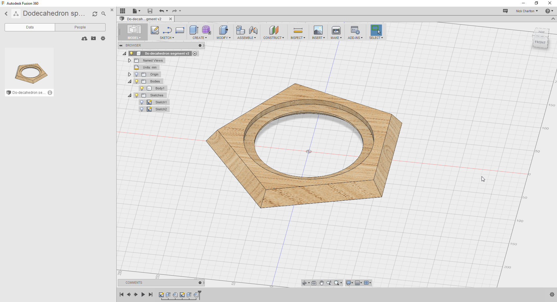
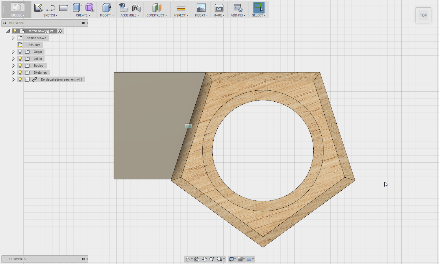
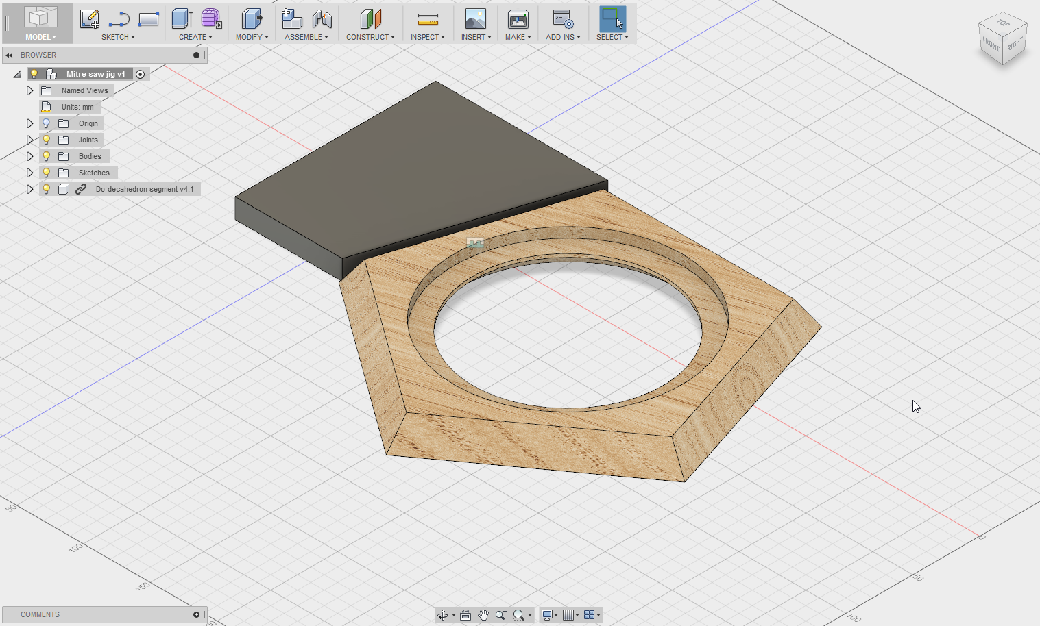
I started out with a regular pentagon in Fusion 360 and made it the thickness of my material (20mm White Oak), pocketed a central hole that is just bigger than the main part of the speaker.
Next I cut the chamfers that allow the pieces to fit seamlessly together (in theory). For a dodecahedron the dihedral angle is 116.56 degrees which means each segment must have a chamfer of around 56.28 degrees. I still haven’t decided whether I am going to 3d machine this or cut it on my compound miter saw… I also added an oak appearance to the model at this point. It looks so much better in Fusion vs Inventor!
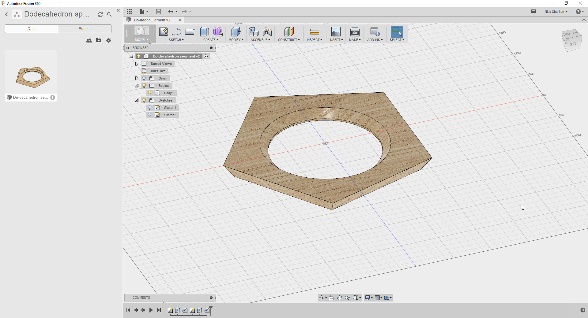
Chamfered the edge around where the speaker will show for aesthetics. This won’t be CNC’d, I will use a router instead.
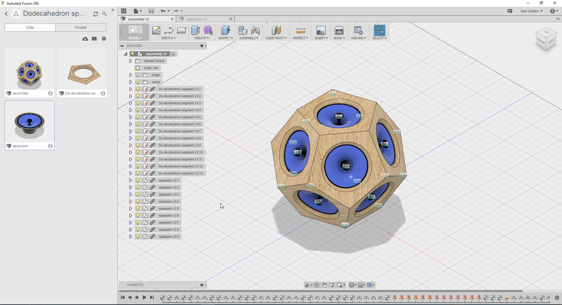
Added some speakers cones I got from Grabcad.com. Couldn’t find a model for the ones I have but it would have taken along time to model them from scratch so this will give the general idea of the speaker and will allow me to do a nice rendering!
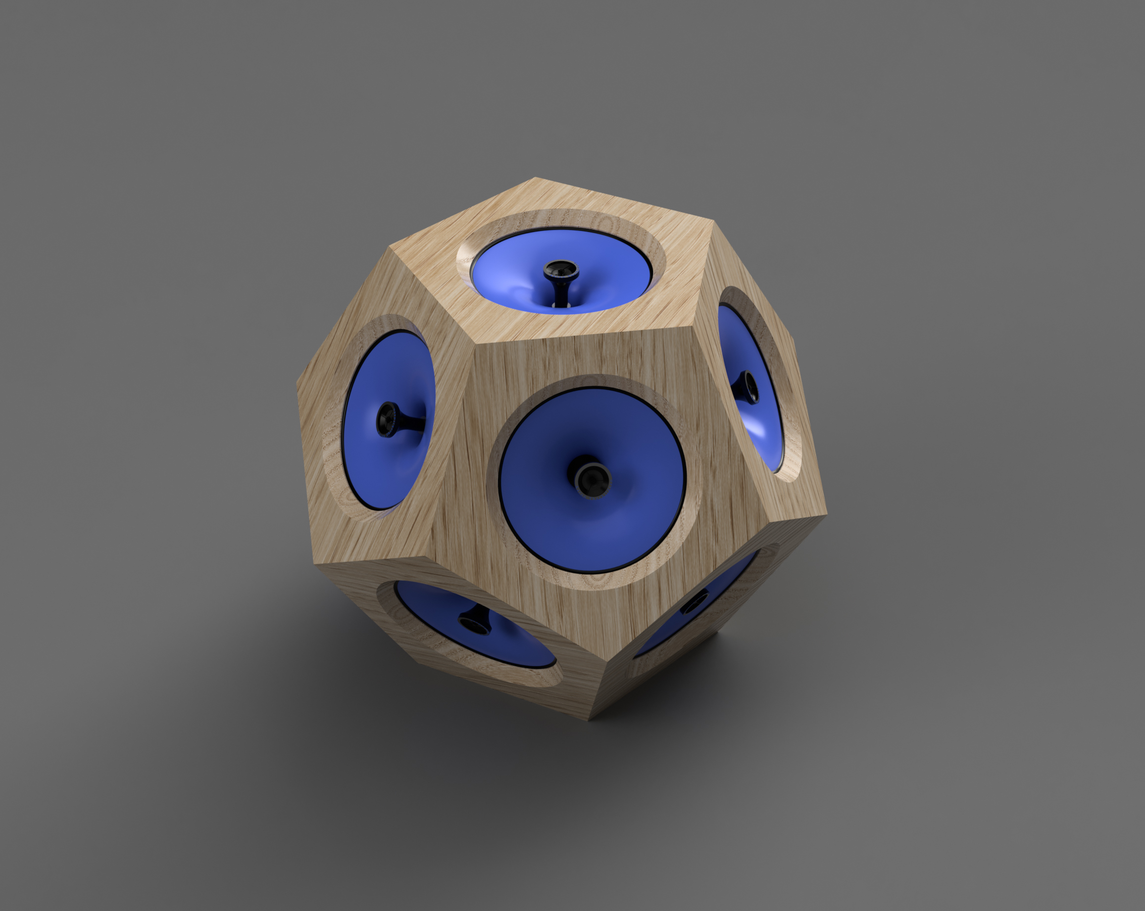
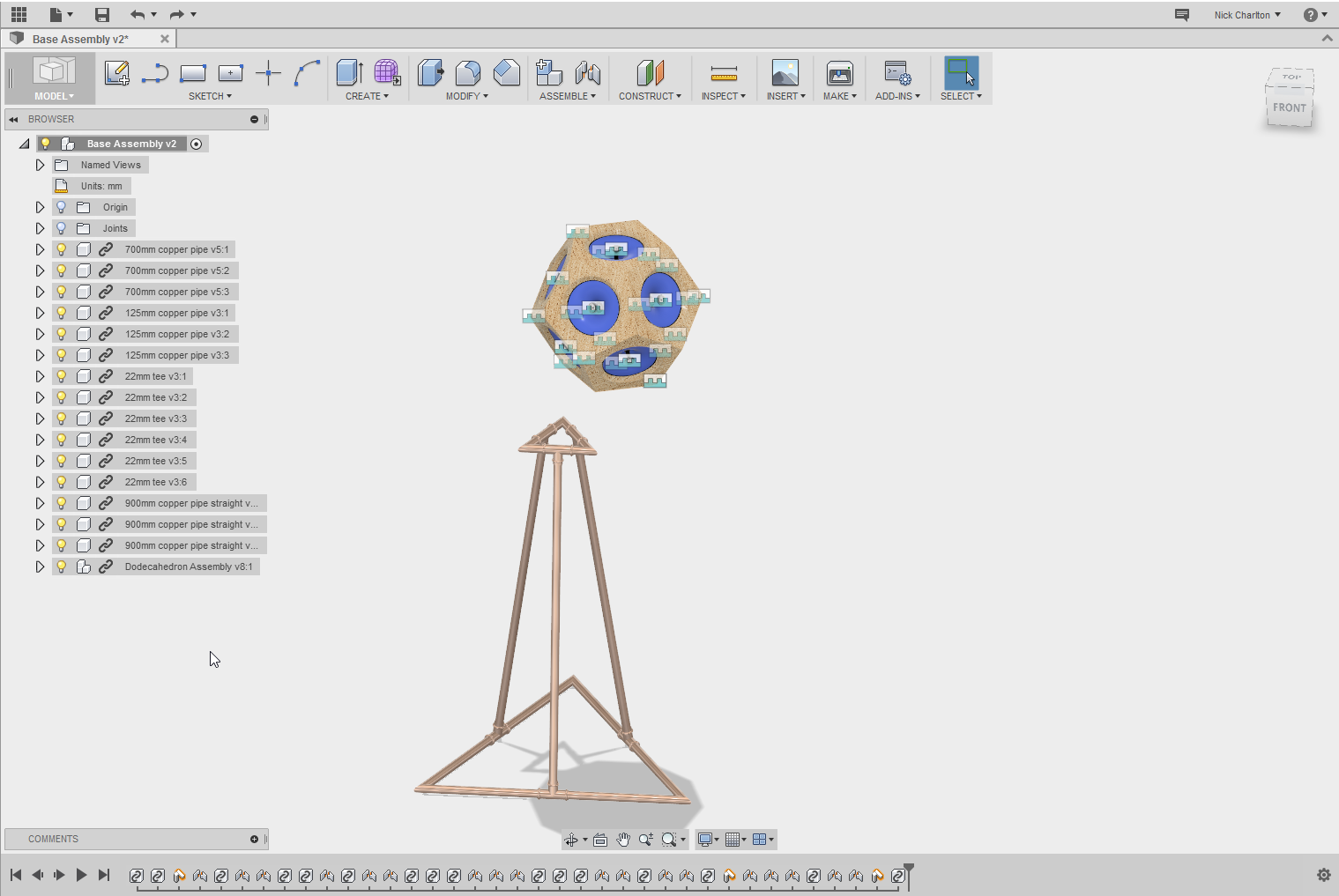
Here is a quick render that I did. I am not sure about the stand or what orientation the speaker will be. I envisage a polished copper tube stand with the dodecahedron sitting with a point pointing up, but i’ll cross that bridge when I come to it!
Step 2 is getting the material sorted and protyping
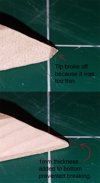
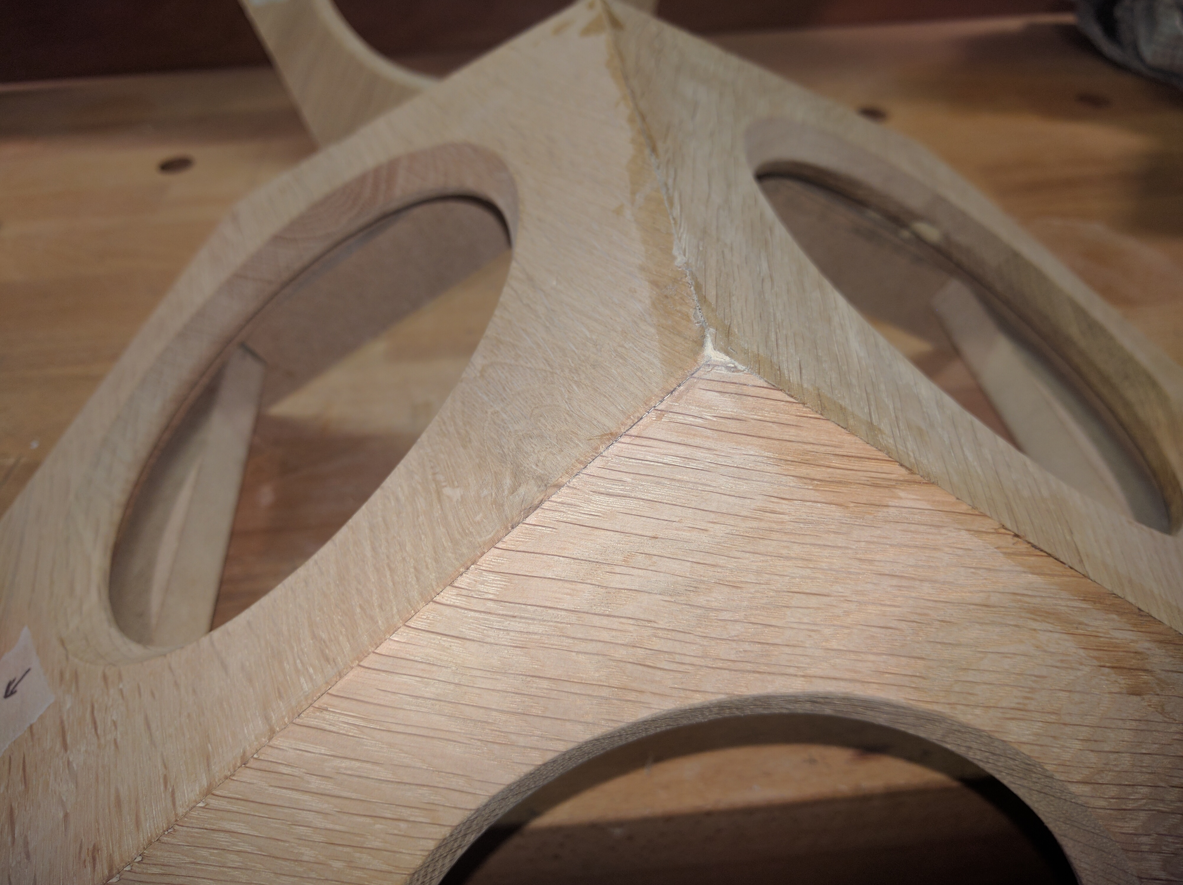
I’ve made a few polyhedrons with my Shapeoko. I can tell you right away where the grain is cutting across the very tip of the corner, that those might break off during milling or handling and assembly.
My recommendation would be to add some thickness to the bottom (outside face) of the polygons to reinforce the tips, and then sand the faces down after assembly.
Here’s an extreme example of what I’m talking about with some 5-pointed stars that I recently milled. Your corners obviously aren’t as sharp as these, so it will be less off a problem. But doing this will help you achieve sharp edges on the final product.
Also, to ease assembly, I’d suggest creating some interlocking notching to keep the pieces from sliding around on you during glue-up.
In order to do this well with thin plywood sheet stock, you may just want to route in slots that you could stick square dowel pins in that could engage both pieces, if you don’t want to do an interlocking digit pattern (to keep a clean straight outside edge).
Also a good move—but that won’t add to overall structural integrity of the end product, whereas moving from butt-joints to something that gives you more physical interlock will
I always try to make everything I make a bit drop-resistant, on the expectation that I will butter-fingers it at some point.
Blind joint notches and pegs will also help line up the pieces, but you have to be careful in thinking about assembly. in a simple box, 90 degrees are all easy to do, but you will need to be careful about how you put in your last piece(s). If you do a glue-up all at once and don’t use CA glue you should be ok.
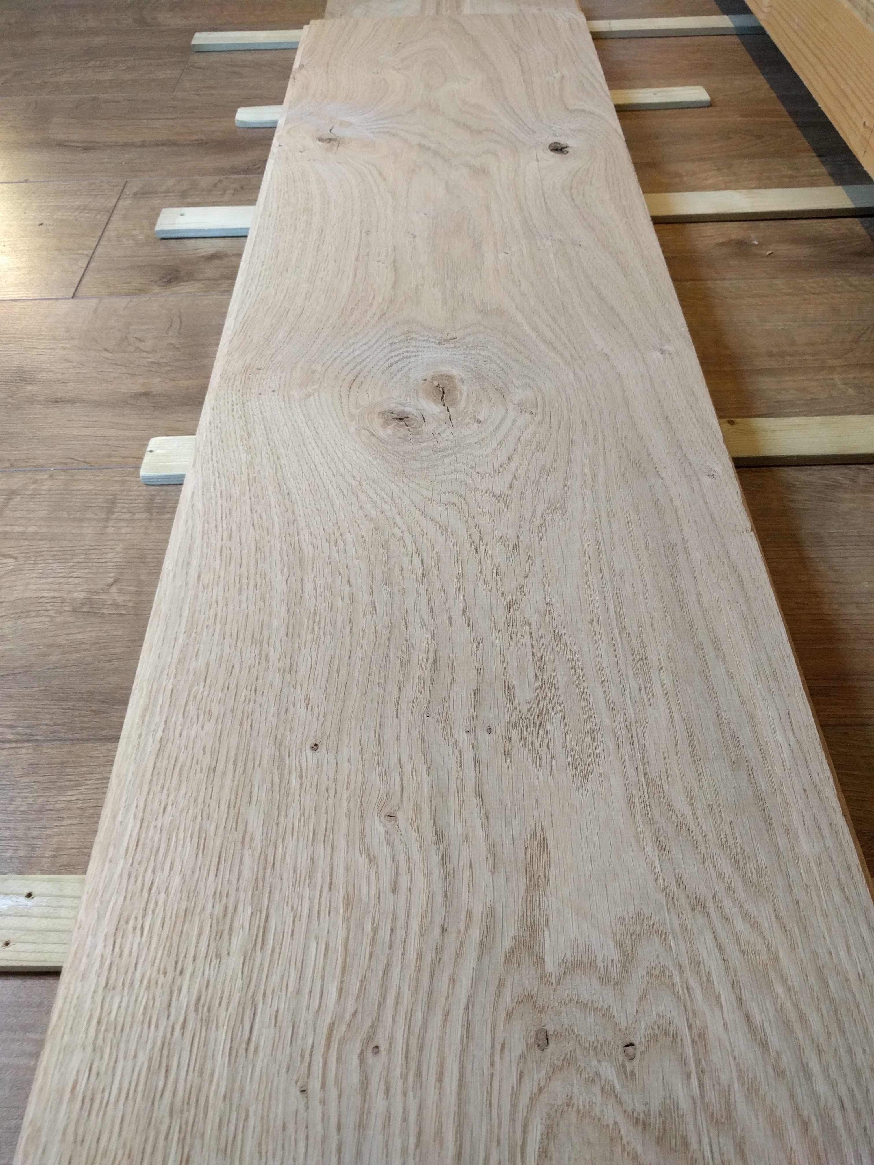
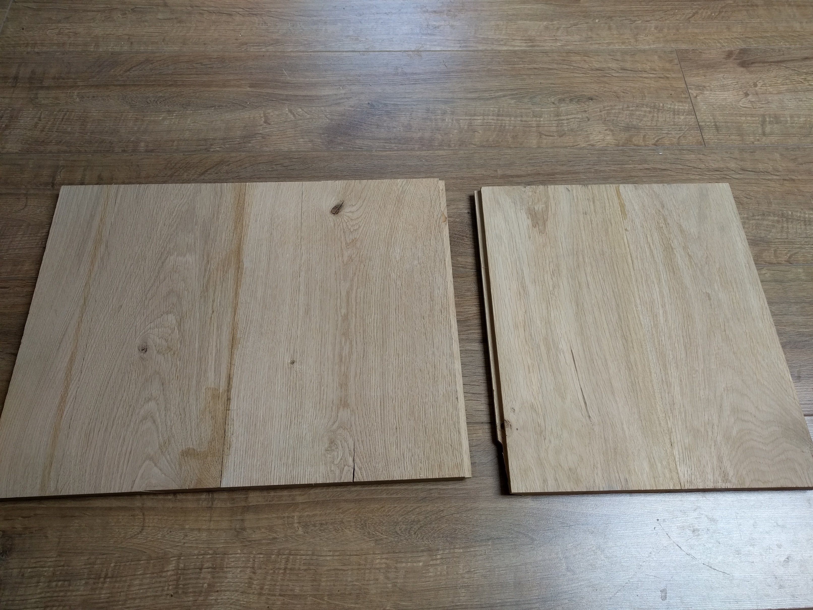
As for many of my projects I am using white oak as the material. It is a beautiful wood which I get as off-cuts from a local hardwood flooring company. They kindly let me sort through their huge pile of off-cuts when I explained my project to them, sooo thanks West Sussex Antique Timber Company!
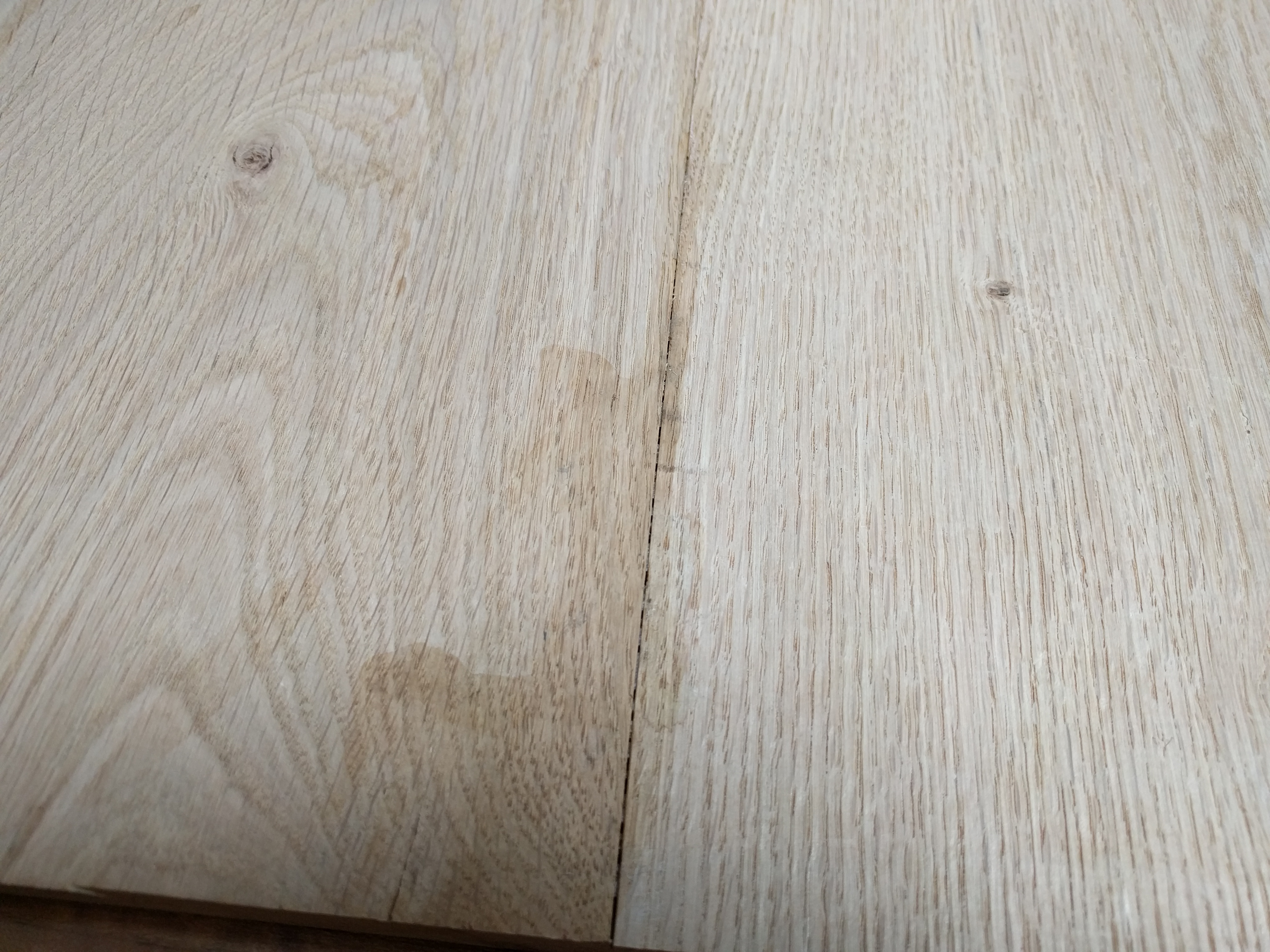
I cut the long boards into lengths of about 400mm and paired them up with other similar boards so I could glue them together using the tongue and groove joints already cut into the floor boards. Some ended up flatter than others and there were some gaps but this shouldn’t be an issue. (Nothing a bit of sanding and filler can fix!!)
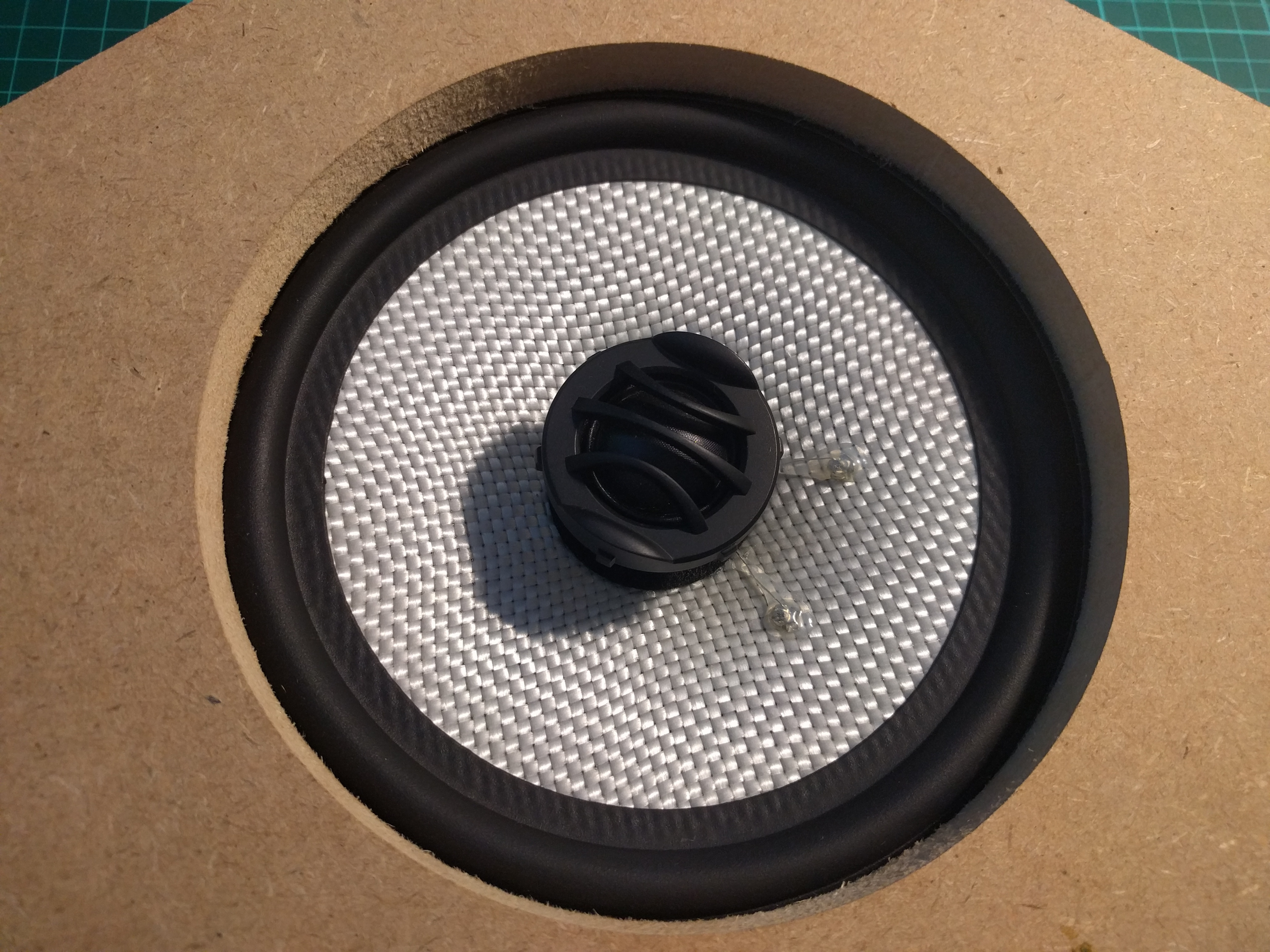
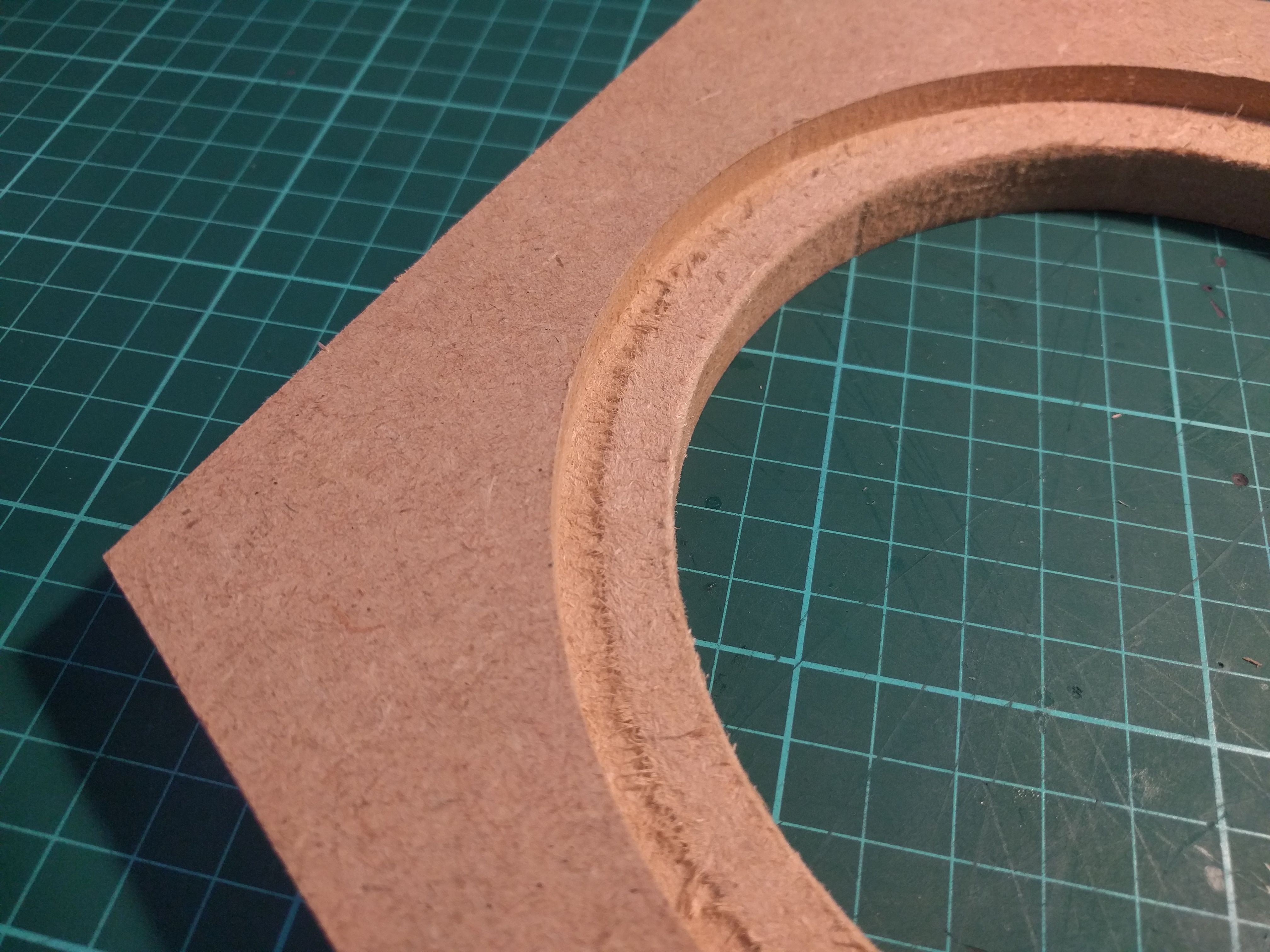
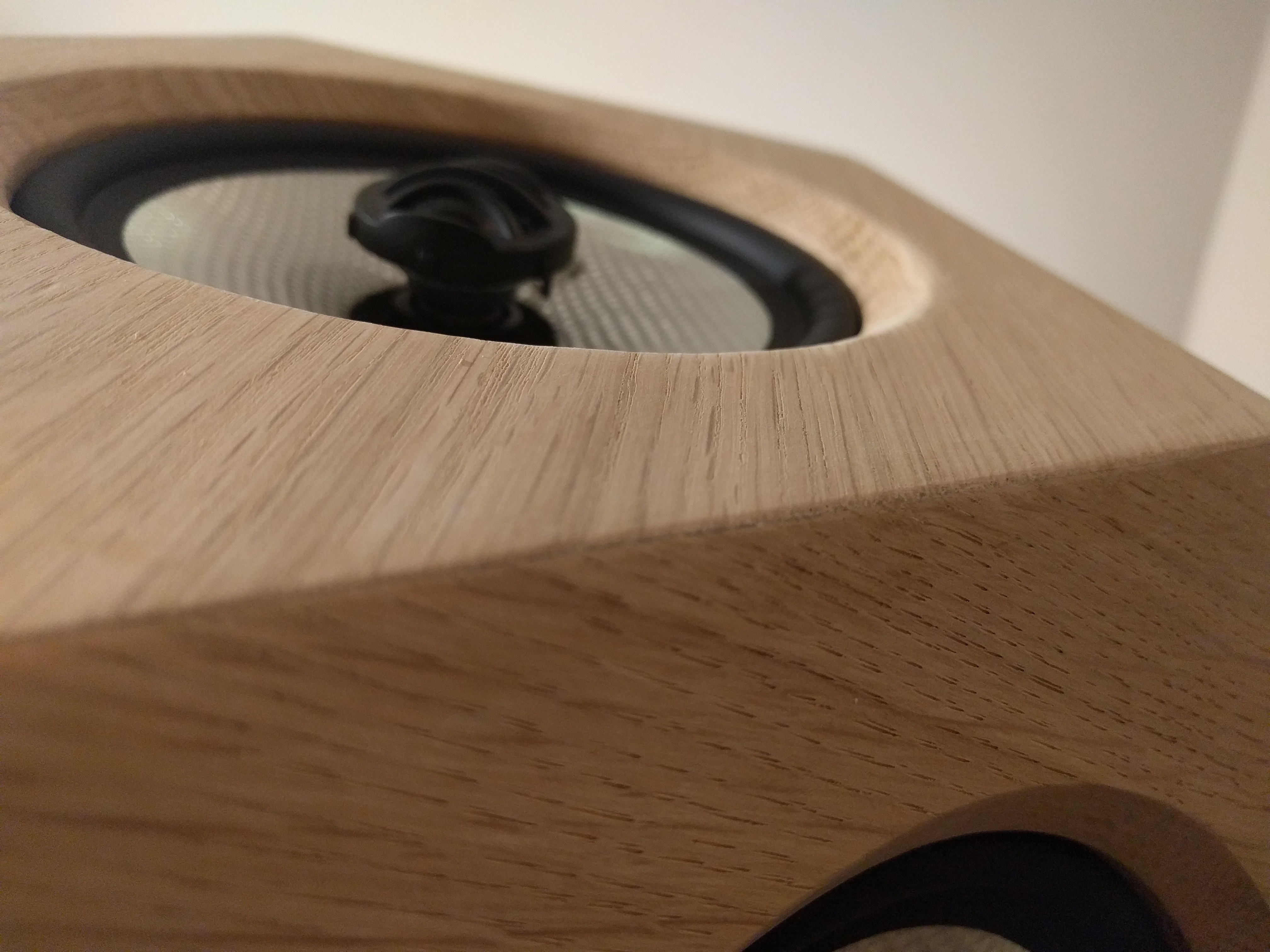
I milled a test of the hedral shape that makes up the dodecahedron out of mdf to test the fit of the speaker. It may not be very clear in the picture above but the hole cutout for the speaker was about 2mm over sized so I adjusted my CAD model accordingly.
MeshCAM did something weird on the recess for the speaker. It cut a small slot around the perimeter of the speaker recess for some reason. It thought it may have been Z-axis slippage but it was the correct depth. The rest of that recess was not cut out all the way for some reason… I thought the pencil finish was supposed to cut this but it didn’t for some reason… I am going to use Aspire for machining the oak parts as I am more familiar with it and it is reliable for me. My plan was to use Carbide Create but I couldn’t get my dxfs from Fusion to open in CC for some reason?!
This anomaly with MeshCAM did remind me that there is a lip around the edge of the speakers I have which means the rubber edge of the cone won’t sit inside the hole as I wanted it to. So for the final parts I will mill a slot to allow the speaker to sit flat.
Jigs:
I designed two main jigs to be used whilst building his project.
The first of these is my glue up jig. It is essentially a sturdy MDF frame of the angle that the hedrals need to be glued to each other at. I will make two of these so that I can clamp the pieces between them whilst the glue dries.
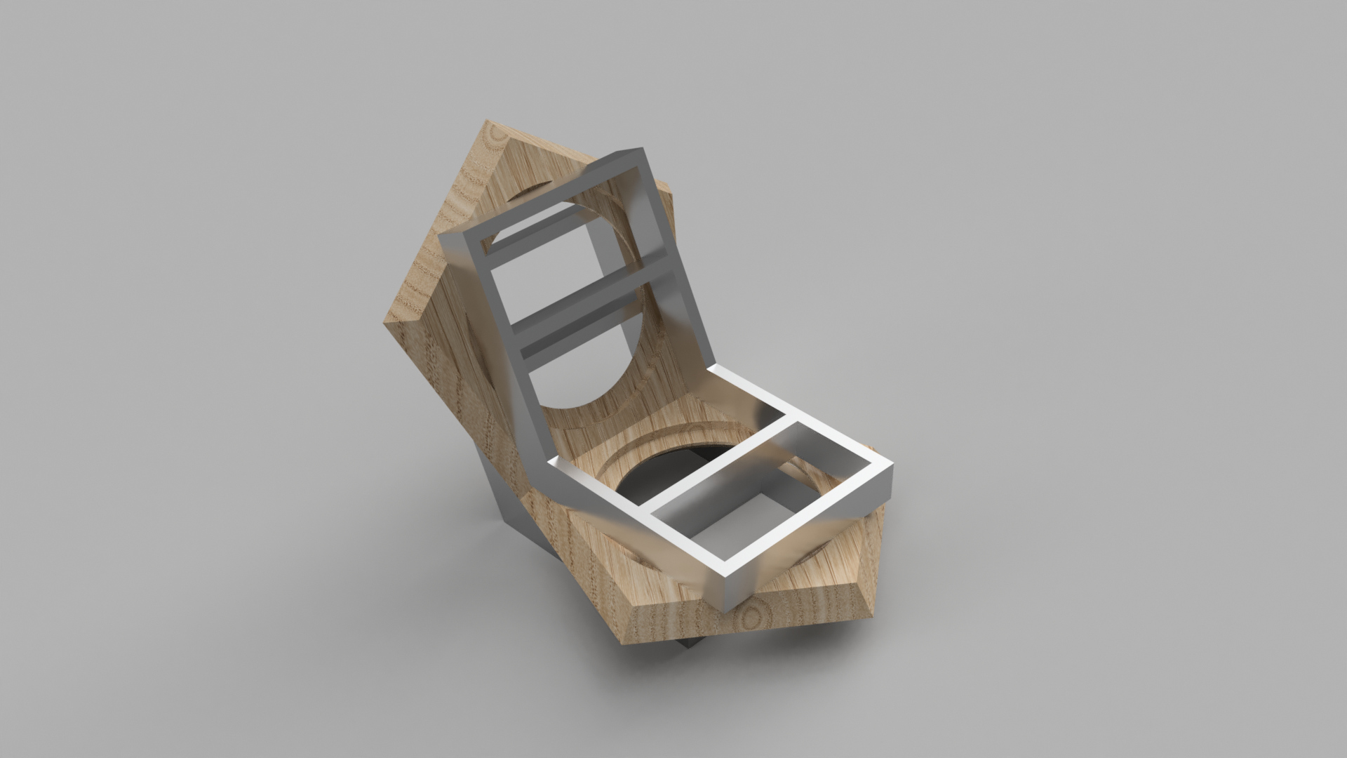
The second jig is for my mitre saw. To cut the chamfers that allow the hedrals to fit seamlessly together I was going 3D machine it but that would take too long according to some tests I did in MechCAM. So I am going to use a compound mitre saw to cut these angles. This jig helps line the pieces up to cut the angles on all sides of the hedral fairly reliably.
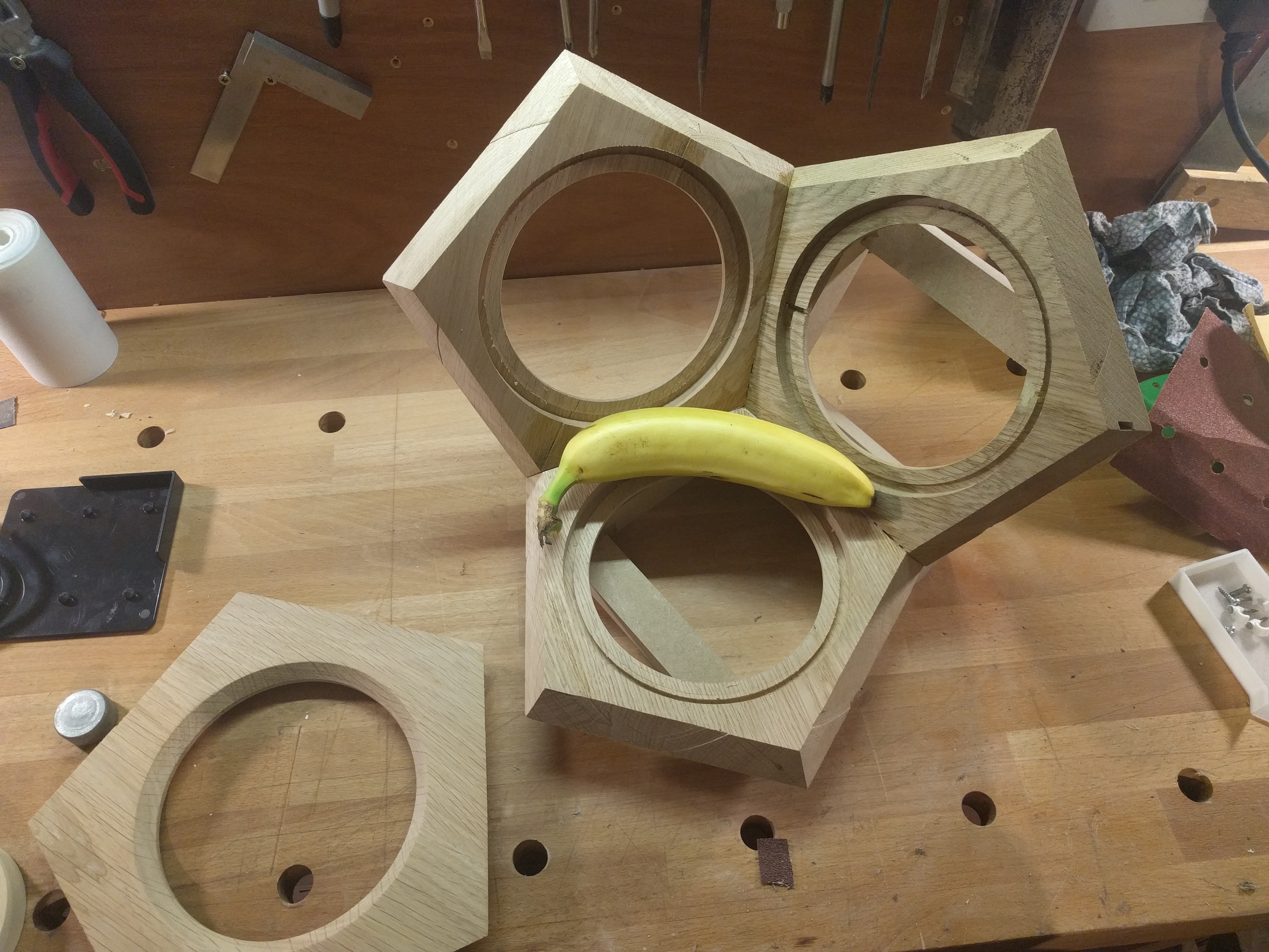
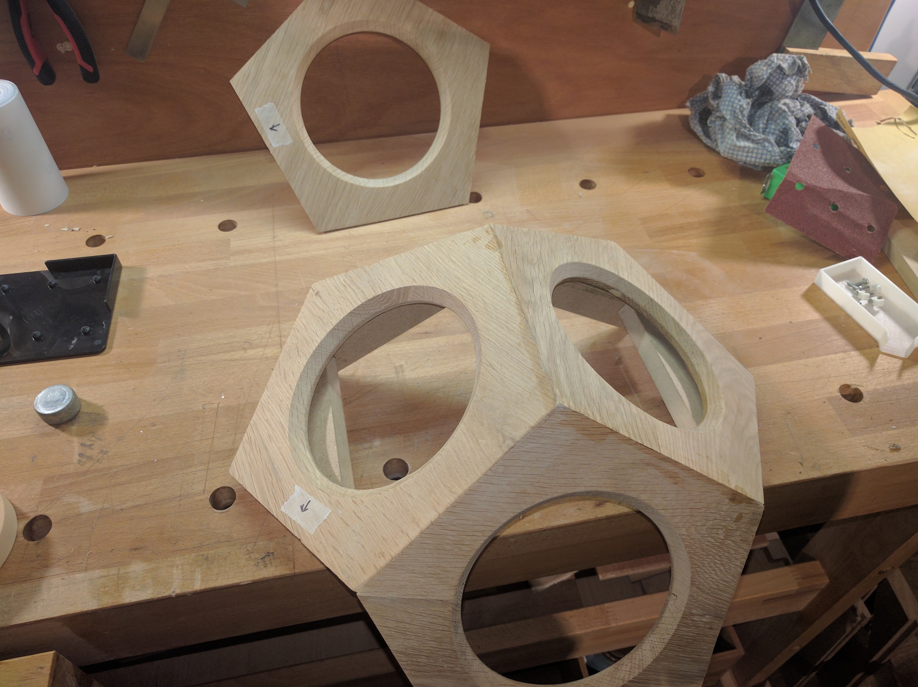
Making some progress and doing the first glue ups
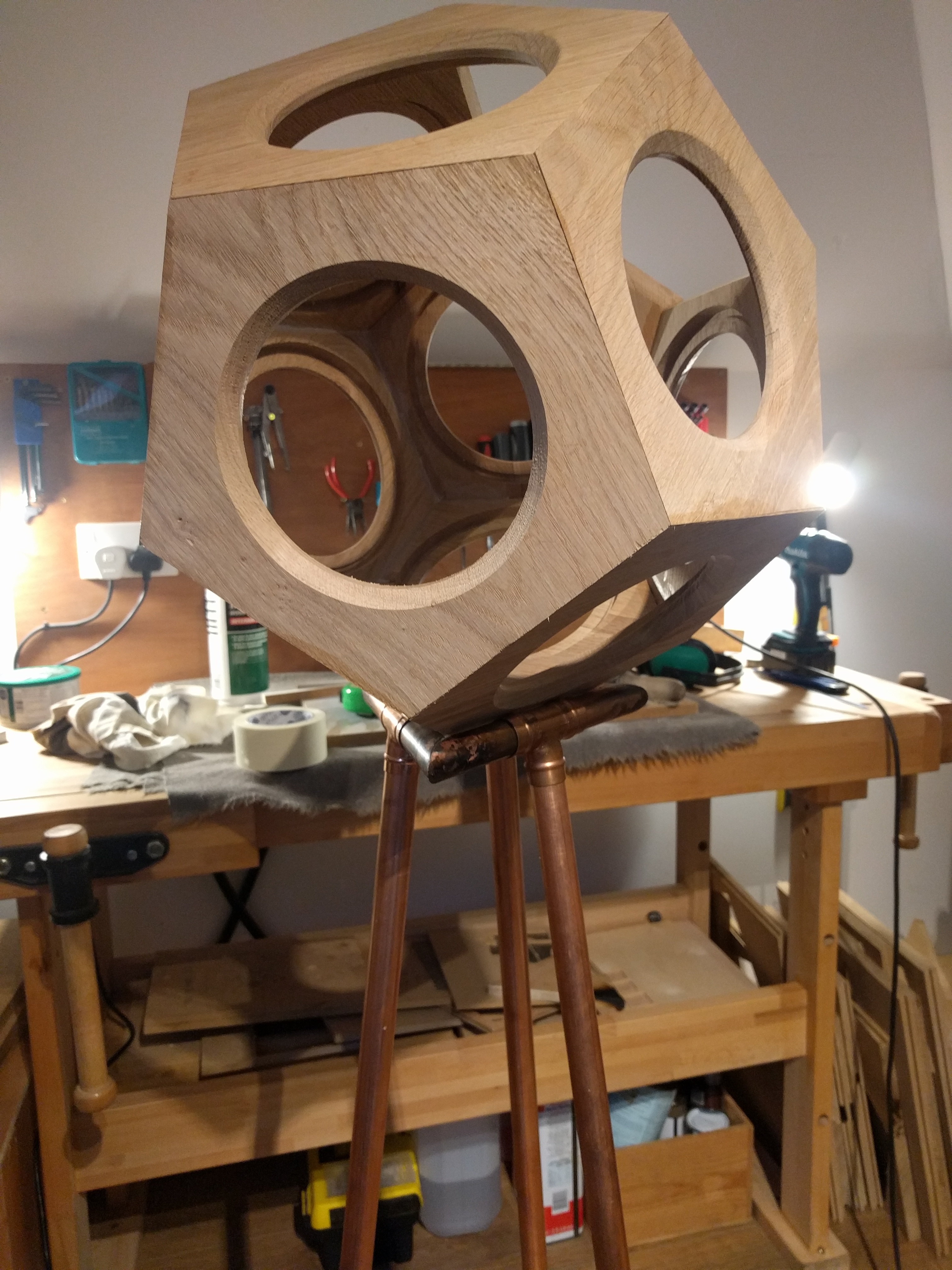
Only just realising how big this thing is going to be when all 12 hedrals come together! (banana for scale)
Edges are going to need some filler and a lot of sanding! my mitre saw isn’t very accurate…
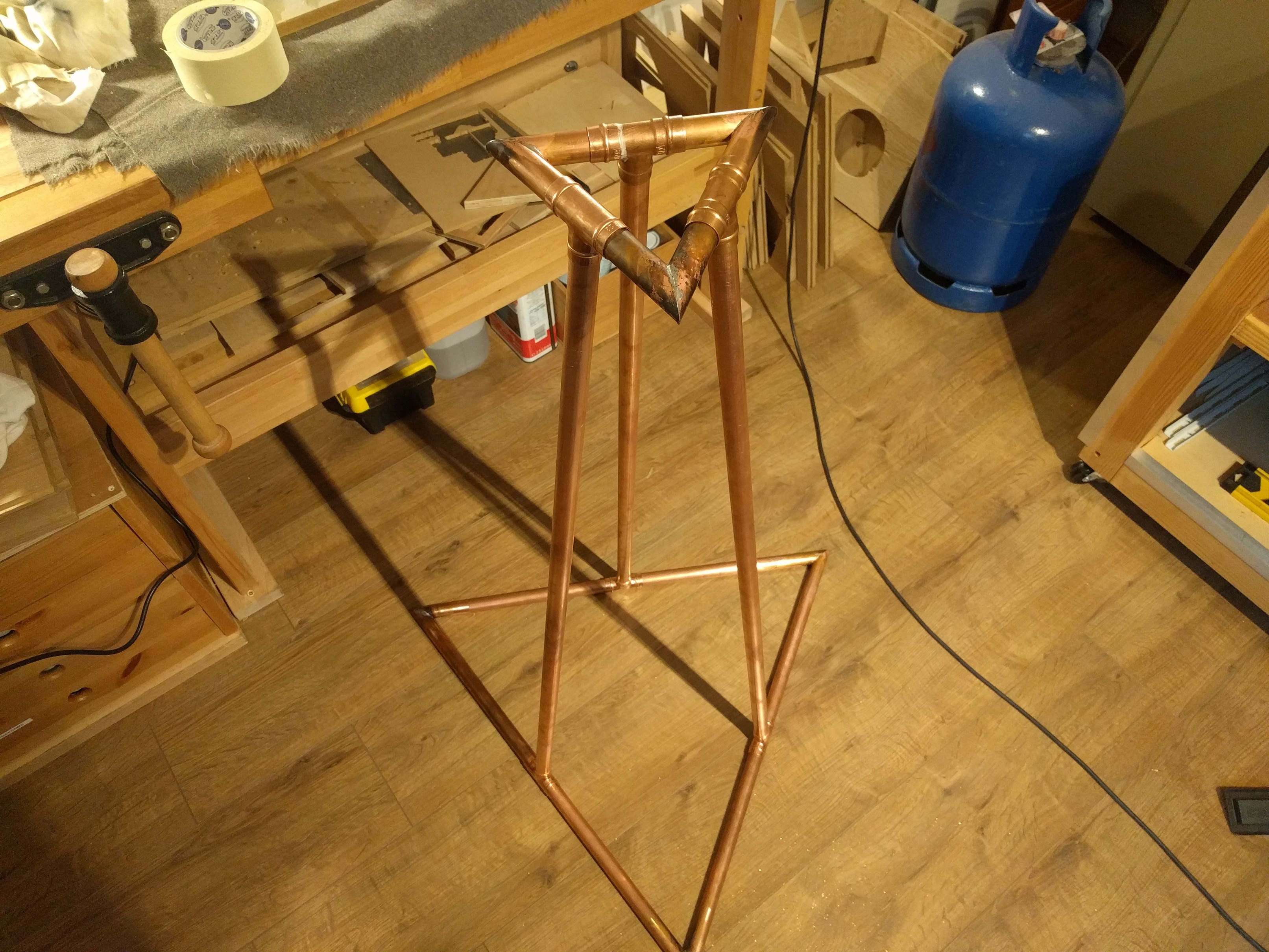
I have also been working on designing a stand for the speaker. I wanted to use copper pipe because it goes really well with the white oak of the speaker. This is my initial idea and I would love some feedback!
Also, if anyone knows how to align these two parts so the speaker sits in the stand so I can render some photos and an animation I would be grateful for some help!
Sorry I have been so bad at documenting this build on here but I have been making good progress and thought I would save it all for the video that is coming soon
I encountered an issue whilst making the base that I think the Shapeoko can solve perfectly!
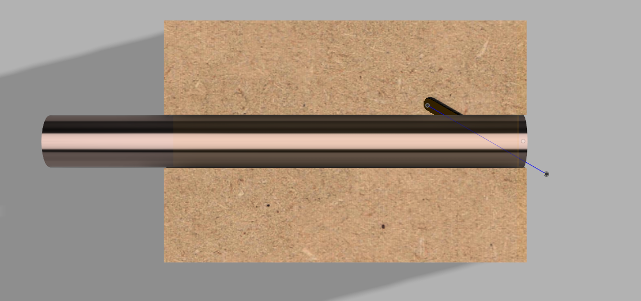
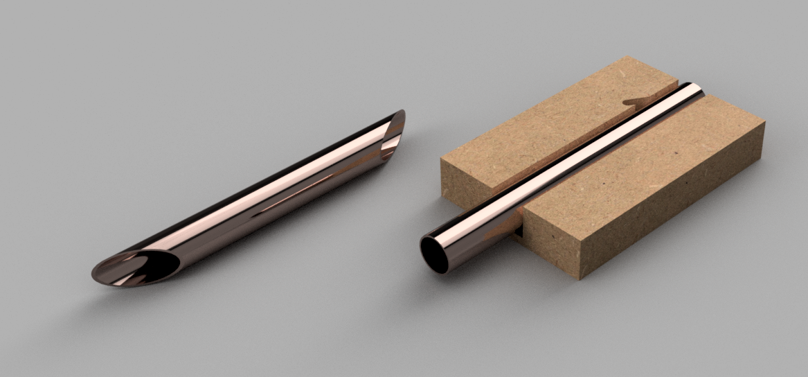
The copper pipe base consists of two triangles which need 60 degree cuts on the ends of the copper pipe to create a nice solder-able joint. Unfortunately I don’t have a mitre saw that can cut that angle so I thought why not do it on the CNC!
I came up with a simple jig that the copper pipe can sit snuggly in and be clamped in place if needs be. I can then run a simple follow path job on the cnc that can cut the end at a a perfect 60 degree angle!
The trick will be getting he jig the right size so that the copper pipe sits tightly enough inside. I’m going to try this out tomorrow and see what happens!
If it were me, I would make the fixture a bit longer so that both ends are cut without removing the part, and, to hold the part in place, cut the groove a little wide and use a dowel about 1/2 the part diameter laid on top between the part and one side of the groove to wedge the part down and against the other side. A screw into the base and a washer large enough to grab the dowel (or, if you want to go fancy, a finger type hold down) apply down force to the dowel.