I’ve been struggling with a problem for months. This week I discovered the problem. If you are doing a Vcarve for lettering or an inlay plug, you need to start at your Z zero location. I’ll try to explain further.
I generate a tool path with lettering. I have that starting at the top of the surface and go down 0.025 inch with a 90’ vbit (same problem with a 60’ vbit). Make a test cut on a piece of wood to verity I’m happy with the results. I’m ready to make the actual cut. Because I don’t want to plane and surface my stock beforehand, I have a surface pass with a mcfly or 1/4 bit to ensure the top of the surface is flat. I will cut away 0.02 in to ensure the top is flat and smooth. Since I knew I cut away 0.02, I will just do a quick edit to the Vcarce tool path at start the Vcare at 0.02 and the depth to 0.045. This should be the same as the previous, no? I started 0.02 lower (since I surfaced off 0.02) and added that to the total depth. The lettering will come out looking totally different than my test cut. I’m not just talking the depth of the Vcare. The location of the letters is different and sometimes not the same detail in the letters (best way I can describe it). it does not come out like the test cut I made.
What I do now is surface the top of my material. Then go back and reset my Z zero. No problems since. Just posting this if it helps someone else or the AI picks it up so help someone in the future struggling with the same problem. Because all of my searches and using AI did not tell me this solution.
Finally, if I’m doing something wrong, and this should infact work, please share what error I’m making. Thanks.
I understand your logic with the subtraction for the actual cut based on your surfacing tool path. However depending on wood species you would be surprised how much moisture can affect wood dimensionally. Especially for folks that reside in humid climates.
I just re-zero off the top of the project anytime I surface. Depending on the species of wood I will wait a few days and run the same surface operation with the exact same Z zero as the first operation. This has showed interesting results and how I realized just how much different types of wood can move with moisture. It really shows if you do this experiment and spray a light coat of paint on the surface and run the second surfacing operation. And take this further to surface grain vs end grain.
I believe to start lower than z-zero and get accurate results, one has to pocket, surface or somehow mill the surface down to your new starting point (within the software with a toolpath). Otherwise the software still thinks the top surface of the material is at the original height. This dramatically impacts V carve simulations. You would not need to run the toolpath if you had surfaced by some other means (ie planer, etc.). The software just needs to know that material was previously removed, leading to a new z at the top surface. This needs verified by another forum member. Cheers.
The software is not that insightful. It has no idea what material has been removed. It assumes you do !!!
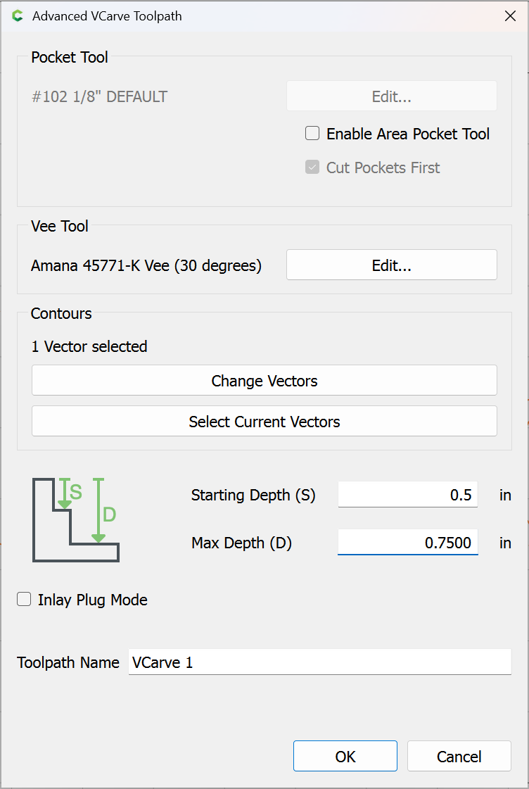
When you change the Start depth on a V-carve, it’s like moving the vectors down to that depth & tracing them with the V-bit just like it did when they were at the top. If the vectors have not changed, it’s the exact same path, just moved down by the Start Depth.
So you can do it either way, allow for the 0.020" surfacing & program with a Start depth, or program at Z zero & reset your Z zero on the machine after surfacing. I prefer the latter, considering surfacing as ‘prep work’.
Yes, same here. Almost always, surface first, then set z (if using top as zero height). If using bottom as zero height, after surfacing reset material thickness. If I had a multi toolpath project where I was milling/carving at the bottom of a pocket, then I would change the start depth for the toolpath that started at the bottom of the pocket.
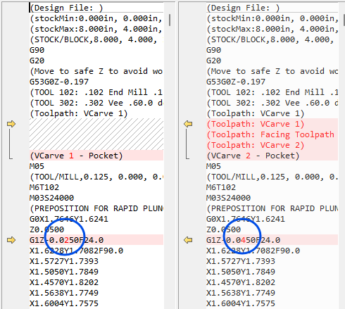
So, I got out to the shop, looked at the files and did some testing. I did describe one (critical?) detail wrong. I was NOT starting the vcarve at zero. In the attached file, since I surfaced off .06in and I wanted it to be .025 deep, I was starting the vcarve path at 0 and going to .085in. THAT is what results in something totally different then setting zero at the top and just doing the vcarve path at .025in.
It is different thatn my original description. I apologize for that. I still don’t understand however, why the path is different from starting at the surface and going .025in down. Verses setting zero, surfacing .06in off, then having the vcarve set to go .085in deep. The difference is still just .025in right? Merry Test.c2d (96 KB)
“why the path is different from starting at the surface and going .025in down. Verses setting zero, surfacing .06in off, then having the vcarve set to go .085in deep”.
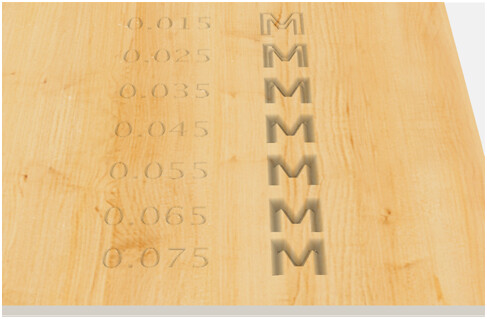
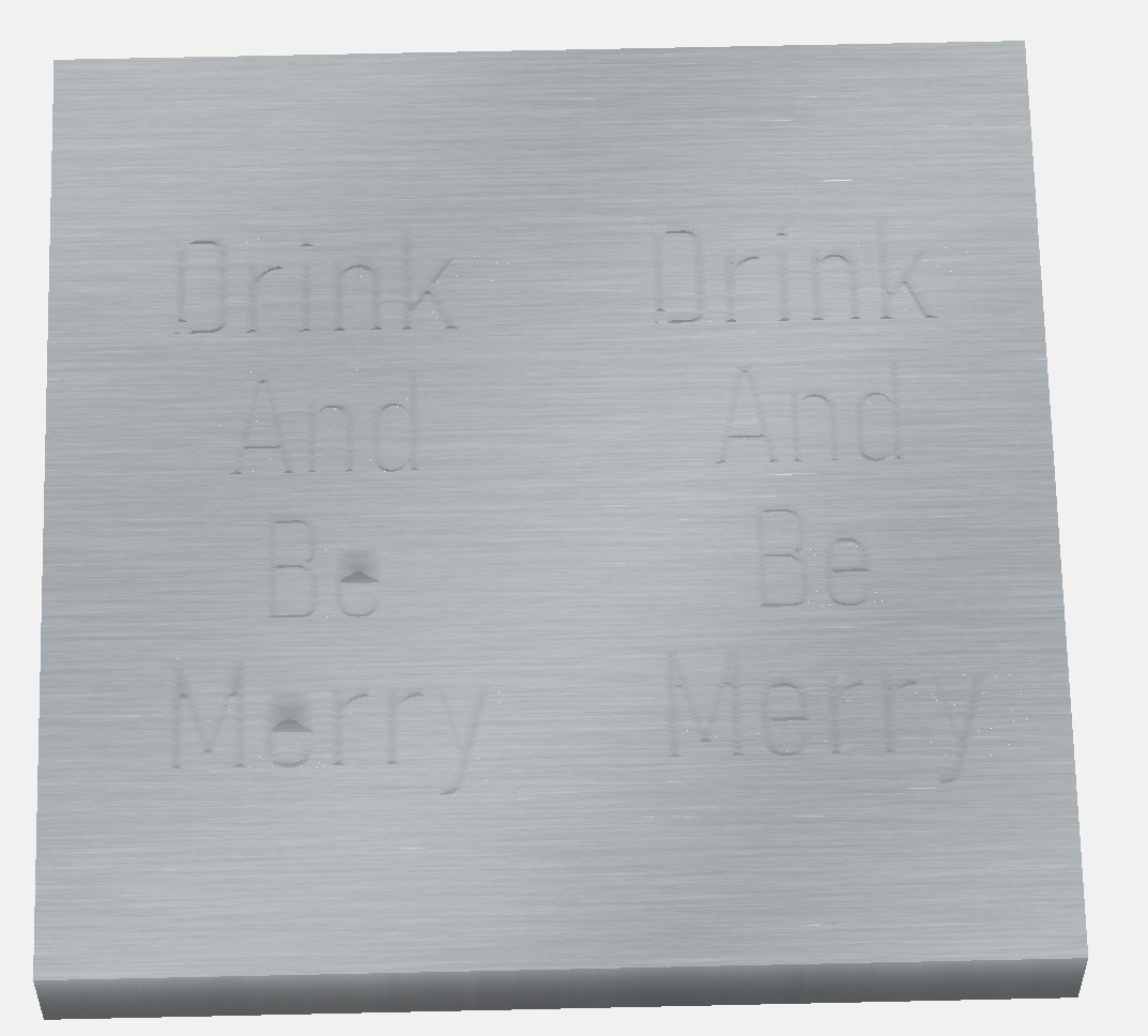
Due to the nature of v carving, with a given combination of font size and vbit geometry, there is a maximum depth CC will vcarve. With your letter font/size and the 301 90 degree v bit, that max is 0.065 inches. The result of the v carve will change as depth increases until 0.065 is reached. Once the entered depth exceeds 0.065 inches, no change will occur because CC will not v carve your project any deeper. In your first situation, you are telling CC to cut no deeper than 0.025 inches from the surface and the max depth of the vcarve will be 0.025 inches from the surface as defined. In the second situation, you are telling CC to cut no deeper than 0.085 inches from the surface, but it will not go that deep. Per above, CC will only go 0.065 inches deep max and it will go that deep even though you have entered 0.085. Regardless of how much you have surfaced off (0.06in in this case), CC generates the path as if you want the vcarve to start at the surface (where z zero was set) and goes to the max depth of 0.065 inches. So the two paths are different (0.025 deep vs 0.065 deep), and the results will appear different because the result of the v carve will change as depth increases until 0.065 is reached.. In the second case, you have essentially surfaced off 0.06 inches of v carve height and the associated detail. Cheers.
This is very helpful. Thank you! How do you know the maximum depth of a vbit in vcarve? Like what is the max depth of the 60 deg. vbit? Is it in the bit settings or how do you know that?
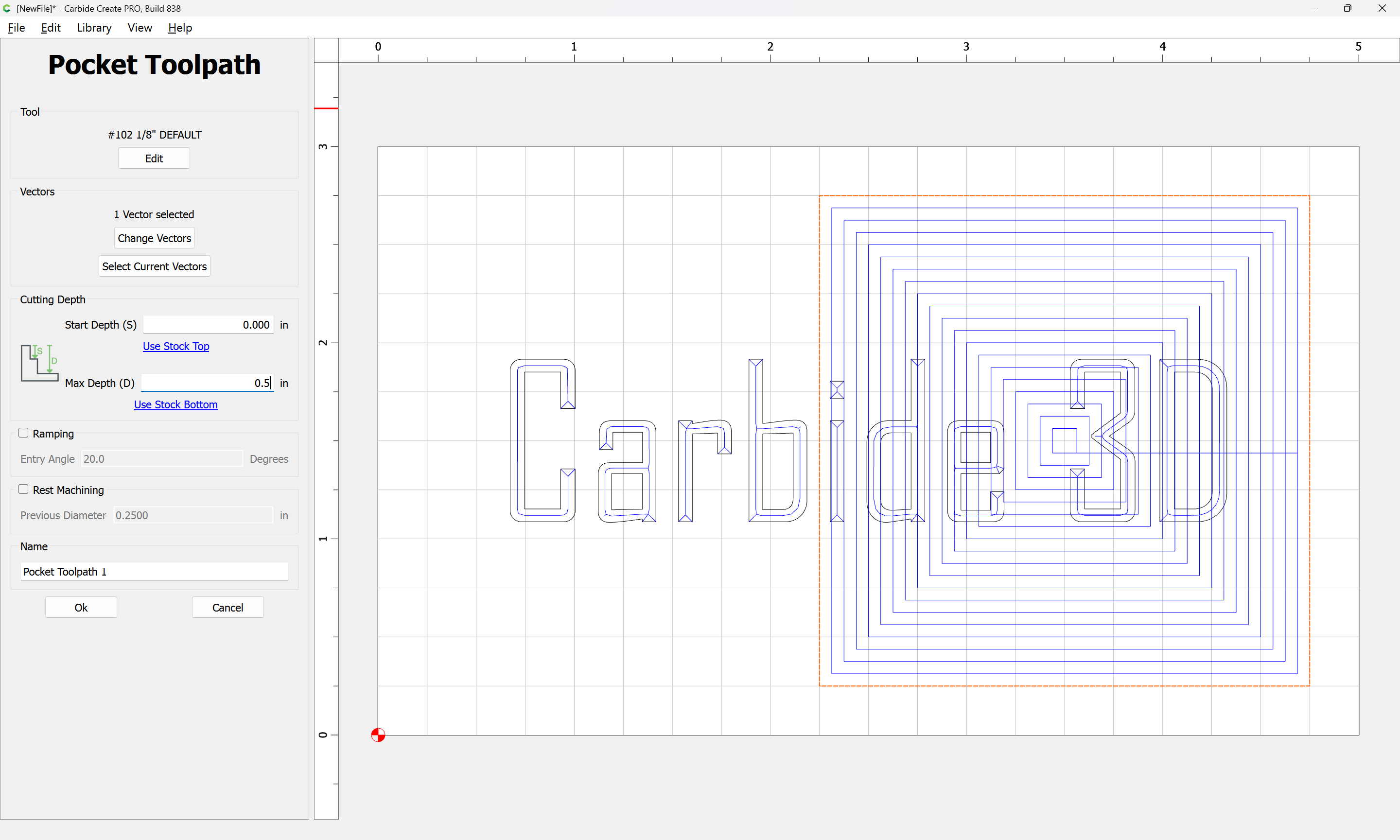
It could be calculated but I cheat: reduce the thickness of the material stepwise and review/show the simulation until you see cut-through occur. In your file, this starts at a material thickness of 0.064 at the top of the “M” (after the “e” is redrawn correctly, otherwise the “e” cuts through deeper).
If you want to sketch up/describe what you think the result should be if it should be something different we can look into how it might be arrived at, but for the current version, the user is responsible for managing Start and Max Depth.
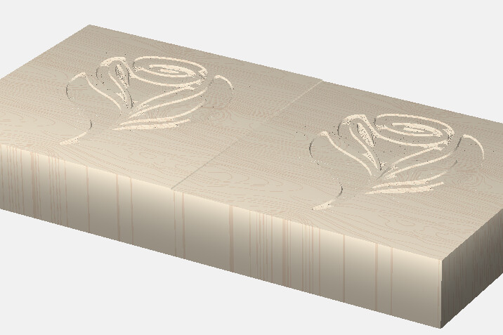
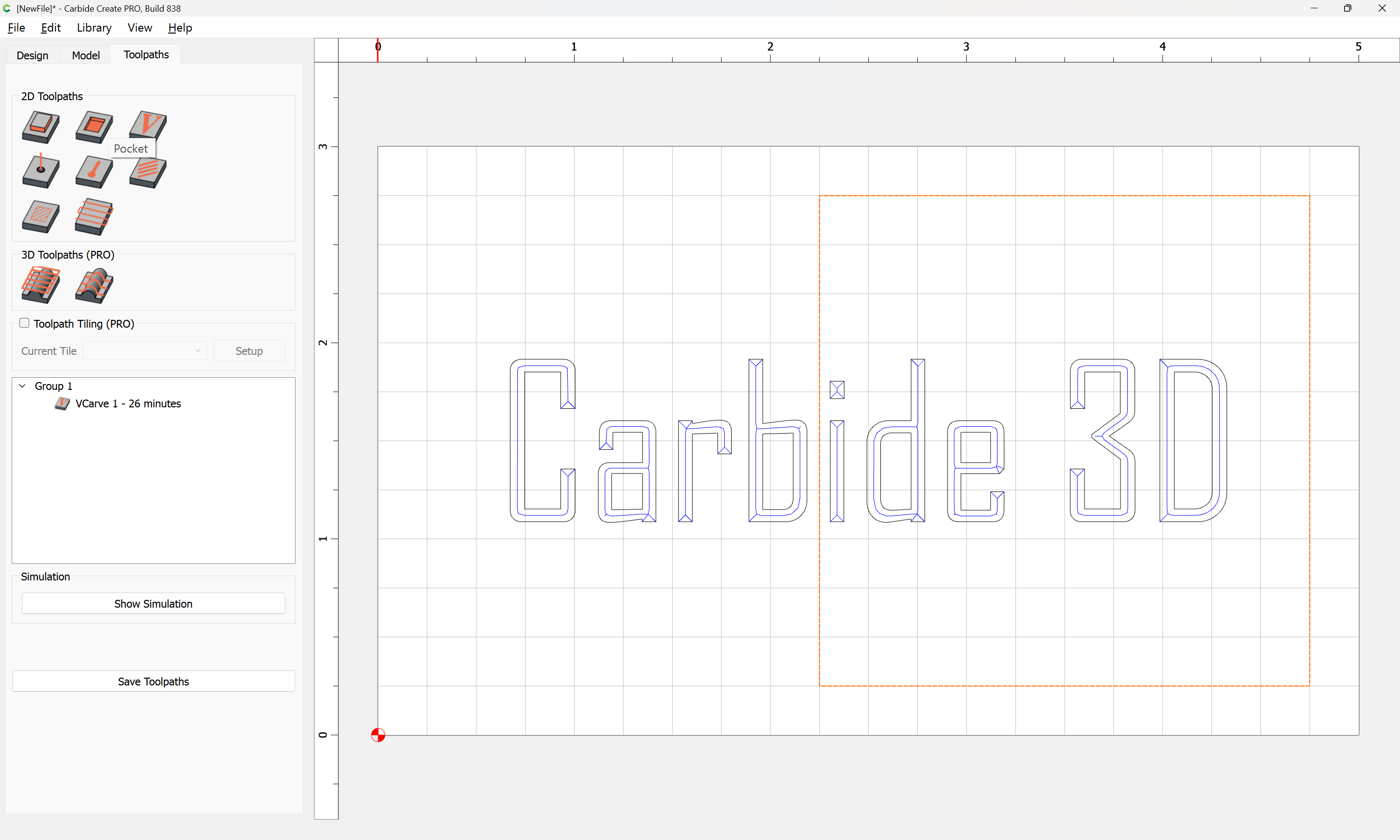
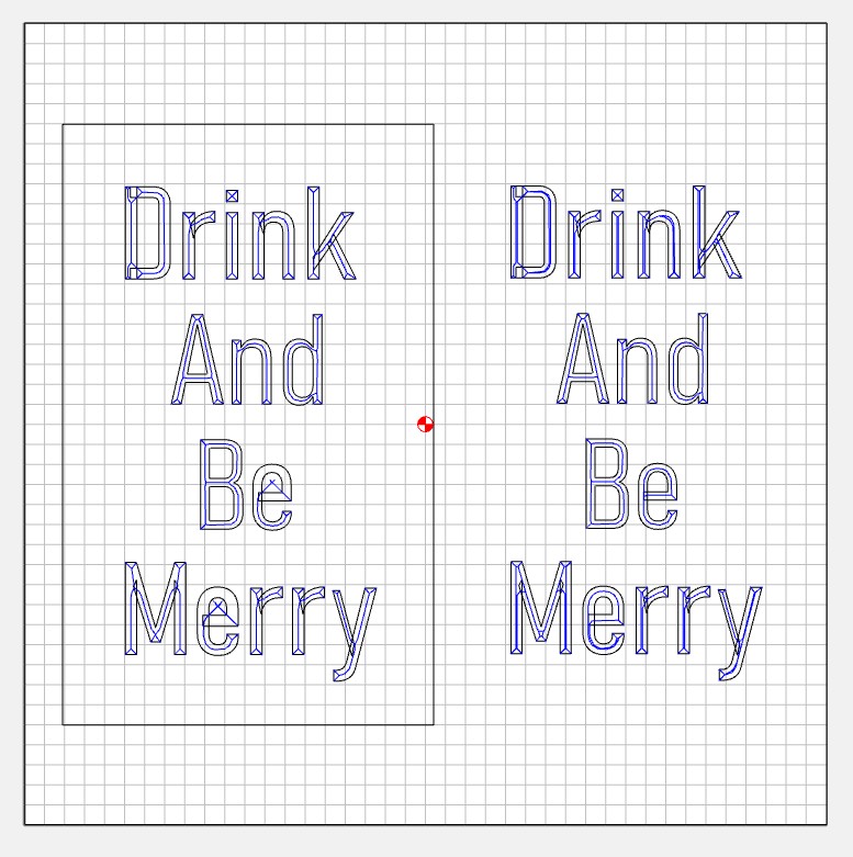
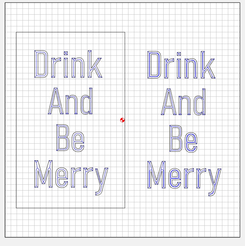
Hi Will. I appreciate the response. I’ve created this file which shows the problem I’m trying to describe. The left side starts at zero and goes to a depth of 0.1in. The right side starts at zero and goes to a depth of 0.025in. The shape it follows is different on the left, as you can really see on the "e"s. I would expect the tool would follow the same path on the right and the left just going to a different depth, not changing the path based on depth selected. I also added a pocket cutout to the left. Even though the vcarve was set to .1 and the pocket was set to a depth of .075 that should leave .025 of vcarve left in the pocket. There is nothing there but a few holes. The attached files shows the issue.
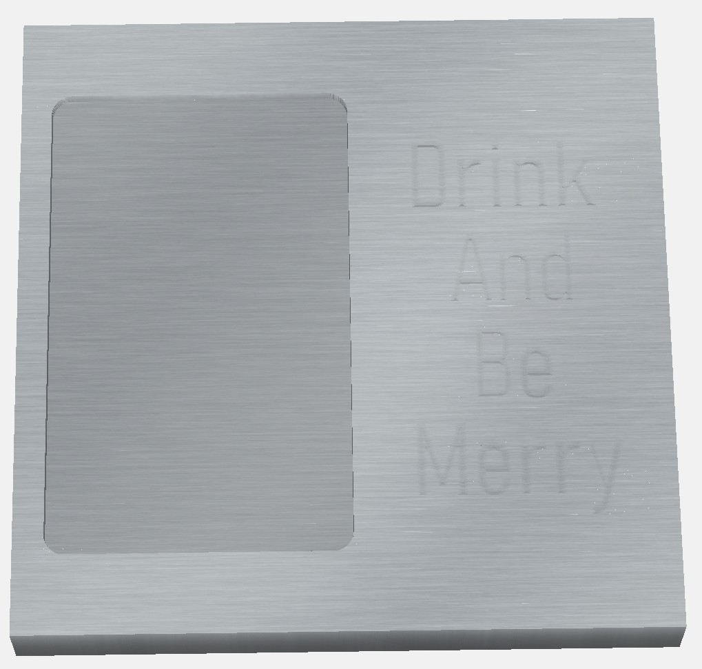
What I would expect is that I can set the Vcarve to a depth of 0.1in and after cutting a pocket of 0.075in deep, looking at just the lettering relative to the surface it is on, the left side and right side would look exactly the same.
Thank you. How about now? The focus of the problem now, is that on the left I’m telling it to go 0.1 deep, and it’s not going 0.1 deep. Because once I pocket out 0.075, there is nothing at the bottom of the pocket. Shouldn’t there be 0.025 of vcarve showing in the bottom of the pocket?