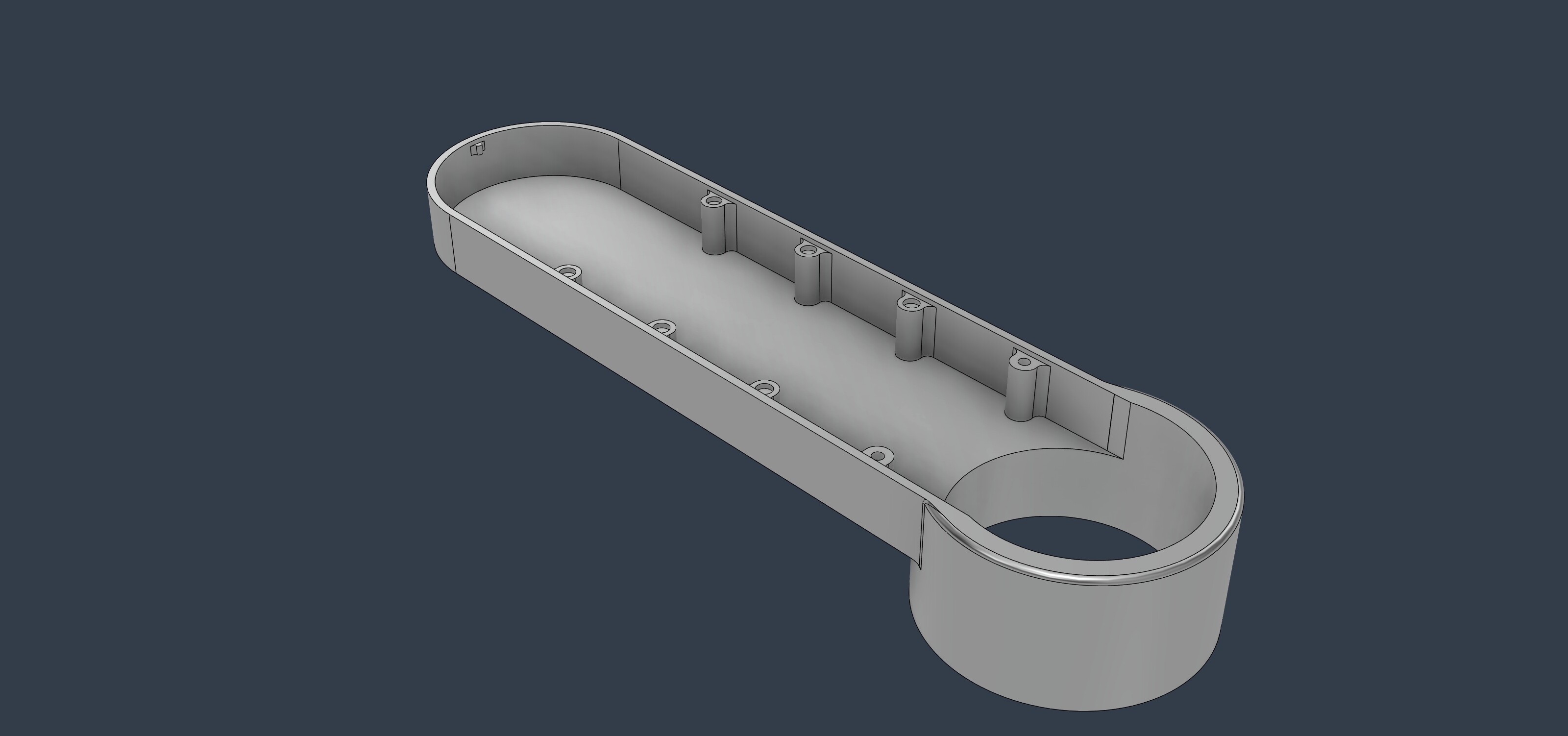
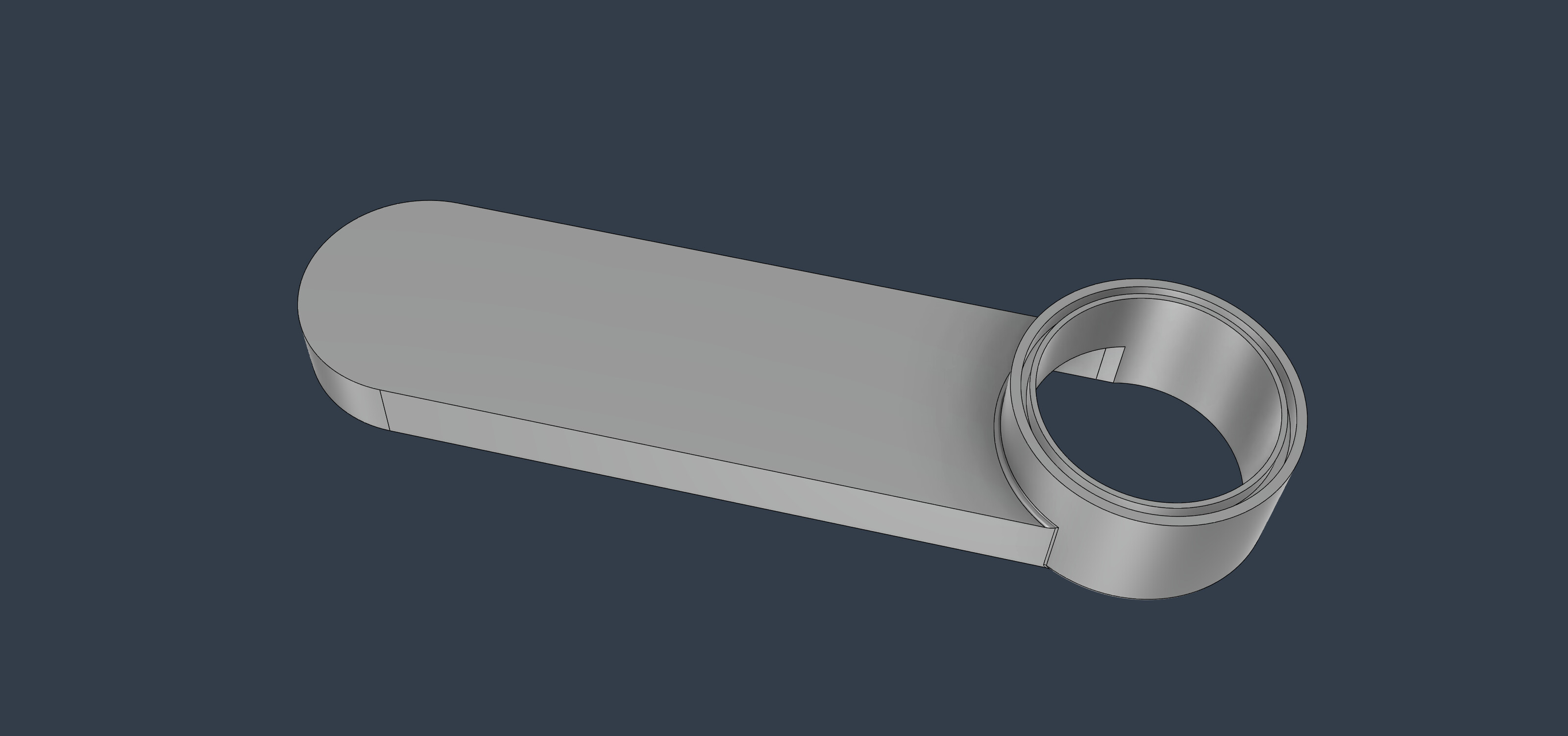
Kludged this together this morning. It has a 3mm slot to retain a brush. I can easily change that. Let me know what you think.
1 Like
Thread that first pair of standoffs or have a place to embed a nut and then the thumbscrew can come in from the top.
1 Like
I think it looks great. I’m hopeful!
Agree with @CullenS re: The thumbscrew standoffs.
ok holes thru and threaded commencing 9 hour print
2 Likes
I cut my prototype today. Looks like I messed up a measurement somewhere. Glad I did that instead of getting a buddy to print it.
Can I chip in? (Pun intended)
I’m looking to understand the issue a bit before making a judgment.
Sweepy Pro is designed to align with the head of the spindle. If you run the spindle through the body, you will reduce suction as airflow will be restricted by the spindle body.
See a couple of handy references.
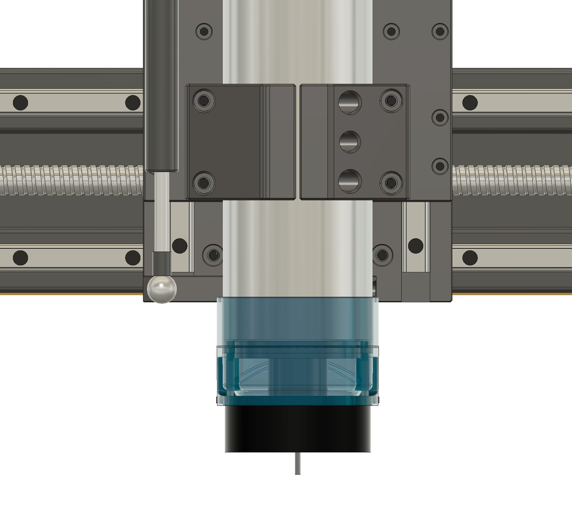
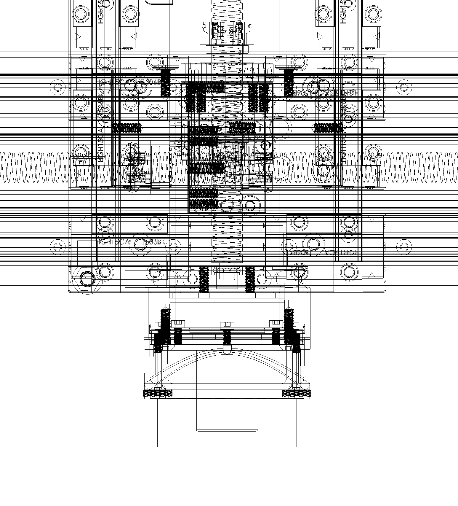
Now with longer end mills, you will find that the longer the end mill, the suction is reduced - but that is because the “sealing ring” no longer reduces air flow around the body of the spindle.
For lack of a public part no, the blue part is what I’m referring to as the sealing ring
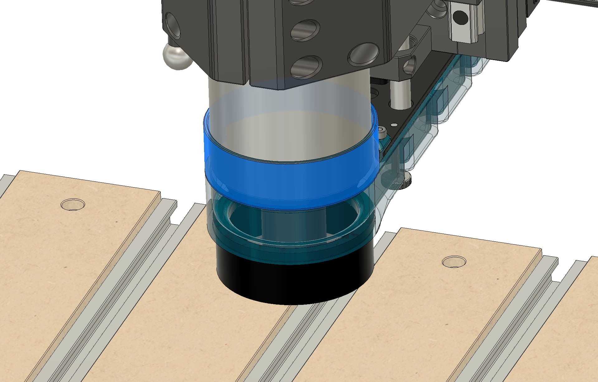
In that instance, I do have a series of different height rings that seal the spindle further up and increase suction.
2 Likes
I have the 30mm riser blocks installed and the bristles only get to about 1” above the spoilboard, that’s 1 problem I am trying to resolve. The other is that as @GJM has said the 80mm spindle hits the inside of the sweepy pro before Z bottoms out at least the way I have the spindle mounted.
I like your rings for the top portion. I was thinking of some sort of shield / shroud but this is better as long as it’s big enough for the 80mm.
Just the enabler here but my thought was the spindle wouldn’t need to pass through more than half the boot, restricting flow but not cutting it off. Also, the diameter is opened up a bit for the same reason. I like Luke’s suggestion of seal rings.
In any event, here’s V1. Gary can test it.
Edit: I’ll open up the holes for the thumb screws so they can be used correctly from the bottom. My bad. I’ve never used them before.
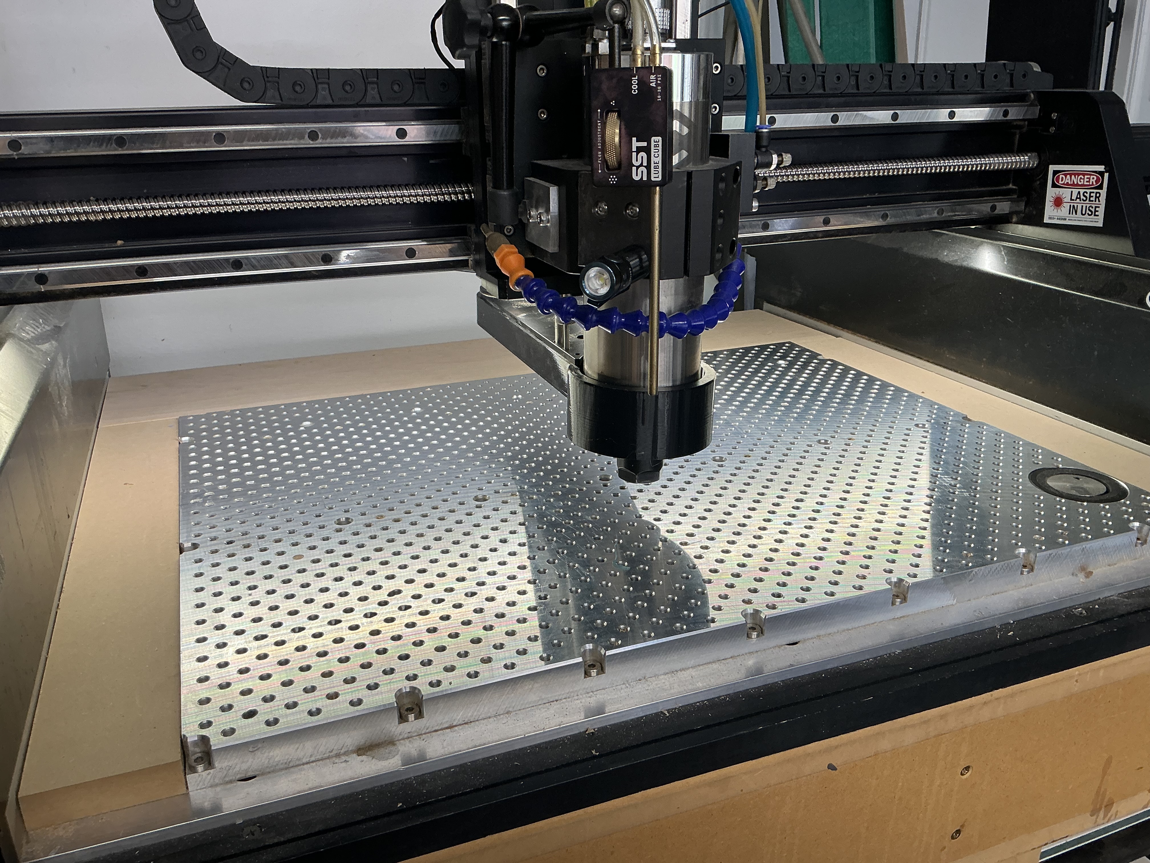
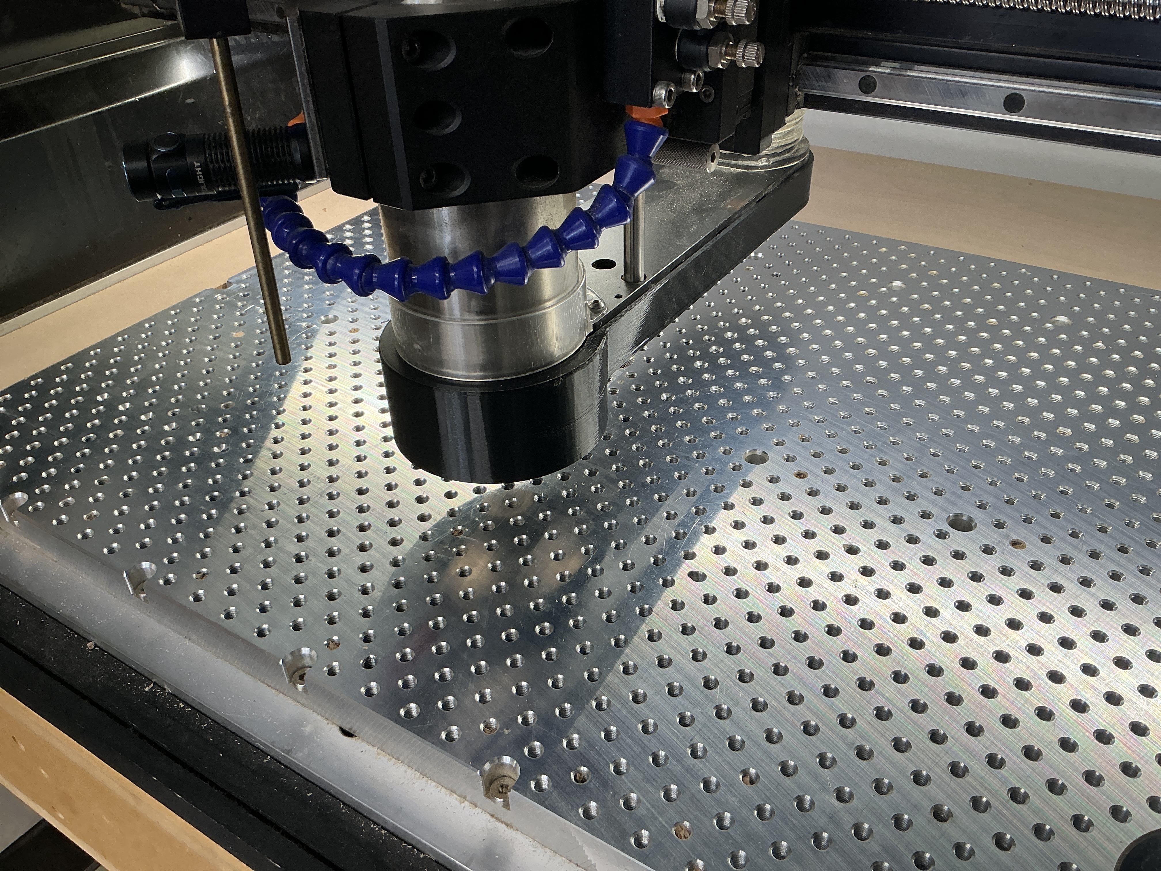
Hi Luke. The issue is that there’s a minimum distance between the spindle and the workpiece created by the boot itself. In other words, the spindle is going to contact the bristle ring before the collet contacts the surface of the wood.
Now, I suppose it could be argued you should use a longer bit, but the fact that you have to think about so much more than the CH length - you have to consider how high you’re placing the boot, how deep you’re cutting, how far down the spindle needs to travel in the sweepy to reach the depth it needs.
The flip side of the issue is that the spindle mount for the 80mm spindle (without riser blocks) will contact the top of the sweepy holder if that holder is pulled up high. This is also an issue that makes you want to lower your spindle in the mount … and then you run into the first issue more often.
The easy answer is to allow the spindle to pass fully through the boot ring (which the 65mm spindle does with no issues). You just need a different boot for the 80mm spindle.
- Gary
@luke Sorry…but this suction discussion is kind of confusing me. The 65mm spindle passes through the opening just fine and no one is worried about suction loss. I can see being concerned about loss at the top of the sweepy mount…but down below where the brushes are, we want the air to flow by…that’s kind of the whole idea…right?
I’m not following, but it’s been a long hot day, and you know us Brits don’t have AC…
The spindle doesn’t bottom out in the boot. The spindle nut, collet, taper, etc. will pass all the way through until it reaches the upper plate, as shown here.
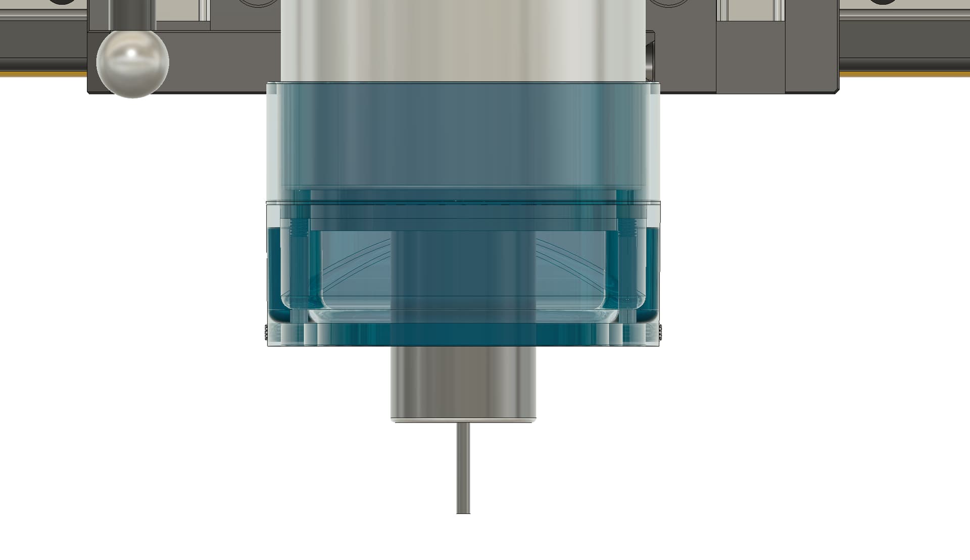
This leaves approximately 20mm × 80mm of airflow area, which is intentionally used to direct airflow from around the spindle down to the cutter and back out through the rear dust port.
If the spindle were able to pass further through the boot, it would actually begin to restrict airflow and reduce extraction performance.
The 65mm version is an adaptation that came later. The only real difference is the sealing ring. As a by-product of the smaller spindle diameter, more air can bypass the spindle when it is positioned lower, but the overall design philosophy remains the same.
If you make the boot taller, you effectively give back much of the additional clearance you’ve gained when using risers. If you make it wider, it will start interfering with the dust guards or drag chains.
The brushes should be aligned with the top surface of the workpiece. The design isn’t intended for the brush assembly to be pushed down into the material.
Can you show me exactly where the interference occurs?
1 Like
I am out of town but I hope @GJM can send a picture. The 80mm does bottom out I think even before it hits the bottom plate where the bristles are.
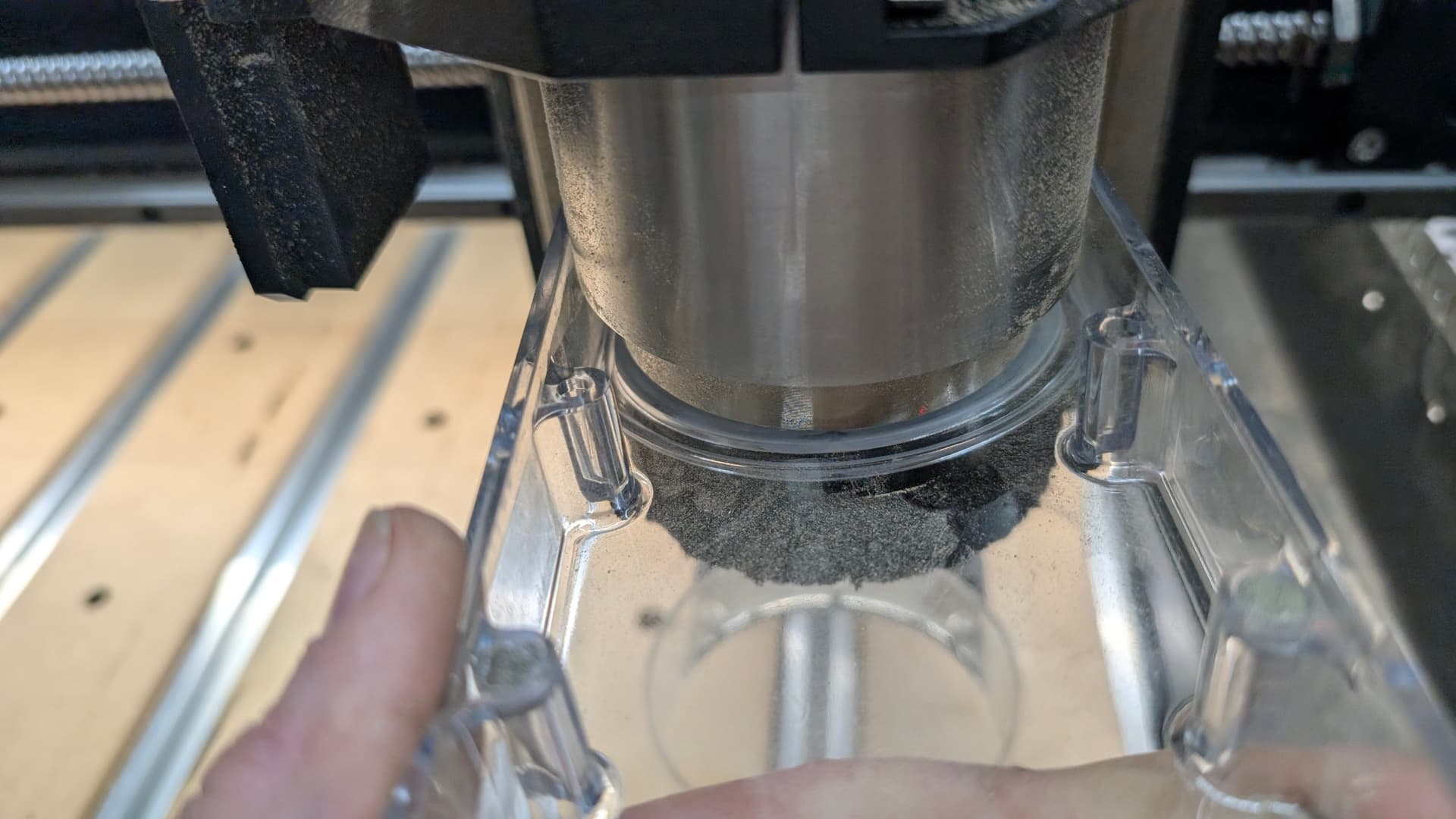
So the inner ring of the spindle cannot pass through the seal for the brushes.
I’ve run into the problem twice already…without crushing the brushes…so I know it happens before the collet hits the workpiece.
I’ll have to work on the exact example
1 Like
Yes - that is intentional - if you move the spindle past the top point here, you would negatively impact the air flow by blocking the passage with the spindle body.
Coming from a 60mm hose, we drop from approximately 2800mm2 down to 1600mm2 - a reduction of that area is going to significantly impact the ability to remove debris on deep cuts, which is incredibly important to maintain the cut quality.
This is where the spindle is designed to sit. Any lower and you will be impacting dust extraction.
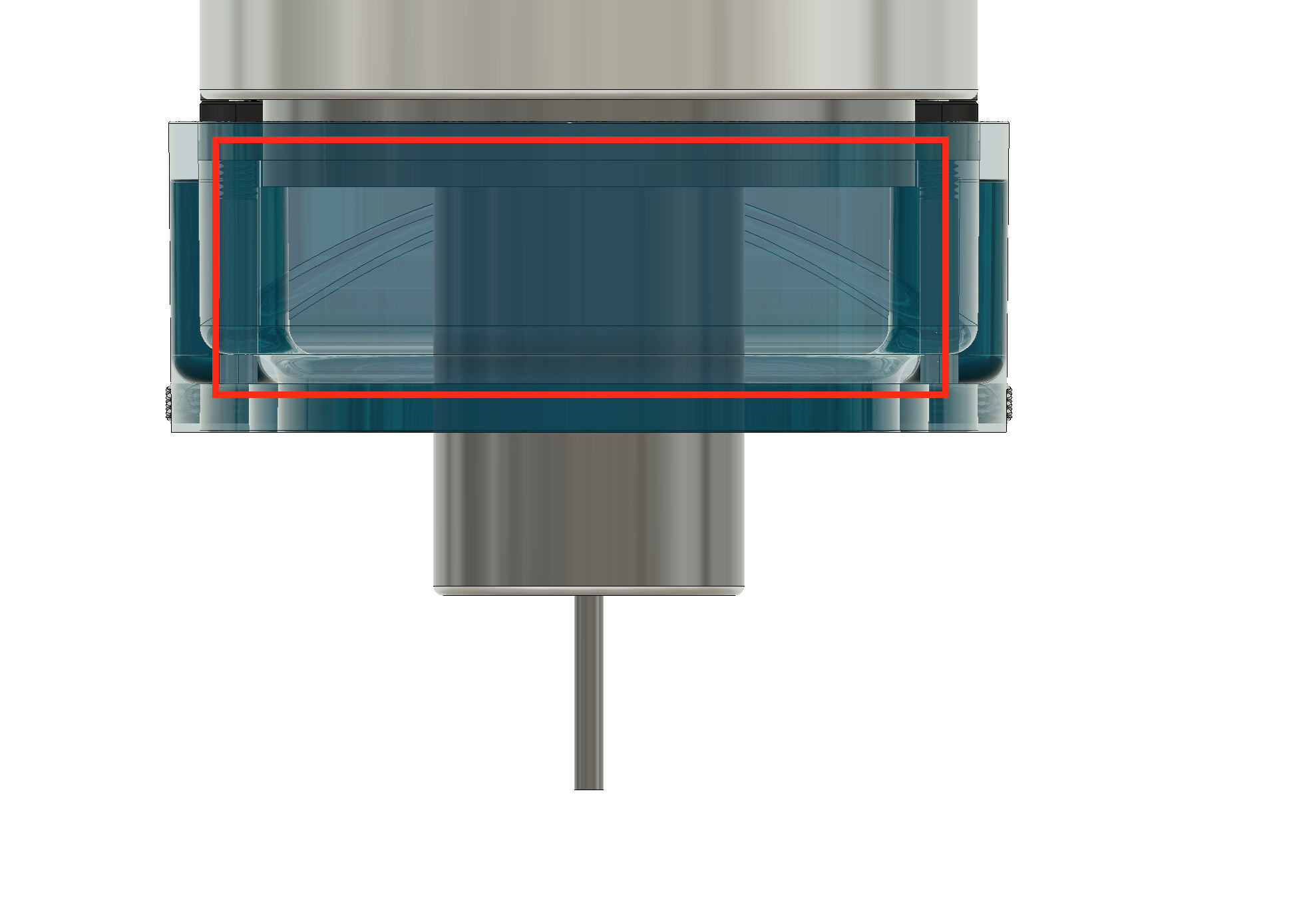
The only way to combat it would be to make the boot taller, which impacts clearance, or wider, which would likely hit the sides during homing.
Also noted that the boot can be secured just with magnets - it snaps onto the boot top - the thumb screws are a fail-safe - for those who drag the brushes deeper than the stock, which could cause the lower boot to detach from the magnets.
2 Likes
OK…but the problem is, if you do make contact, you lose steps and your piece is destroyed. Personally, I’d rather have less suction.
That’s great news. I might do away with the thumb screws then…
I’m running through the measurements
The “ideal” minimum height allows for a 20mm bit (out of the collet) to extend 15mm past the brush as standard. There is a further 10-15mm of travel before you hit the boot, which would mean your spindle nut would have passed almost 10mm past the brush end, and you would have completely blocked the vacuum.
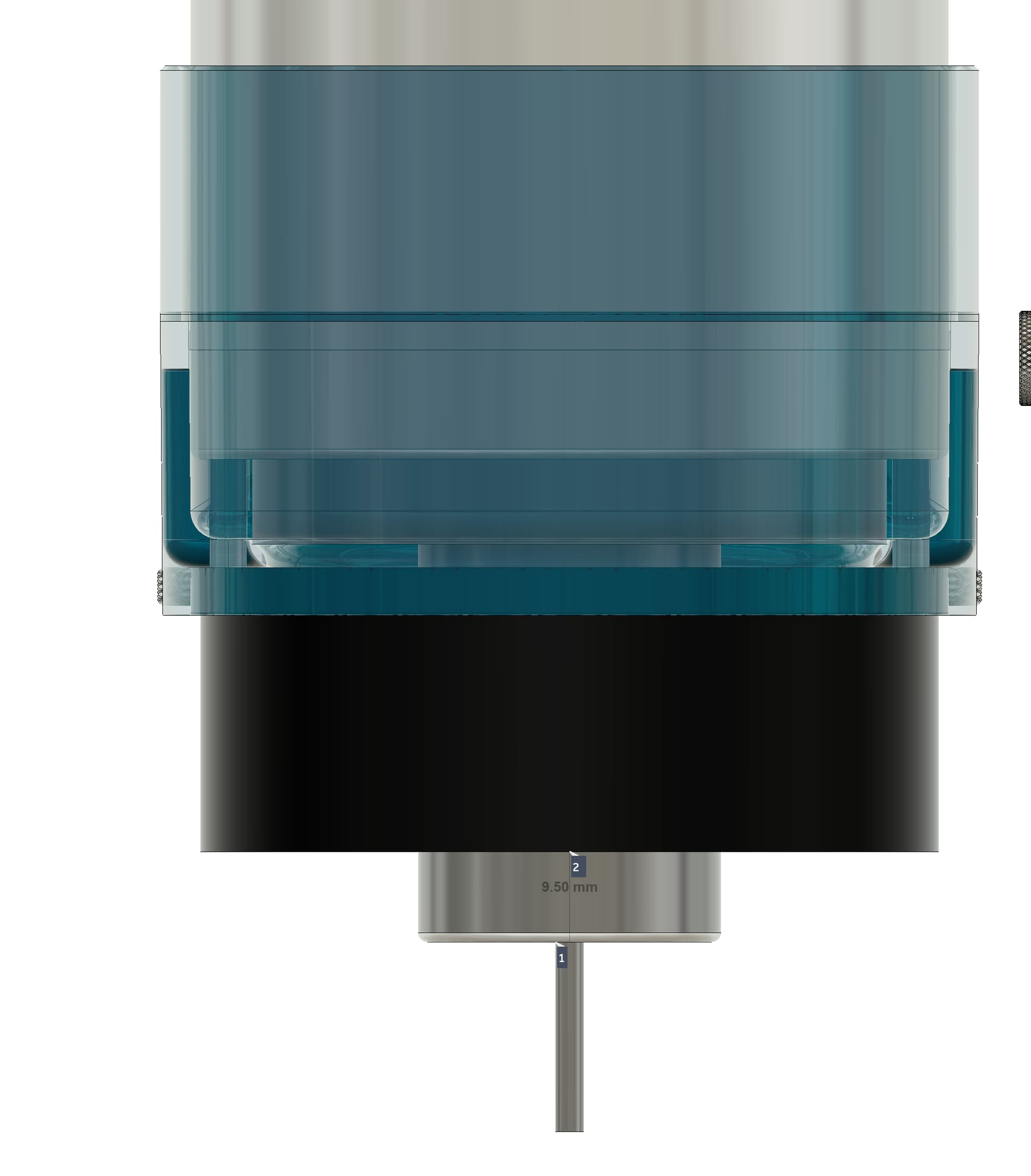
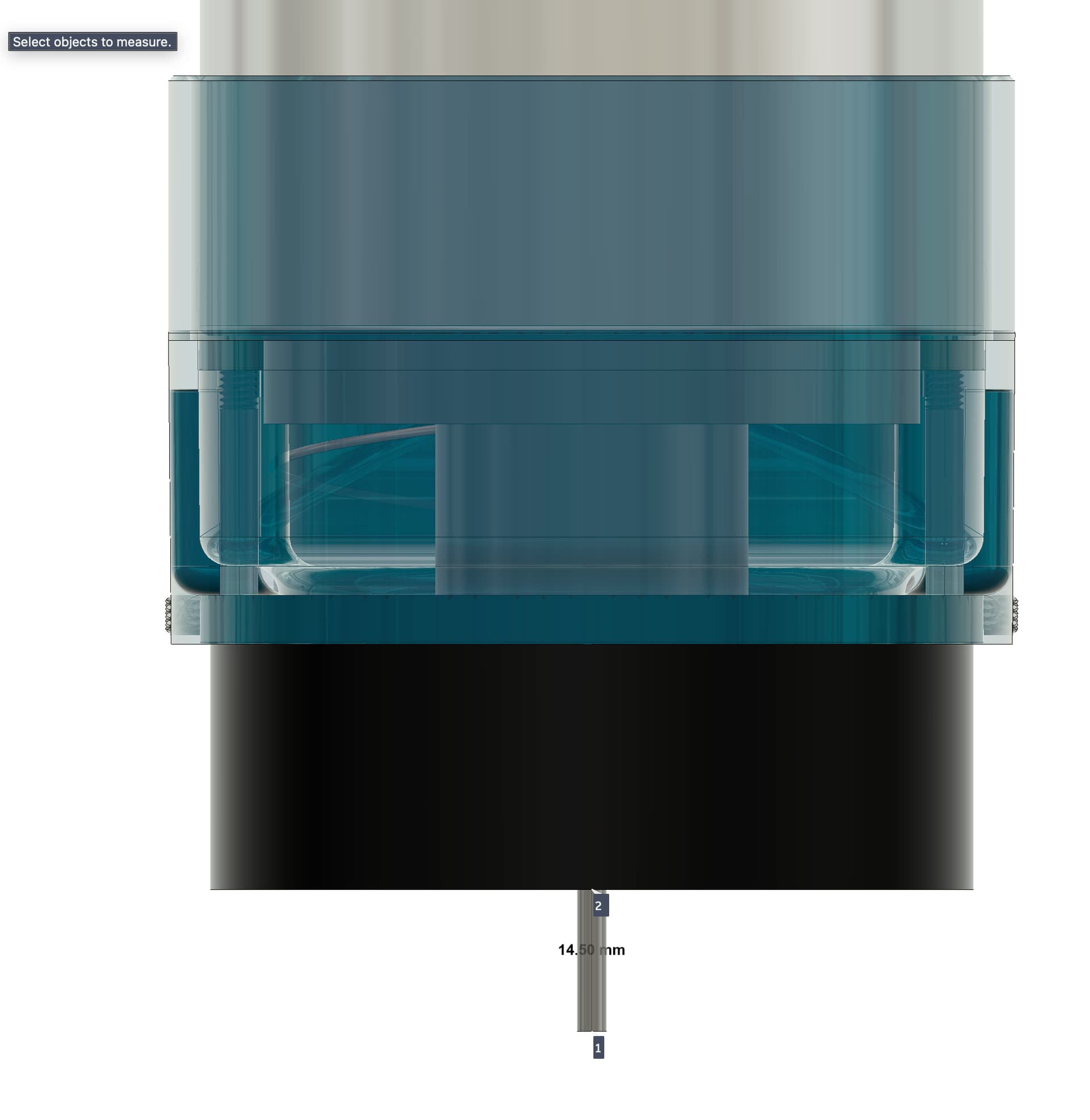

There would be a greater risk of your spindle being too high, which would mean the Z carriage is bottoming out before the bit has hit it’s maxiumum depth required.
If you think you are hitting the bottom of the dust boot than this would not be wise - you would knock it off and likely wreck it.
1 Like
I’m following your measurements. I’m also trying to figure out how I managed to make contact and lose steps on some very simple cuts. Just cutting figures out of 3/4" stock with a 1/4" bit. Twice. Your measurements would indicate that should never happen…but it did. So I need to look closer.
One thing we might try with respect to suction is to simply put a large fillet on the bottom of the rectangular opening that chips are pulled through. I’ll send an image when I’m back home.
Magnets are available on Amazon. I didn’t install any because I don’t know the polarity of the ones on your base.
Also, here is the STL of the original design if you want to have someone local print another.
PassThruSweepy.stl (1012.5 KB)
EDIT:
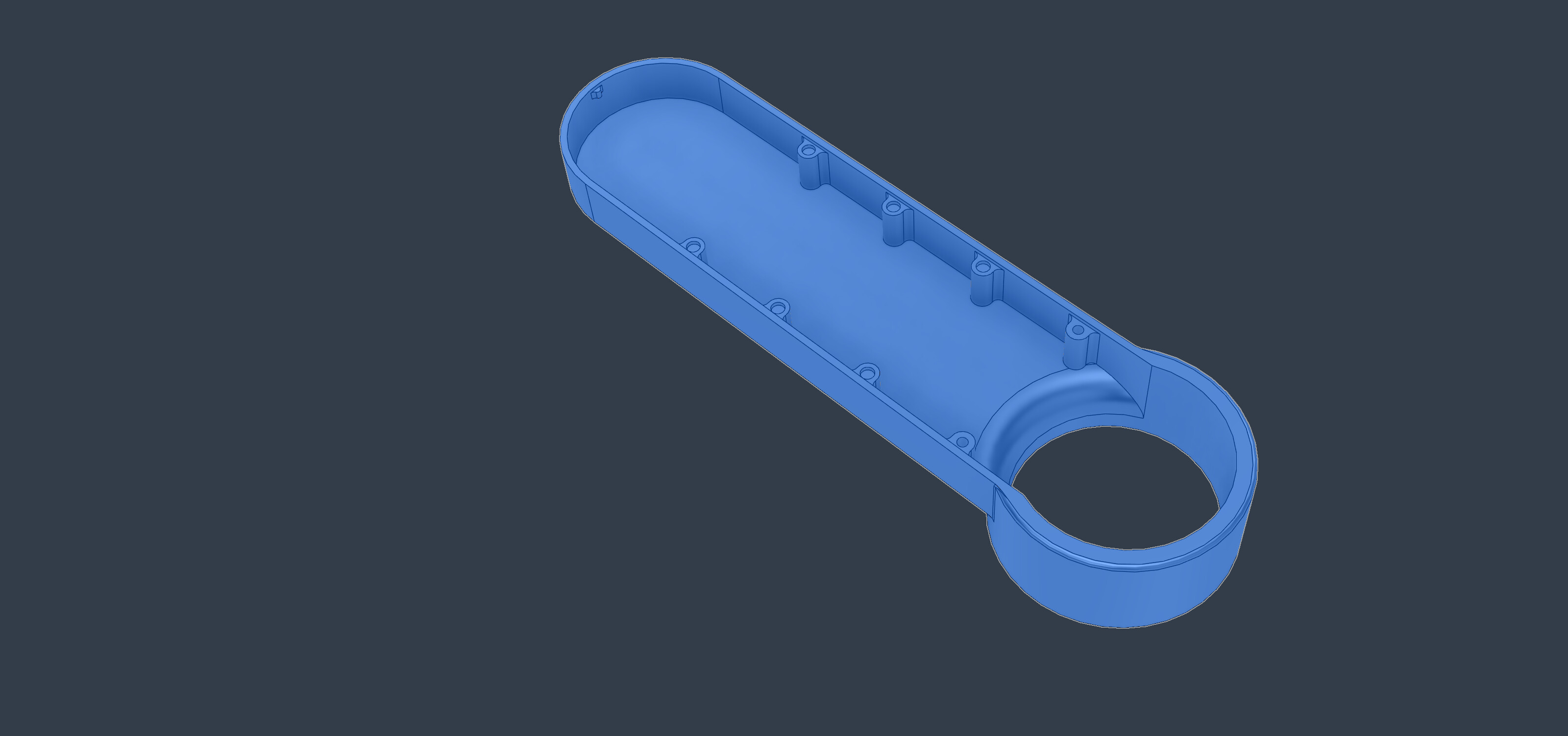
PassThruBottomFillet.stl (238.9 KB)
1 Like
did you consider PWNCNC dust boot V9? They do not sell the item any more, but the 3d-files.
Their bracketing system is available here:
I still could get the items produced, they are Z-independent, and since I often use thick stock I am more happy with Z-independent dust shoes.
With these items one needs a “collar” where the spindle passes through, I made one like this:
1 Like