I am trying to make a top for a box and I would like to have the edges either rounded over or the same effect as on Ogee router bit on the edges.
What bits can I used to accomplish this and how would I go about setting it up in Carbide Create ?
I am trying to make a top for a box and I would like to have the edges either rounded over or the same effect as on Ogee router bit on the edges.
What bits can I used to accomplish this and how would I go about setting it up in Carbide Create ?
You could model it completely in 3D using Carbide Create Pro.
Or, see:
If I model it in Carbide Create Pro what bit would I need to cut it ?
3D toolpaths are usually done with a series of Ball-noses tools — if you want a specific angle such as the 90 degree of a typical ogee then you would want to use a square tool for that as well.
Will the software prompt for the proper tool or do I have to figure that out ?
You will need to choose/set the tooling.
For more on 3D toolpaths see:
https://carbide3d.com/hub/courses/create-pro/3d-toolpaths/
You’ll probably want to try both techniques and compare time estimates, and do some test cuts to determine which has a better result (my money will be on the specialized tool as described at the prescribed link).
I have CC pro now and I don’t understand how to make a round over with it at all. Can you tell me how I would accomplish this ?
Offset geometry by twice the radius, model as a rounded form.
Offset geometry by the radius, model as an equal flat height to get a flat region which ends up being rounded.
If you’ll upload the file you are having trouble with we can walk through that with you.
I have no idea what you are saying. I have very little experience with my Shapeoko.
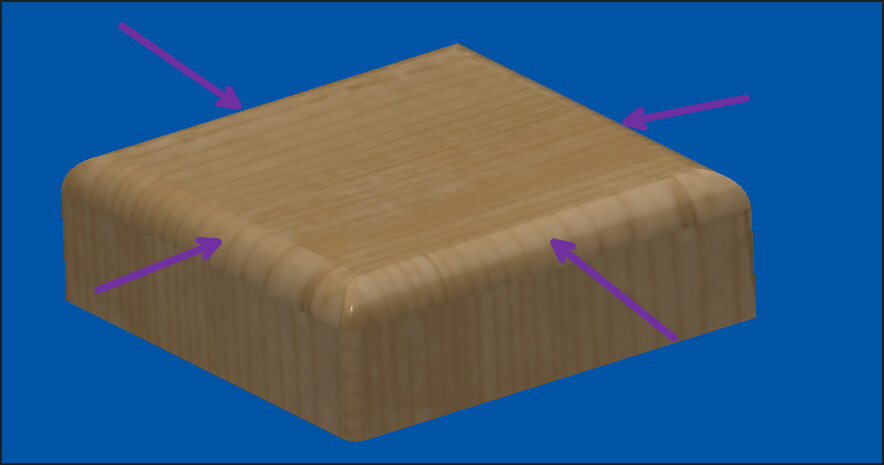
I am trying to make a top to a box. Dimensions are 6" x 4 on a 3/4" piece of oak" I want to have the edge rounded over. and I plan on dishing out the top 4" x 3" 1/8 to 1/4" deep
Another option is to set the stock height or you Z setting artificially high so the bit will not contact the stock surface. Run your toolpath like an “air cut” and see how the machine will carry out the cut. This allows you to change the toolpath as needed to get the desired cut. I used this method (and still do when trying something new) on my Pro 5 4x4. I run a toolpath, make an adjustment and run another air cut. This allowed me to learn and understand the relationship of the CAD/CAM interface.
I honestly could have spent $120 on a cordless router and bits and already had the job done.
I don’t understand why there is not simple options in the software to mimic real world common uses like a prebuilt library of edges that can be applied to the project such as round over, ogee etc.
Likewise there are no tutorials to accomplish this that I can find on the carbide site
The 3D options in CC pro seem very limited and limiting compared to Vectric
I appreciate that but unfortunately I am under a time constraint at the moment.
Given the image:
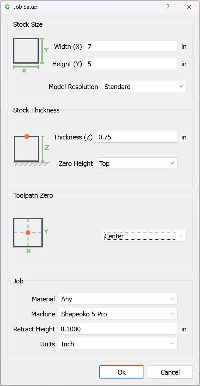
and
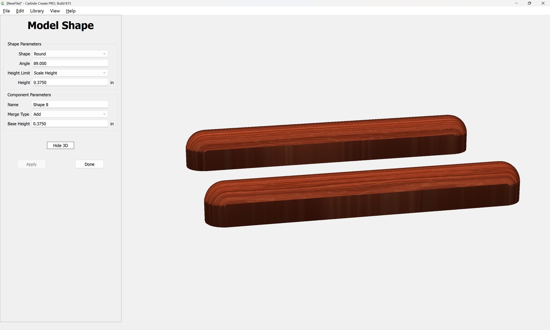
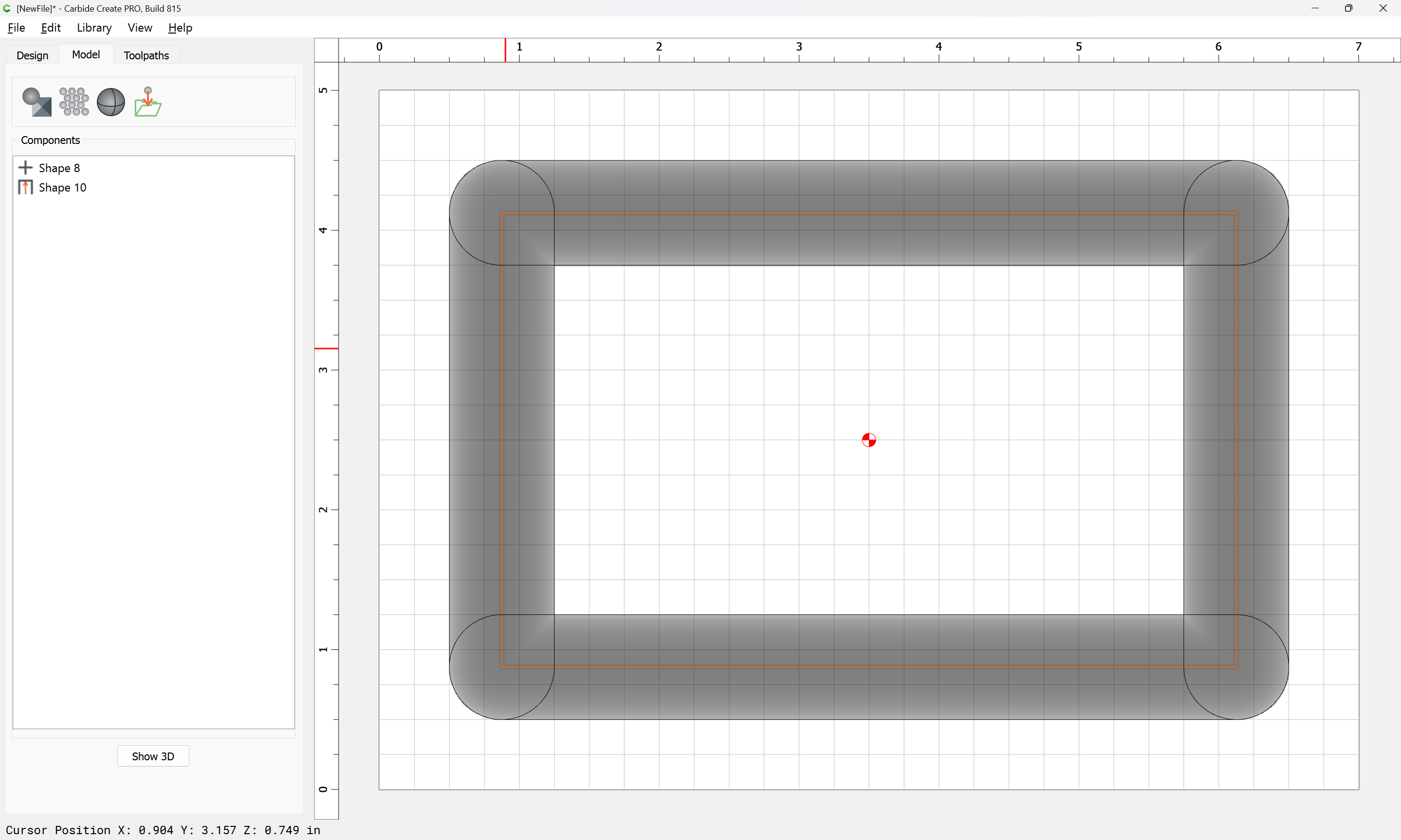
we launch Carbide Create Pro and set up the job:
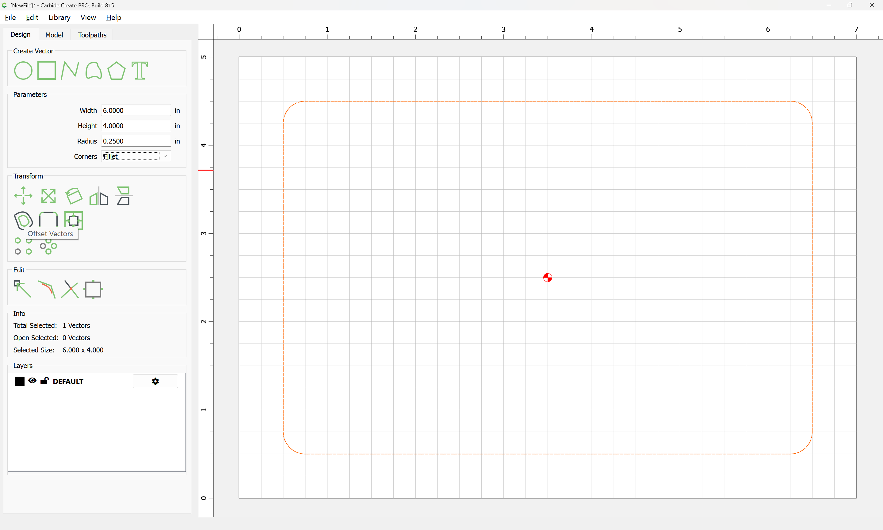
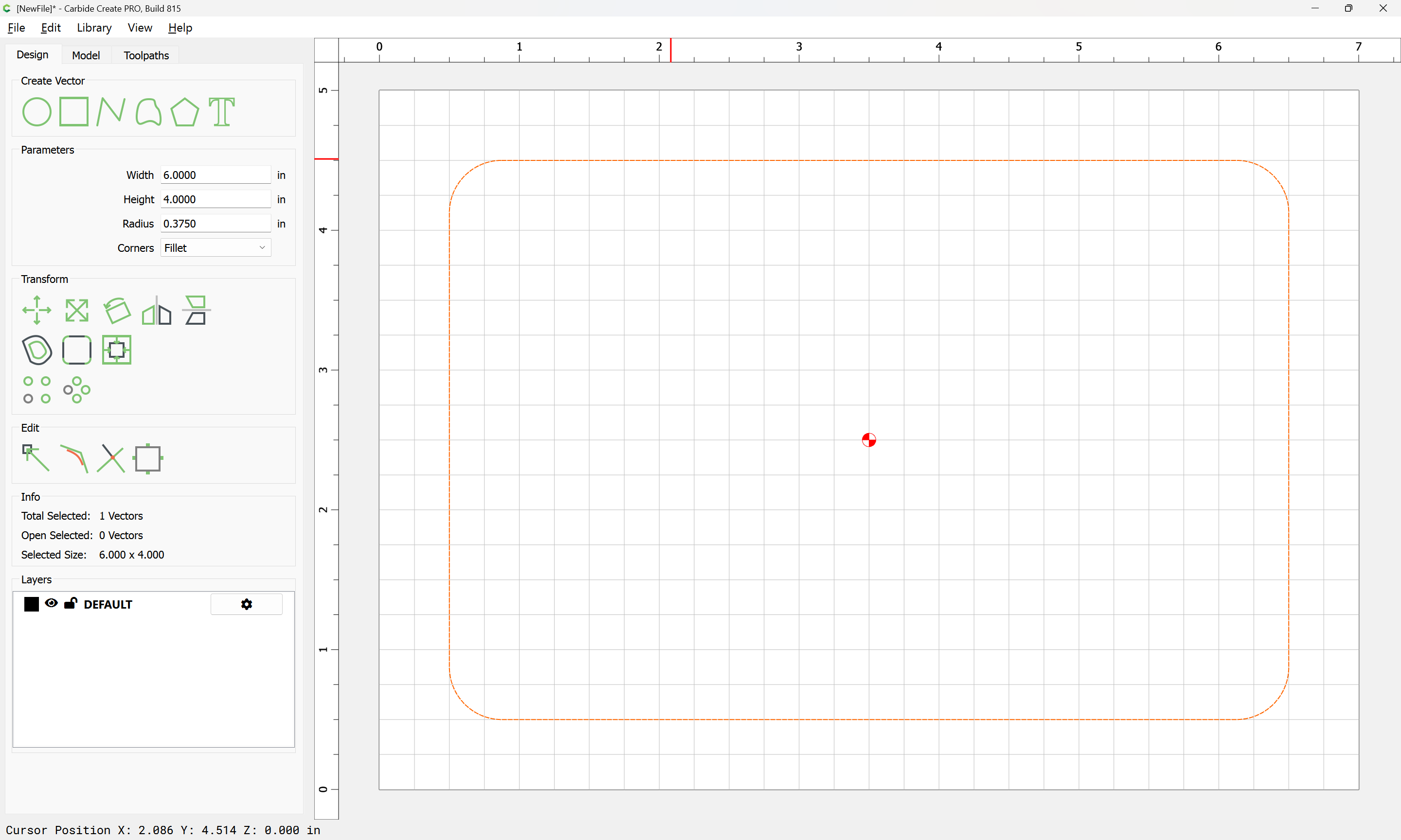
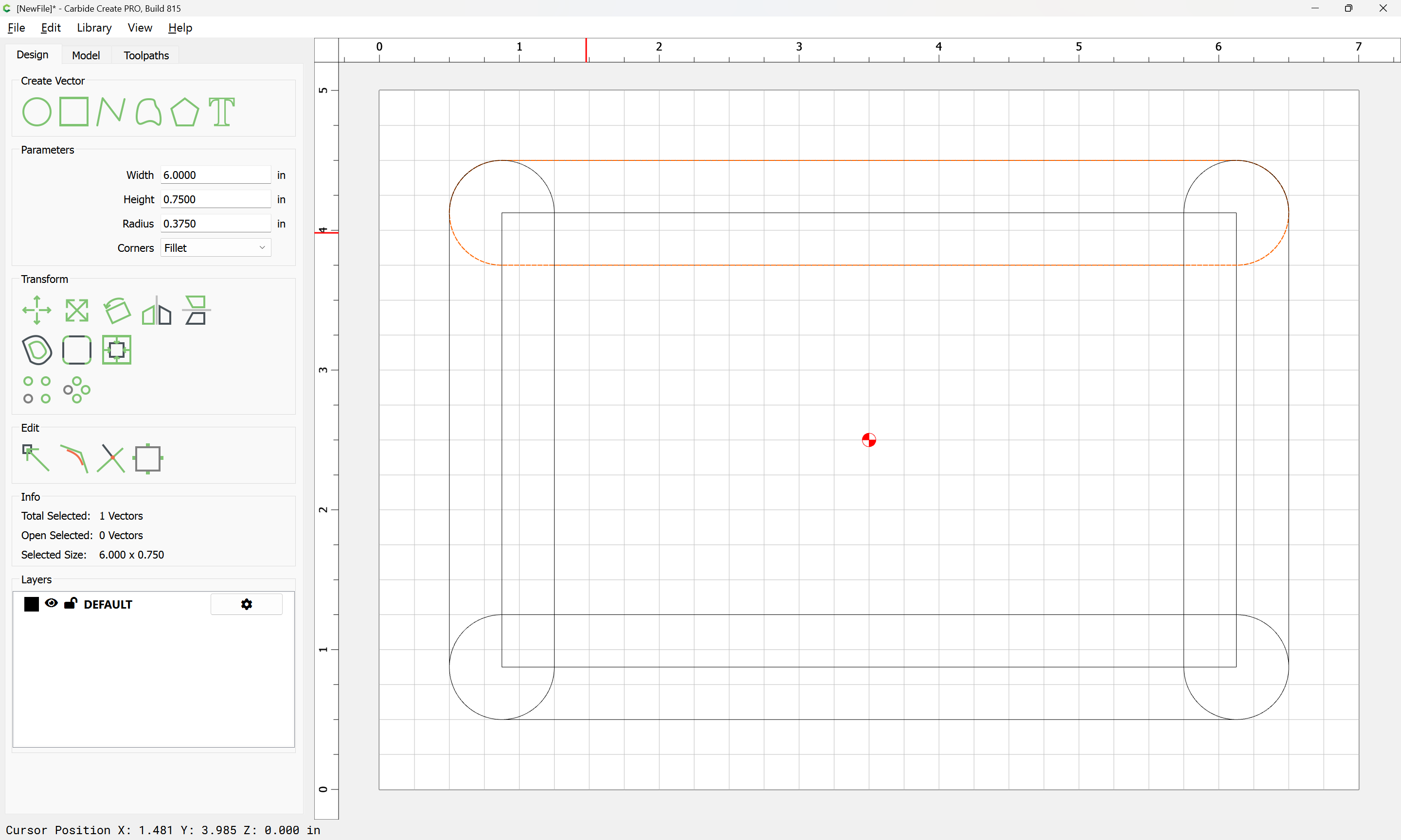
Draw a rectangle for the part:
and set the corners to match the rounding:
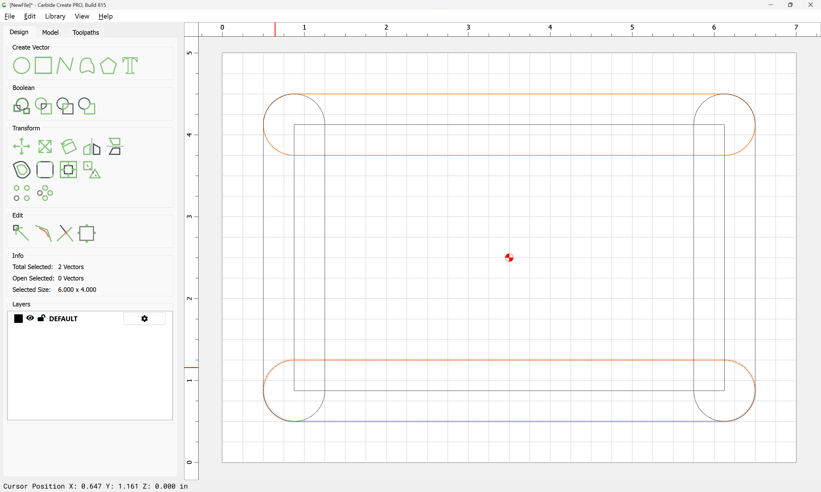
Note that because this design has essentially joined elements, it will be necessary to model in pieces:
Apply
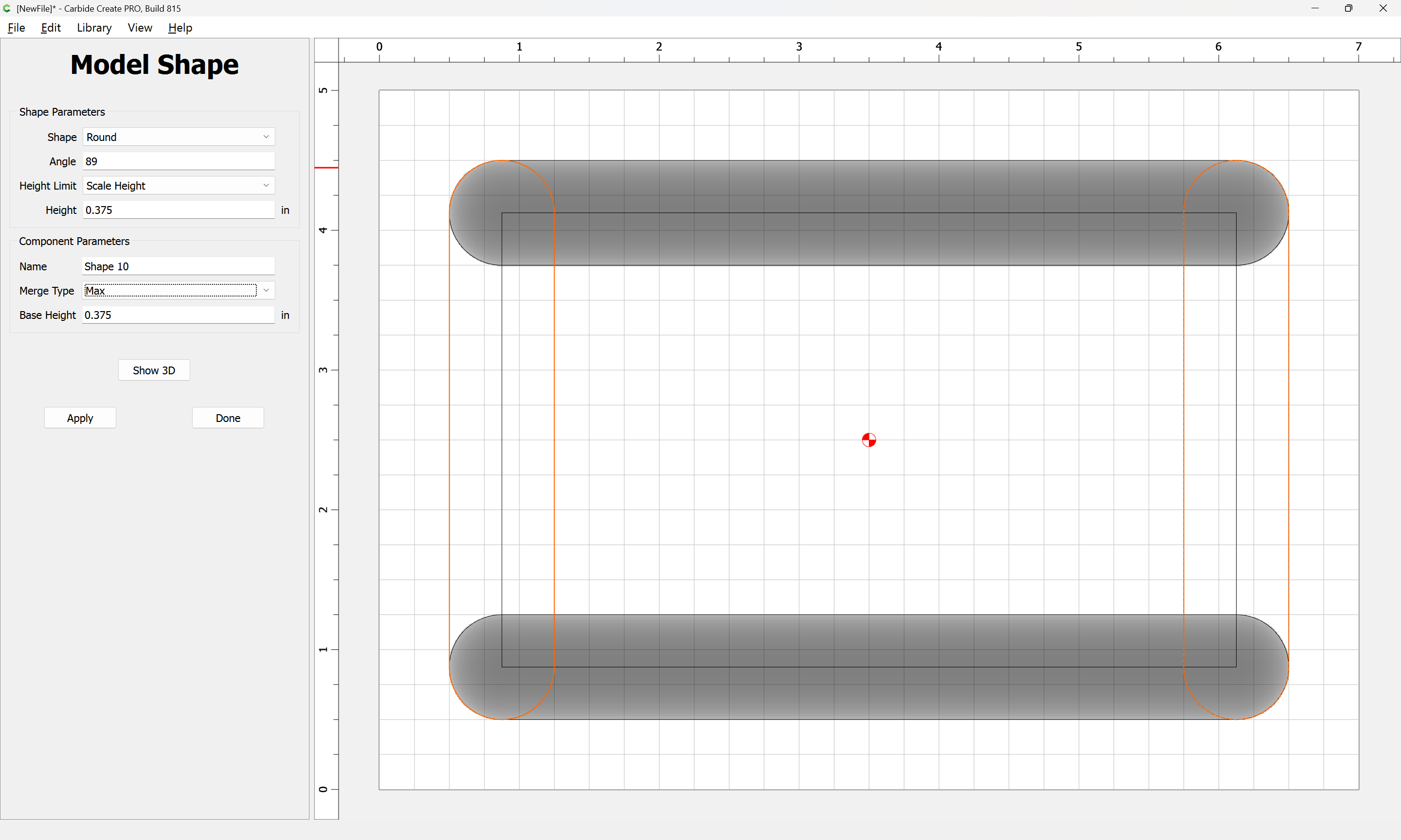
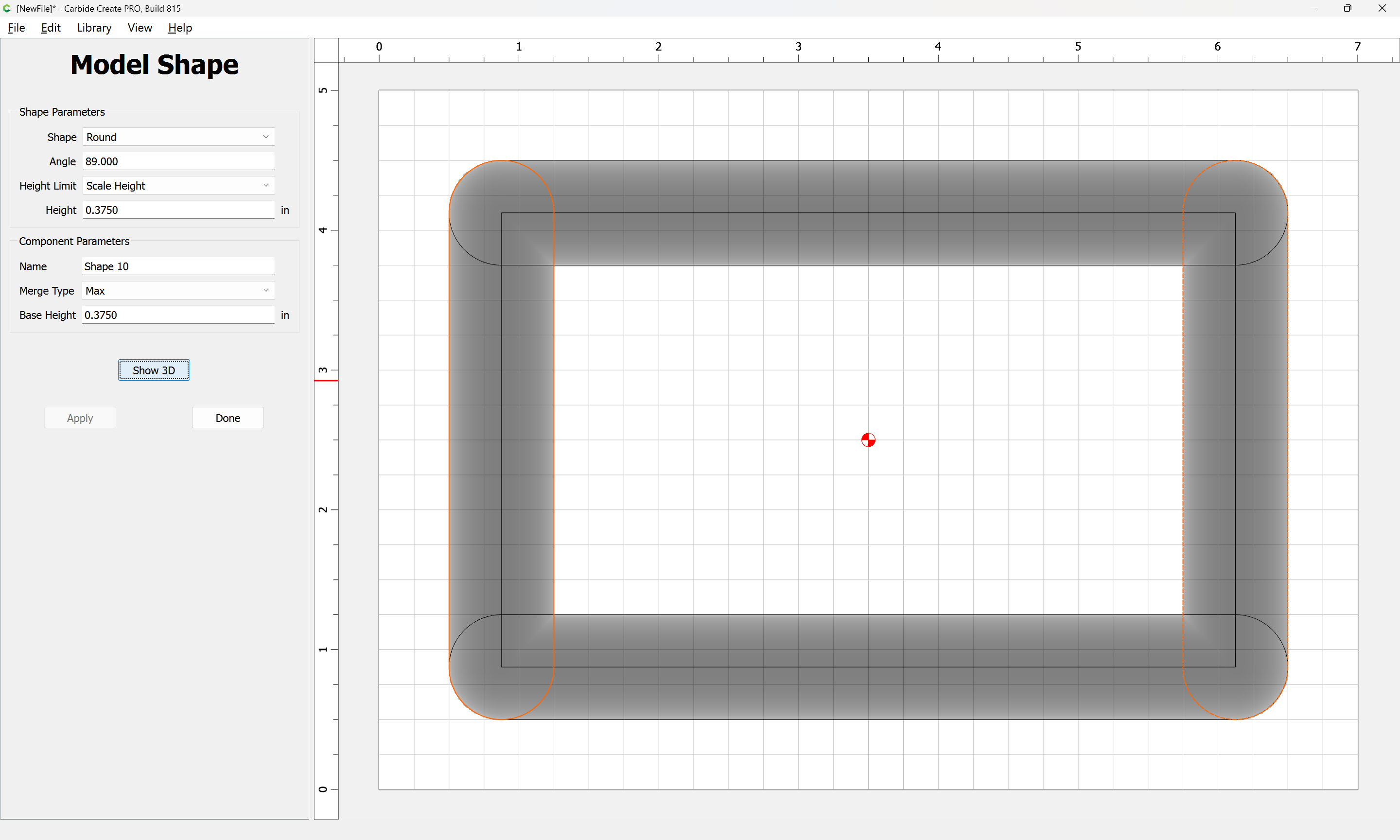
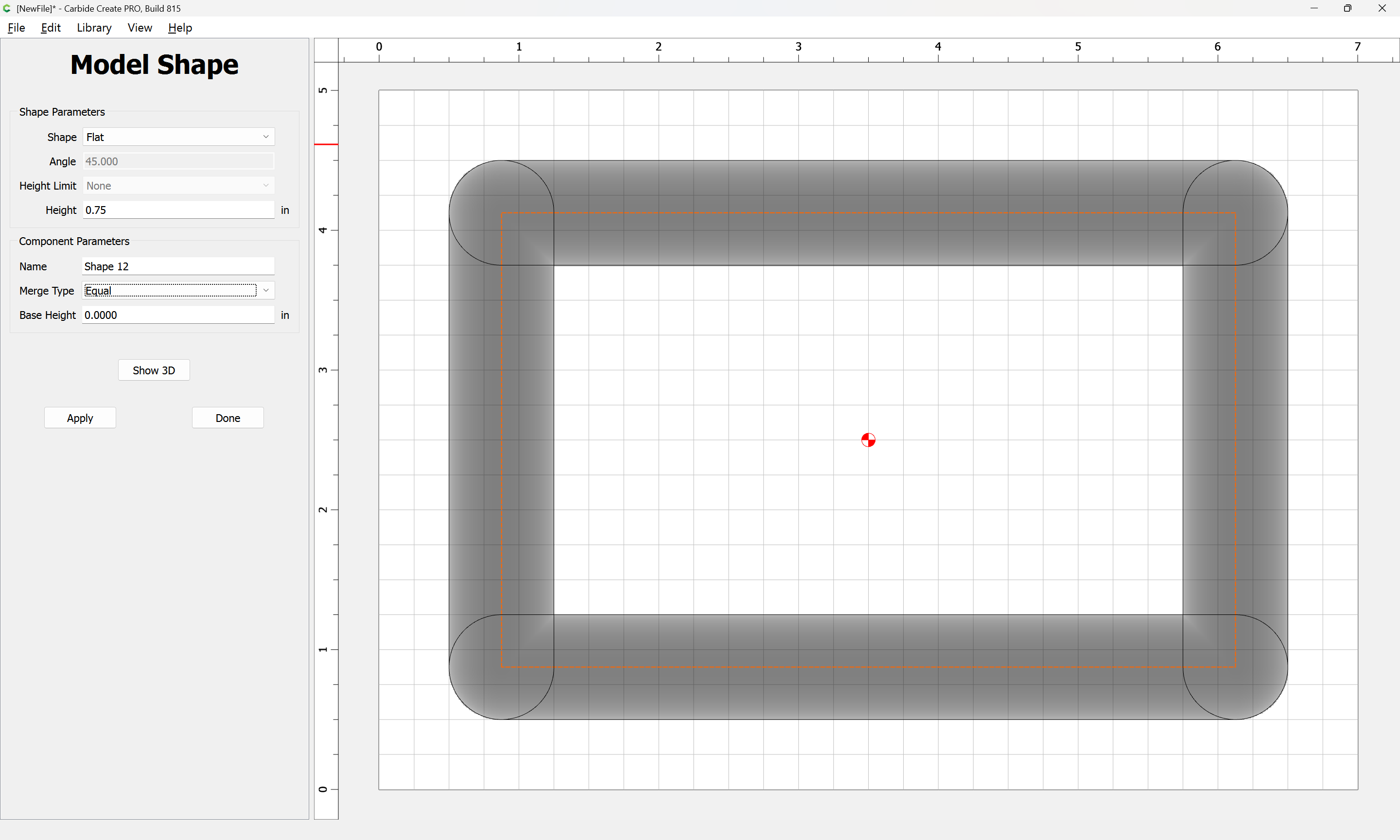
Repeat for the sides:
changing the Merge type to “Max”:
Apply
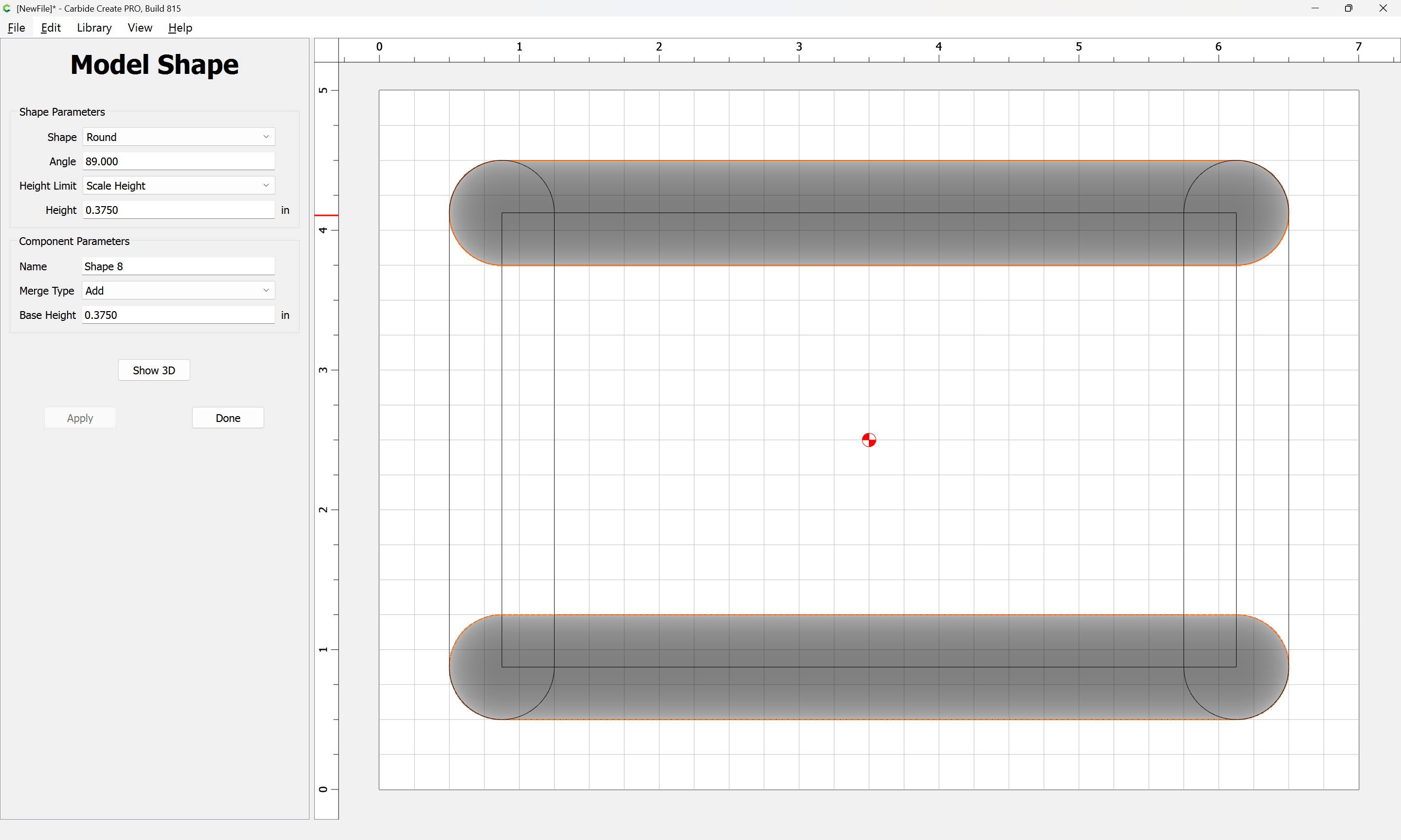
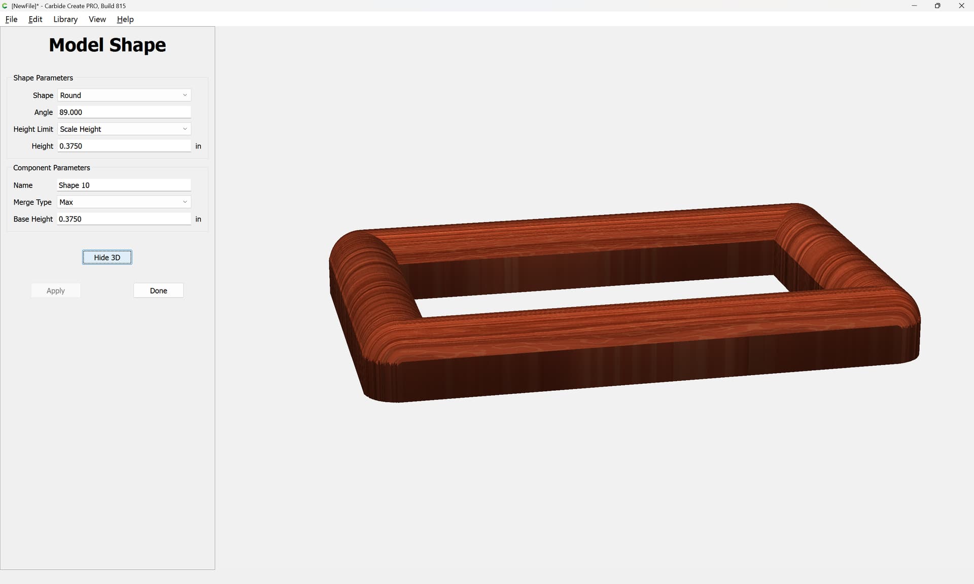
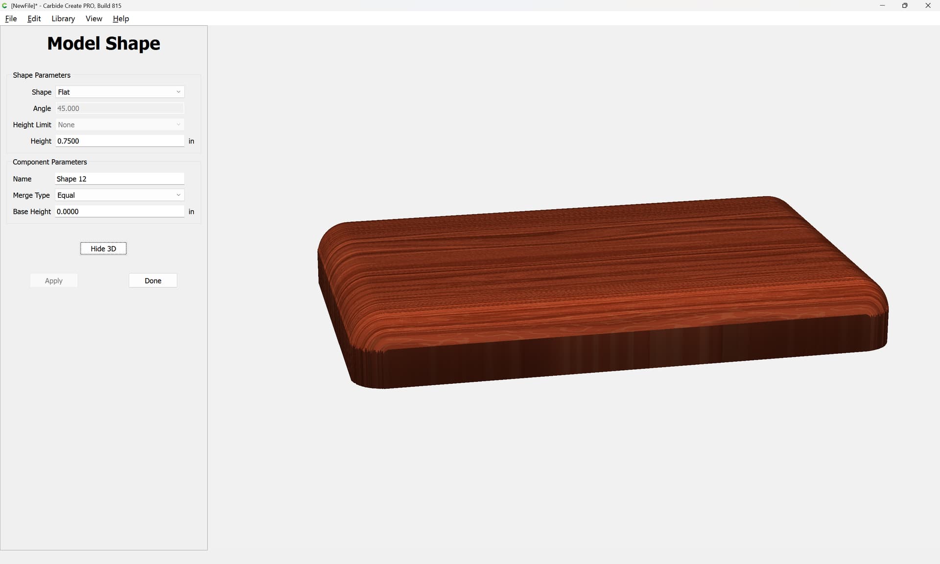
Show 3D:
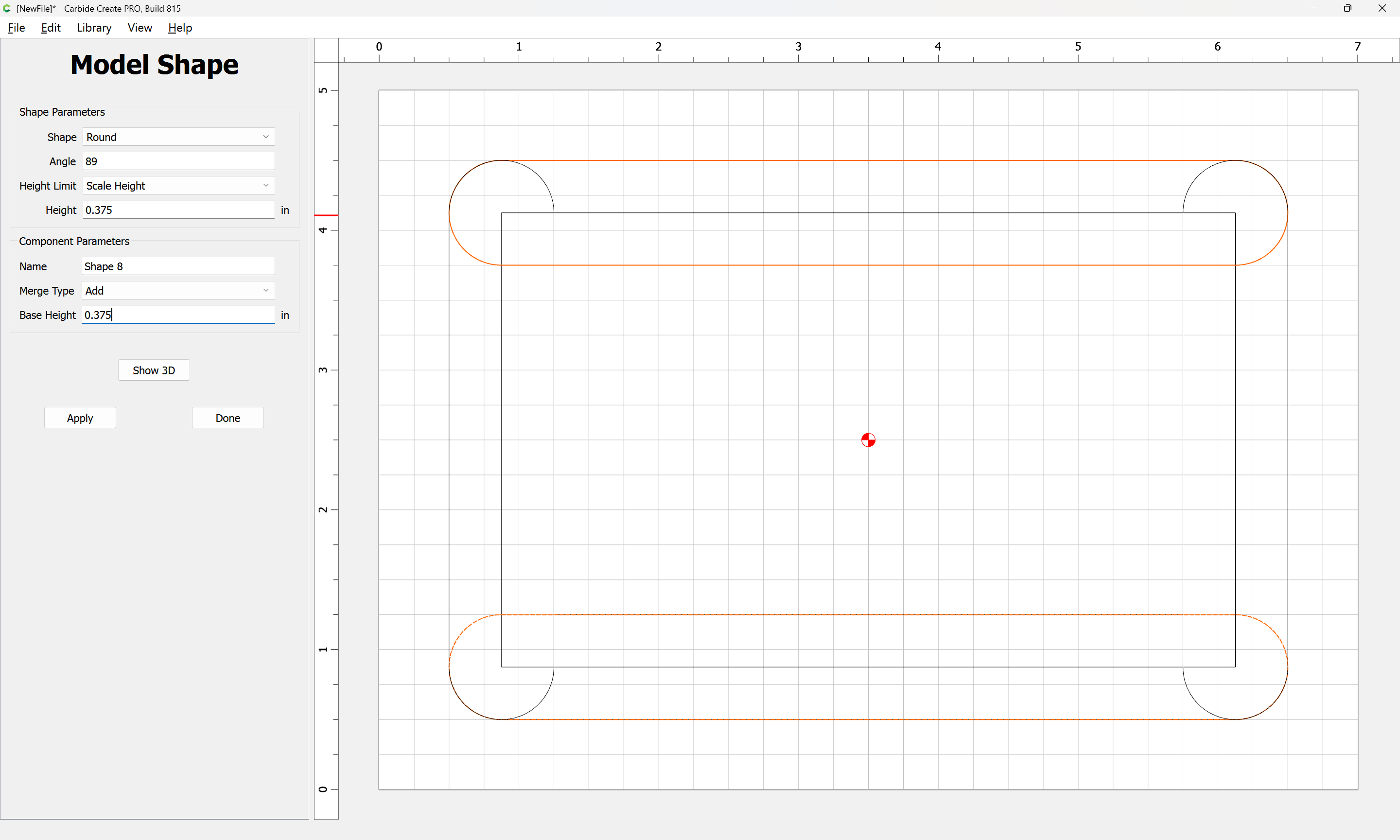
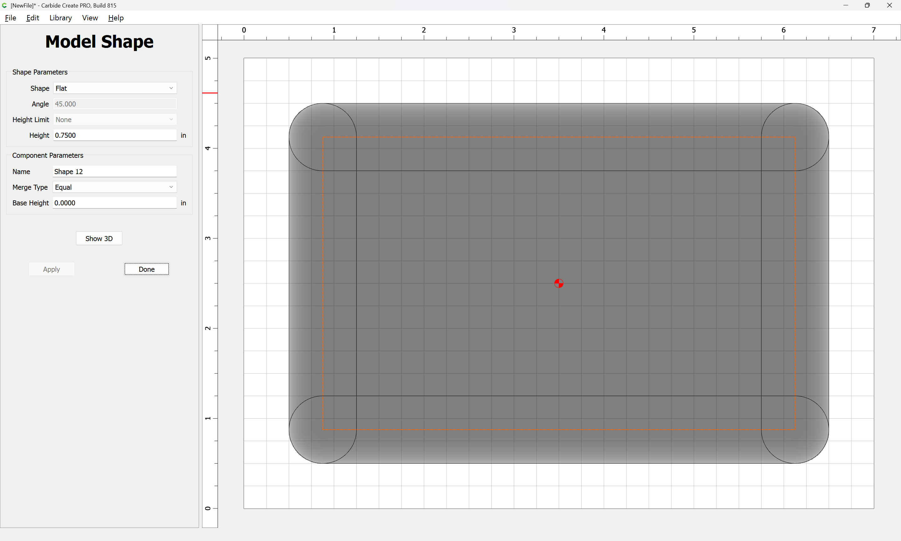
Select the first inset:
and model it as Equal to the desired height:
Apply
Show 3D:
wow, thank you this is close to what I am looking for. Two questions
how would I make the rounding so it extended to the bottom (I basically want to make it look like quarter round.
how do I apply the rounding but have the corners be square so that each corner comes to a point like as if you mitered 3/4" quarter round moulding together at each corner. The reason for this is the box will be square. so this way the lid matches the box.
Ok, if you use a 1/2” round over, set the offset outside-right of the tool path. Set the bottom of the arc of the cutter edge at the stock Then set max depth for 1/4” depth. Practice this on a scrap piece of stock and dial it in. This is the same process I do when cutting round overs to dial them in.
When I use this process, which is rare not eh cnc. It’s much easier to just use the router table of trim router to do this task.
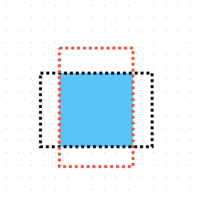
To make the corners “square” as you mention above you will need to start the toolpath before the side you rounding over and have the toolpath go past the corner. In essence draw two more toolpaths, basically making a rectangle of the top and bottom of the square, then make another rectangle for the right and left sides of the square. This way the roundover does not change path on the exact corner (90 deg) resulting in a complete roundover of the 90”s.
If you want the roundover from the top to the bottom (one continuous curve) of the stock you have to have a roundover for the dimension of your top “OR” you have to machine the stock to match the roundover profile.
The square is your stock, 2 toolpaths. However, depending on the type/grain of wood you use you might get tear out. Which is why I usually do this with a trim router and use a climb cut on the corners or waste board to prevent tear out or chip out.
One rectangle black and one red to illustrate my ramblings above.
I followed along but changed the modeling, I set the height for .75 and the angle for 75 in the center it should be a pocket that is .25" deep but I may need to change this to .125" deep. I have attached the file. Not sure this is going to run right or how to setup the tool paths
Box Lid.c2d (160 KB)